Electric Mirror Aria User manual

Lighted Mirrors
Installation Guide ELECTRIC MIRROR®
Installation Guide ELECTRIC MIRROR®
ELECTRIC MIRROR® 425.776.4946 | electricmirror.com |sales@electricmirror.com | © 2019 Electric Mirror. All rights reserved. | 2.0419.MC
1
CONGRATULATIONS
You’ve purchased the finest lighted mirror available, from the global leader in mirror technology. This lighted mirror is
quick and easy to install, and is designed and manufactured to offer you years of enjoyment.
Please read these instructions thoroughly before beginning installation. If you have any questions, please contact our
Customer Service team at 425.776.4946, or customer.support@electricmirror.com.
APPLICATION
These installation instructions apply to the lighted
mirrors listed below with a Part # prefix that includes
the number 2. For example, the Celebration lighted
mirror Part # prefix is CEB2.
To confirm the Part # for your product, look for the
product sticker on the inside of the chassis.
•Aria (ARI2)
•Bela (BEL2)
•Crown (CRO2)
•Eternity (ETE2)
•Eyla (EYL2)
•Facet (FAC2)
•Fusion (FUS2)
•Integrity (INT2)
•Jewel (JWL2)
•Momentum (MOM2)
•Novo (NOV2)
•Novo 4 (NOV42)
•Prism (PRI2)
•Reflection (REF2)
•Serenity (SER2)
•Silhouette (SIL2)
•Trinity (TRI2)
For mirrors not listed above, see additional Installation Instructions located at
www.electricmirror.com/installation-instructions.
TABLE OF CONTENTS
1. Review important safety instructions..................................................................................................................................................2
2. Unpack your lighted mirror...................................................................................................................................................................... 2
3. Determine the mirror location ................................................................................................................................................................3
4. Prepare the electrical .................................................................................................................................................................................4
5. Mount the chassis......................................................................................................................................................................................... 5
6. Connect the electrical ................................................................................................................................................................................6
7. Connect optional upgrade technology...............................................................................................................................................7
8. Wire the dimming switch..........................................................................................................................................................................8
9. Hang the mirror........................................................................................................................................................................................... 10
10. Clean the mirror ..........................................................................................................................................................................................12
Lighted Mirrors
Installation Guide ELECTRIC MIRROR®
Installation Guide ELECTRIC MIRROR®
ELECTRIC MIRROR® 425.776.4946 | electricmirror.com |sales@electricmirror.com | © 2019 Electric Mirror. All rights reserved. | 2.0419.MC
2
1. REVIEW IMPORTANT SAFETY INSTRUCTIONS
A. Use a qualified electrician.
Your lighted mirror must be installed by a qualified technician or electrician. These instructions assume an
electrical connection has already been brought to the mirror location in the wall. All electrical components must
be serviced by qualified electricians. Power source must be disconnected prior to servicing components.
B. Read and follow instructions.
For proper installation, read and install the mirror according to these instructions, and keep a copy for future
use. Failure to follow these instructions voids the warranty.
C. Follow safety precautions.
To prevent injury, the mirror must be installed according to these instructions. Failure to do so could result in
serious injury or death.
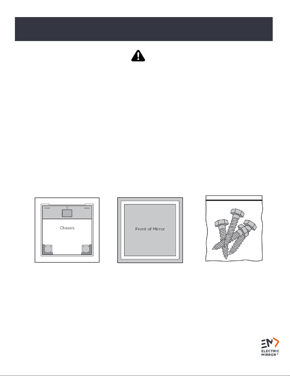
2. UNPACK YOUR LIGHTED MIRROR
A. Verify the contents.
Unpack the boxes, and identify and verify all contents prior to installation. In general, your mirror will include the
following:
Chassis Assembly Mirror Assembly* Mounting screws (4-pack)
*Mirror glass is fragile. Keep edge protectors in place and rest mirror on a cushioned surface. Do not place on a
hard surface.
Lighted Mirrors
Installation Guide ELECTRIC MIRROR®
Installation Guide ELECTRIC MIRROR®
ELECTRIC MIRROR® 425.776.4946 | electricmirror.com |sales@electricmirror.com | © 2019 Electric Mirror. All rights reserved. | 2.0419.MC
3
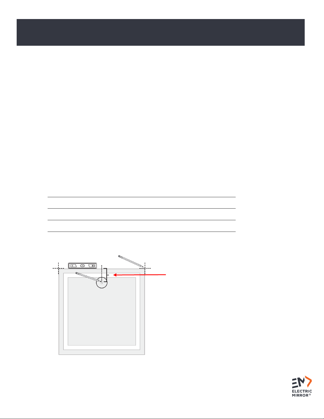
3. DETERMINE THE MIRROR LOCATION
A. Confirm proper mirror orientation.
All lighted mirrors must be mounted in the width x height orientation identified in the part number because the
mirror hanger is permanently attached to the back of the mirror and can only be installed in the designated
orientation. A leveling keyhole is located at the top center of the chassis to aid in identifying the proper
orientation.
B. Determine and mark mirror location on the wall.
The top edge of the mirror glass must be a minimum of 1” from the ceiling.
To ease installation, a keyhole slot is provided in the top center of the chassis. This allows the chassis to
temporarily hang on a single screw while being adjusted.
To identify the proper location for the leveling screw, find the appropriate distance in the chart below for your
specific mirror. Measure and mark that distance on the wall. This mark must be in the horizontal center of the
mirror location. This is the minimum distance needed from the ceiling to the top of the mirror glass.
Mirror Type
Mirror Width
Keyhole Distance from Mirror
Top *
Novo
< 36”
1.75”
Novo
≥ 36”
2.5”
All other mirrors
< 36”
4.75
All other mirrors
≥ 36”
5.5”
*This is in addition to the 1” minimum glass clearance
from the ceiling.

Lighted Mirrors
Installation Guide ELECTRIC MIRROR®
Installation Guide ELECTRIC MIRROR®
ELECTRIC MIRROR® 425.776.4946 | electricmirror.com |sales@electricmirror.com | © 2019 Electric Mirror. All rights reserved. | 2.0419.MC
4
4. PREPARE THE ELECTRICAL
A. Follow safety precautions.
Turn power off to the circuit via the breaker box powering this mirror. Follow all NEC (National Electric Code)
wiring standards for installation.
B. Determine the location where the electrical wiring should come through the wall.
The electrical entry location is the center point from left to right of the mirror chassis. Generally, the wiring
needs to come out of the wall roughly 14 inches from where the top of the mirror glass will be located. For
specific information visit www.electricmirror.com/product-specifications.
C. Bring electrical power to the mirror location.
The lighted mirror requires a switched 120V 60Hz circuit. If your mirror has additional options, there may be
additional power requirements. When bringing out the wiring, leave a 3-foot whip*.
*Ensure a 3’ long electrical whip is available coming out of the wall.
Lighted Mirrors
Installation Guide ELECTRIC MIRROR®
Installation Guide ELECTRIC MIRROR®
ELECTRIC MIRROR® 425.776.4946 | electricmirror.com |sales@electricmirror.com | © 2019 Electric Mirror. All rights reserved. | 2.0419.MC
5
5. MOUNT THE CHASSIS
A. Install the mounting screws.
i. Insert a screw in the mark made earlier, leaving the screw head protruding 1/8” from the wall.
ii. Carefully raise the chassis, align the keyhole with the leveling screw, and hang the chassis on the wall.
iii. Ensure the chassis is level.
iv. Insert mounting screws in the top two corners. Multiple screw locations are offered; insert a minimum of
one screw per corner. These mounting screws are load-bearing and should be drilled into a wall stud or
suitable backing (if this isn’t possible, use appropriate wall anchors).
v. Remove the keyhole screw, it will be used as a mounting screw for one of the bottom corners.
vi. Install the bottom mounting screws. The chassis mounting is now complete.
Insert the leveling screw first.
Next, insert screws in the top corners.
Finally, insert screws in the bottom corners.
This manual suits for next models
16
Table of contents
Popular Home Lighting manuals by other brands


JONATHAN Y
JONATHAN Y JYL6007A quick start guide

Philips
Philips Ledino 31606/11/16 Specifications

Safavieh Lighting
Safavieh Lighting CANDRI TBL4427A manual

Hunter
Hunter Bullet Spotlight Kit Owner's guide and installation manual

Philips
Philips 405441213 user manual

Philips
Philips Halogen Light Brochure & specs


