Electrolux Professional Jetsave User manual

Installation manual
Jetsave Dosing System
For washer extractors L6000 with Clarus Vibe
Original instructions
438917541/EN
2022.10.04


Contents
Contents
1 General safety information ...................................................................................................................5
2 Symbols .............................................................................................................................................6
3 Introduction.........................................................................................................................................7
4 Recycling instruction for packaging.......................................................................................................8
5 Installation ..........................................................................................................................................9
5.1 Installation of the Jetsave system................................................................................................9
5.2 Electrical connection ................................................................................................................15
5.3 Selection of system/pumps.......................................................................................................18
5.4 Pairing the pumps / Addressing the I/O board.............................................................................18
5.5 Priming the pumps ...................................................................................................................20
5.6 Calibrating the pumps ..............................................................................................................20
5.7 Installation of low level probe (option) ........................................................................................21
5.8 Connection with low level sensors/probes..................................................................................21
6 Technical specification.......................................................................................................................23
7 Trouble shooting and service..............................................................................................................23
8 Disposal information..........................................................................................................................24
8.1 Disposal of appliance at end of life ............................................................................................24
8.2 Disposal of packing..................................................................................................................24
The manufacturer reserves the right to make changes to design and component specifications.


Installation manual 5
1 General safety information
These installation, operation and servicing instructions shall only be performed by qualified personnel.
The Jetsave system must be installed in accordance with all applicable electrical and plumbing standards. All washer
extractor and dispenser power must be isolated during installation and/or any time the dispenser is maintained or
serviced.
•Always verify all voltage sources with a meter.
•Do not locate the pump-stand under plumbing fittings that could leak.
•Ensure that the installer has enough room to carry and lift the units when installing the
Jetsave system.
•Do not pick up unit by supply cord.
•Wear PPE (Personal Protective Equipment) when dispensing chemicals or other mate-
rials or when working in the vicinity of all chemicals, filling, or emptying equipment.
•Always observe safety and handling instructions of the chemical manufacturers.
•You must follow all precautions as advised on the product safety data sheet.
•Always direct discharge away from you or other persons or into approved containers.
•Always dispense cleaners and chemicals in accordance with manufacturer's
instructions.
•Always exercise caution when maintaining your equipment.
•Always re-assemble equipment according to instruction procedures. Be sure all compo-
nents are firmly screwed or latched into position.
•Keep equipment clean to maintain proper operation.
•NOTE! This appliance is not be used by persons (including children) with re-
duced physical, sensory or mental capabilities, or lack of experience and knowl-
edge, unless they have been given supervision or instruction.
•This appliance can be used by children aged from 8 years and above and persons with
reduced physical, sensory or mental capabilities or lack of experience and knowledge if
they have been given supervision or instruction concerning use of the appliance in a
safe way and understand the hazards involved.
•Children shall not play with the appliance.
•Cleaning and user maintenance shall not be made by children without supervision.
•NOTE! Appliances connected to the water mains by detachable hose should use
hoses provided with the appliance and should not reuse previous.
•NOTE! If the supply cord is damaged, it must be replaced by the manufacturer, its
service agent or similarly qualified person, in order to avoid a hazard.
•NOTE! A locally approved back-flow prevention device must be installed with the
appliance for safe and legal operation. An approved back-flow prevention is pro-
vided: 432930084 DOUBLE CHECK VALVE.
•NOTE! The Jetsave operates on 24V~ / 0.1A and must only be supplied at Safety
Extra Low Voltage (SELV).
•NOTE! This appliance must only be supplied at safety extra low voltage corre-
sponding to the markings on the appliance.
•NOTE! It is a legal requirement, if the unit is supplied from the water mains, that a
backflow device is installed offering protection equal or higher than the chemical
class being used. This is to prevent back siphoning of non-potable substances
into the water mains.

6Installation manual
2 Symbols
Warning/Caution
An appropriate safety instruction should be followed or caution to a potential hazard exists.
Dangerous voltage
To indicate a hazardous arising from dangerous voltages.
Protective earth (ground)
To identify any terminal which is intended for connection to an external conductor for protection against electric shock
in case of a fault, or the terminal of a protective earth (ground) electrode.
Refer to product manual
Read the instructions before using the machine.
Protective Personal Equipment
The use of appropriate eyewear shall be used.
Protective Personal Equipment
The use of appropriate safety gloves shall be used.
Protective Personal Equipment
The use of appropriate protective clothing shall be used.

Installation manual 7
3 Introduction
The Jetsave system is designed to be connected directly to the washer extractor using two multi pin connectors.
The Jetsave controls the amount of product dispensed and product delays if required.
The Jetsave system connected and supplied from the washer extractor 230V, 50/60Hz 0.1A (Max).
The Jetsave is an integrated water flush chemical dispensing system.
Power Data
fig.X01323A
• The washer extractor is provided with AMP Style power and interface connectors so no external power source is
needed for the pumps.
• The Jetsave system is for indoor use only.
• Ensure that the unit can be mounted in an accessible position above the height of the required discharge location.
Note!
Above shoulder height would require steps or platform.
• The Jetsave control unit can be installed within 3 m from the washer extractor (with possibility to extend the dis-
tance up to 15 m using optional power and the data cable) and close to product containers and at a convenient
height for servicing, about 1–1.5 m.
• The input tubing from the chemical container to the Jetsave shall not be more than 2 m.
• The tubes must not be twisted and shall hang freely without any sharp bends. Longer tubes requires maintenance
more often.
• The Jetsave 2-5 pumps can be daisy chained to create up to 15 pumps with 3 Jetsave units. (6-10 pumps can not
be daisy chained).
• Max. 3 pumps can be ordered from the washer extractor and each pump will be run in the queue.
Jetsave PNC’s Description
988930001 Complete kit with 2 pumps, 550 ml/min
988930002 Complete kit with 3 pumps, 550 ml/min
988930003 Complete kit with 4 pumps, 550 ml/min
988930004 Complete kit with 5 pumps, 550 ml/min
988930005 Complete kit with 6 pumps, 550 ml/min
988930006 Complete kit with 8 pumps, 550 ml/min
988930007 Complete kit with 10 pumps, 550 ml/min

8Installation manual
4 Recycling instruction for packaging
1
1
1
2
3
3
4
2
fig.X02421
Fig. Description Code Type
1 Plastic bag LDPE 4 Plastics
2 Cable Ties Other Plastics (Nylon)
3 Cling film LDPE 4 Plastics
4 Cardboard packaging PAP 20 Corrugated card board

Installation manual 9
5 Installation
5.1 Installation of the Jetsave system
The wall where the Jetsave is to be mounted must support wall anchors and must be flat and perpendicular to the
floor.
Use the wall mounting brackets as a templates and mark the location of the holes on the wall.
Drill the holes and put in suitable wall anchors. Fasten the wall mounting bracket with the screws. Make sure the wall
mounting brackets are in level.
Mount the electrical box on the wall bracket and secure with the clips.
There are different sizes of the Jetsave system; unit for 2, 3, 4, 5, 6, 8 and 10 pumps.
Product 2-6 pumps Product 8-10 pumps
For 2-6 pumps products, drill the holes for the pump units according to the following figure.
132.4 mm
158.9 mm
fig.X02401
For 8-10 pumps products, drill the holes for the pump units according to the following figure.
339.9 mm
207.5 mm 132.4 mm132.4 mm
158.9 mm
fig.X02358

10 Installation manual
Connections of Jetsave control unit
Product 2-5 pumps Product 6-10 pumps
B
C
E
F
HA
D
G
KJ
E
HA
D
G
A Low level alarm port x 5 (cable glands)
B Data out
C Pairing button
D Data in
E Power in (from washer extractor 230V, 50/60Hz 0.1A Max)
F Power out
G Pump power connection
H Earth connection
J Pairing button No.1 (1st I/O board)
K Pairing button No.2 (2nd I/O board)
Cable glands = Connection of low level sensor inputs (low level alarm ports).
The pairing button on the underside of the Jetsave control unit is used to pair the device to the washing machine.

Installation manual 11
Water connection
Connect the incoming water supply (A) to the Jetsave pumps unit using the fittings provided. This will be a 3/4” Fe-
male BSP swivel. Ensure that the incoming water supply hose is supported so that it does not create unnecessary
force on the inlet.
Caution
The one way valve (C) must be installed. The one way valve is offering protection equal or higher than the chemi-
cal class being used. This is to prevent back piphoning of non-potable substances into the water mains.
Caution
The water inlet pressure must be min. 26 psi/1.8 bar and max. 90 psi/6 bar.
The one way valve (C) must be installed to the main water pipe or at the tap to avoid risk of breaking at inlet (A).
The hose (D) and adapter (E) are not included in the kit. They can be ordered as accessories or any extra required
adapters which are field supplied can be used.
Connect the water outlet (B) to the washer extractor using the hose. Secure the hose to barb with a clamp.
Hose sets used to connect the Jetsave to the mains water supply must also be compliant with IEC61770.
AE
D
C
C
B
alt. 1
alt. 2
D=15 mm
1/2”
1/2”
1/2” 3/4” 3/4”
1/2”
fig.X01354C
Connection of the pickup tubes
Before connection, the Jetsave pumps unit has to be opened. Use the screw driver to open the Jetsave pumps unit.
fig.X02361

12 Installation manual
NOTE!
The check valves (D) are supplied detached in a bag with the unit. To prevent dam-
age, do not install hoses to the check valve while connected to the manifold.
D
FL 1 2 3 4
fig.X02362
Warning
Do not connect any chemical hose to the (FL) flush position.
Cut the hose to the length needed.
Push the hose (E) on to the check valve (D) and secure with a cable tie. Connect the elbow (F) to the manifold and
secure with the white clip (G).
F
G
2
3
D
E
1
fig.X01357

Installation manual 13
Remove and drill a hole in each lid to the chemical containers to be used for the tubes to pass through. The hole shall
be ⌀20 mm (3/4”). Use cable tie to fasten the suction pipe under the lids to prevent the suction pipes of floating or
moving up from the containers.
NOTE!
Do not drill the hole when the lid is fastened to the chemical container.
Fasten each lid to the chemical containers again and insert the inlet tubes in the holes.
fig.X01321B
14 Installation manual
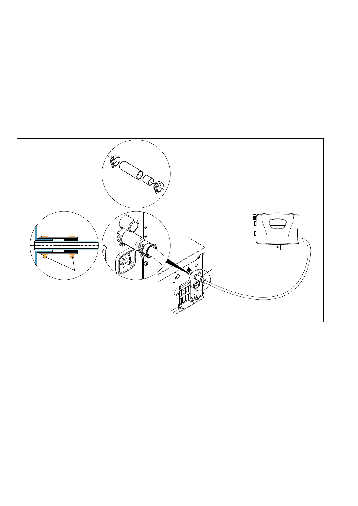
The washer extractor is prepared for connection of external dosing systems or water re-use systems etc.
The connections are closed at delivery.
• Open the connections (A) that shall be used by drilling a ⌀17 mm hole where the hoses shall be connected. Any
extra required adapters which are field supplied can be used.
NOTE!
Make sure there is no burrs left after drilling.
• Connect the hose from the right side of the Jetsave pumps unit to the connection to be used on the washer
extractor.
• Mount the rubber adapter, rubber bushing, clamps, hose from pumps unit to the connection (A) according to the
following figure.
• Tighten clamps (B) with torque 3 Nm (2.2 lbf.ft).
A
B
fig.X02360
If the hoses are made of a soft material such as silicone or similar, make sure the hose size isn't reduced, isn't sharp
bended and is fitted properly to the washer extractor (A). Previous figure isn't valid for the soft hose.
NOTE!
Equipment for external dosing must only be connected to work on pump pressure
and not on network pressure.

Installation manual 15
5.2 Electrical connection
The power supply to the dosing system must never be connected to the machine’s incoming terminal block or to
the edge connectors on the I/O-board.
Isolate the power to the washer extractor.
Disconnect the connector with termination resistor from the machine (B) and connect it to the (B) data out connection
on the Jetsave control unit (1).
B
1
fig.X01168F
Note!
The termination resistor isn't needed for Jetsave 6-10 pumps products.
Save the termination resistor for future use. If the dosing system is uninstalled from the machine, the termination re-
sistor must be remounted on its position on the machine.
Connect the cables from the Jetsave control unit (1) to connections A (power out) and B (data out) on the machine.
Connect the cable from the Jetsave pumps unit (2) to the connection on the Jetsave control unit (1).
B
A
1
2
fig.X01168_4

16 Installation manual
Daisy chain of control units (only applicable for Jetsave 2-5 pumps products)
If two or three Jetsave systems are installed, the connector with termination resistor shall be connected to the last
Jetsave control unit.
If the connector with termination resistor is already connected to an existing Jetsave control unit, the connector with
termination resistor shall be moved from the first Jetsave control unitand connected to the last Jetsave control unit.
fig.X01168_5
Connect the cables from the second Jetsave control unit to the connections on the first Jetsave control unit or if three
Jetsave systems are used, from the third Jetsave control unit to the second Jetsave control unit.
2x
fig.X01168_6

Installation manual 17
It is possible to connect up to 3 Jetsave systems (2-5 pumps) and one ID Interface in a loop.
Note!
The joining kit is needed to combine the pump units against each another. Following the instruction in the
kit.
Examples of possible combinations, 5+2, 5+4. 5+5+2, 5+5+3 etc.
Warning
For continued safety, earth bonding cables should be fitted.
Chemical connections list (Default from factory, Reference from firmware 418810316 Ver. 2.3.0 )
Activated: Pumps/Chemicals
Pump Chemicals name (Output) Each Chemicals name (Output) are changeable to:
Pump 1 Detergent 0: Detergent
Pump 2 Softener 1: Softener
Pump 3 Bleach 2: Bleach
Pump 4 Floor care 3: Floor care
Pump 5 Desinfection 4: Desinfection
Pump 6 W01 - sensitive detergent 5: W1 - sensitive detergent
Pump 7 W02 - delicate detergent 6: W2 - delicate detergent
Pump 8 W03 - sensitive conditioner 7: W3 - sensitive conditioner
Pump 9 Detergent 2 8: Detergent 2
Pump 10 Bleach 2 9: Bleach 2
Pump 11 Floor care 2 10: Floor care 2
Pump 12 Floor care 3 11: Floor care 3
Pump 13 Preservation 12: Preservation
Pump 14 Impregnation 13: Impregnation
Pump 15 Descaling 14: Descaling
Pump 16 Sour 15: Special chemical
16: A02 - colour transfer reducer
17: A03 -leather care
18: Sour
19: Detergent 3
20: Detergent 4
21: Detergent 5
22: Softener 2
23: Softener 3
24: Softener 4
25: Softener 5
26: Booster 1
27: Booster 2
28: Floor care 4
29: Special chemical 2
30: Special chemical 3
31: None
Note!
The washing programs will order or require each chemical from above output, not from pump number. So
chemicals requirement in the wash programs must be matched with Chemicals name (Output). Otherwise,
the machine will wash without any chemical.

18 Installation manual
5.3 Selection of system/pumps
When the Jetsave system has been installed the washer extractor must know which type of system/pumps that are
used in order to function in the correct way.
Proceed as follow:
• Enter the password set by the manager to access the Main menu.
• Activate the Pumps menu.
• Activate the Pumps menu.
A list with different types of systems/pumps will now be visible on the screen.
• Select 1: Venturi for the Jetsave system.
5.4 Pairing the pumps / Addressing the I/O board
• Enter the Advance manager password or Advance service password to access the Main menu.
• Activate the Settings menu.
• Activate the I/O board addressing menu.
Available I/O boards and addresses will now be visible on the screen as a drop down list. The different I/O boards
and addresses are marked with either a green or a grey light.
• Green light = in use.
• Grey light = not in use and available for addressing.
The Jetsave System must be addressed to the 2nd row of I/O Type 22.
• Select the second row for I/O Type 22 (A).
• Press “Add” to start the pairing function.
NOTE!
It is very important to activate the correct address — second row for I/O Type 22. If not, the pumps will not
work.
A
1st
2nd
3rd
fig.X02320

Installation manual 19
When pressing Add, the following message will be displayed indicating that it is OK to paire with the Jetsave system.
fig.X01677
For 2-5 pumps products:
• Press the pairing button (C) on the Jetsave control unit.
For 6-10 pumps products:
• Pairing button No.1 (J) will be for 1st I/O board and Pairing button No.2 (K) will be for 2nd I/O board.
Product 2-5 pumps Product 6-10 pumps
C
KJ
A green light on the second row for I/O Type 22 indicates that the pairing has been successfully done.
fig.X02322

20 Installation manual
If more Jetsave systems shall be used the next one shall be paired to the third row etc.
Up to three Jetsave systems can be used and paired.
5.5 Priming the pumps
• Enter the Advance manager password or Advance service password to access the Main menu.
• Activate the Pumps menu.
• Activate the Priming menu.
• Activate Pump 1 from the list to start priming the first pump.
• Press play to start priming and press stop when ready. (You can also use the pairing button (C) to start and stop,
or button (J) and (K) for 6-10 pumps products).
The hose shall be filled all they way to the outlet of the hose.
Do the same for all the pumps.
5.6 Calibrating the pumps
• Enter the Advance manager password or Advance service password to access the Main menu.
• Activate the Pumps menu.
• Activate the Calibration menu.
• Activate P1 from the list to start calibrating the first pump.
The different steps to be made when calibrating will now be visible on the screen.
1. Fill a container with ml markings (minimum volume 350 ml) with the product to be calibrated and place the tube
from the Jetsave system to be calibrated into the container.
2. Press play to start calibrating.
3. Press stop when 250 ml has been removed from the container.
4. Save the result for the pump.
The first pump has now been calibrated.
Do the same for all the pumps.
Note!
You can also use the pairing button (C) to start and stop the calibration, or button (J) and (K) for 6-10 pumps
products.
250 ml
fig.8052B
Table of contents


