Electron E-ROBOT+3 Series User manual

E-ROBOT+3
POWDER COATING EQUIPMENT USER’S MANUAL
SERIES
Check our
product
online electron.com.tr + [email protected]

2
© 2023 Sistem Teknik Makina A.Ş.
All rights reserved.
10010 St. No: 10
35470
İTOB Menderes
Izmir/TURKEY
No part of this document may be reproduced or transmitted in any form or by any means, electronic or mechanical, for any purpose, without the exp-
ress written permission of Sistem Teknik Makina San. Ve Tic. A.Ş. Under the law, reproducing includes translating into another language or format.
As between the parties Sistem Teknik Makina San. Ve Tic. A.Ş. retains title to, and ownership of, all proprietary rights with respect to the software
contained within its products. The software is protected by International copyright laws and international treaty provision. Therefore, you must treat
the software like any other copyrighted material (e.g. a book or sound recording).
Every effort has been made to ensure that the information in this manual is accurate. Sistem Teknik Makina San. Ve Tic. A.Ş. is not responsible for
printing or clerical errors. Information in this document is subject to change without notice.

3
Table of Contents
1- Safety Regulations ........................................................................................................................................................... 5
1-1 Safety Symbols ........................................................................................................................................... 5
1-2 Conformity of Use ....................................................................................................................................... 5
1-3 Technical Safety Regulations for Stationary Electrostatic Powder Spraying Equipment .................................. 6
1-3.1 General Information .......................................................................................................................... 6
1-3.2 Consciously Working Safe ................................................................................................................ 6
1-3.3 Safety Regulations for the Operating Firm and/or Personnel .............................................................. 6
1-3.4 Special Type of Hazards ................................................................................................................... 7
1-3.5 Safety Requirements for Electrostatic Powder Coating....................................................................... 7
1-3.6 Product Specific Safety .................................................................................................................... 8
1-3.7 Moving Axes ..................................................................................................................................... 8
1-3.8 Special safety regulations for Z-D Reciprocator.................................................................................. 9
1-4 About This Manual ...................................................................................................................................... 9
2- Z-Axis Function description............................................................................................................................................. 10
2-1 E-ROBOT+3 Z - Double Axis Reciprocator System ....................................................................................... 10
2-2 Field of Application................................................................................................................................... 10
2-3 Function of Z-Axis ..................................................................................................................................... 10
2-4 Special Characteristics ............................................................................................................................. 11
2-5 Expansion with additional axes of motion .................................................................................................. 11
2-6 Reasonably foreseeable misuse ................................................................................................................. 11
3- Technical Data ............................................................................................................................................................... 12
3-1 Technical Data........................................................................................................................................... 12
3-2 Electrical Data........................................................................................................................................... 12
3-3 Sound pressure level ................................................................................................................................. 12
4- Set-up, assembly and commissioning ...............................................................................................................................13
4-1 Installing the Horizontal Axis ..................................................................................................................... 13
4-1.1 Preparation for start-up .................................................................................................................. 13
4-1.2 Setup and assembly ........................................................................................................................ 13
4-1.3 Connecting the E-ROBOT +3 X Horizontal Motion Unit to the Z Reciprocator ..................................... 14
5- Commissioning .............................................................................................................................................................. 16
5-1 Preparation for start-up ............................................................................................................................ 16
5-1.1 General information ........................................................................................................................16
5-1.2 Reference point ............................................................................................................................. 16
5-1.3 Horizontal Axis Reference point ...................................................................................................... 16
5-2 Connections ............................................................................................................................................. 17
5-3 Checkpoints before switching on ............................................................................................................... 17
5-4 Grounding / protection type ...................................................................................................................... 17
5-5 Hoses and cables ..................................................................................................................................... 17
5-6 Reference point and mechanical stops ...................................................................................................... 18
5-6.1 Setting the reference point ............................................................................................................ 18
5-6.2 Setting the lower mechanical stopper ............................................................................................. 18
5-6.3 Setting the upper mechanical stopper ............................................................................................ 18
6- Start up and Shut down .................................................................................................................................................. 19
6-1 Electrical Connections ..............................................................................................................................19
6-2 Simple General Purpose AC Drive Settings .................................................................................................19
6-2.1 Basic Parameters ......................................................................................................................... 20
6-3 Axis Control Card Settings ........................................................................................................................21
7- E-DRIVE ZX02-E Reciprocator Control Unit and Setting ......................................................................................................22
7-1 Front Panel and Input Buttons ...................................................................................................................22
7-2 Start up preferences .................................................................................................................................23
7-3 Setup Pages .............................................................................................................................................23
7-3.1 Main Setup Page .......................................................................................................................... 23
7-3.2 Axes Setup Page .......................................................................................................................... 24
7-4 Main Menu Page ......................................................................................................................................25
7-5 Recipe Creation & Operating with Recipes ..................................................................................................26
8- Operating Reciprocator .................................................................................................................................................. 26
8-1 Start-Up Procedure ...................................................................................................................................26
8-2 Error Codes ..............................................................................................................................................27
9- Maintenance .................................................................................................................................................................. 28
9-1 General information ................................................................................................................................. 28
9-2 Maintenance schedule ............................................................................................................................. 28
9-2.1 Weekly ...................................................................................................................................... 28
9-2.2 Monthly .................................................................................................................................... 28
9-2.3 Every 6 Months .......................................................................................................................... 27
9-3 Drive unit ............................................................................................................................................... 28
9-3.1 Replacing the drive unit ............................................................................................................. 30
9-4 Drive belt ................................................................................................................................................ 30
9-4.1 Replacing the drive belt on the vertical axis ............................................................................... 30
9-4.1.2 Belt Tension Settings ...................................................................................................... 31
9-4.2 Replacing the drive belt on the horizontal axis ............................................................................ 32
9-5 Drive wheel ............................................................................................................................................. 32
9-5.1 Replacing the upper toothed drive wheel ................................................................................... 32
9-6 Z carriage - rollers .................................................................................................................................. 32
9-7 Counterweight Plates .............................................................................................................................. 33
9-7.1 Replacing the counterweight plates on the vertical axis ..................................... ........................ 33
9-8 Reference Sensor ................................................................................................................................... 34
9-8.1 Replacing the zero point reference sensor on the vertical axis ................................................... 34
9-8.2 Replacing the reference sensor on the horizontal axis ............................................................... 34
9-9 Incremental Pulse Generator (Encoder) ................................................................................................... 35
9-10 Carriage ............................................................................................................................................... 35
9-10.1 Replacing the carriage ............................................................................................................ 35

4
T
able of Contents
10- Shipment, storage ...............................................................................................................................................36
10-1 Loading and Handing...................................................................................................................................... 36
10-2 Control ........................................................................................................................................................... 36
10-3 Storage............................................................................................................................................................. 37
10-3-1Maintenance schedule...................................................................................................................... 37
10-3-2 Maintenance works ......................................................................................................................... 37
11- Packing, transport .........................................................................................................................................................37
11- 1Introduction .................................................................................................................................................. 37
11-1.1 Requirements on personnel carrying out the work .............................................................................37
11-2 Packing material ...................................................................................................................................... 24
11-2.1 Selection of packing material ...........................................................................................................24
11-2.2 Procedure when packing .................................................................................................................24
11-3 Transport ................................................................................................................................................. 24
11-3.1 Data concerning goods to be transported .............................................................................................24
11-3.2 Loading, transferring the load, unloading ........................................................................................... 24
12- Ordering ........................................................................................................................................................................40
12-1 Ordering Reciprocator Systems ................................................................................................................. 40
12-2 Ordering Spare Parts ................................................................................................................................ 43
12-2.1 E-ROBOT+3 Z Vertical Axis Reciprocator - spare parts list ............................................................... 43
12- 2.2 E-ROBOT+3 X Horizontal Axis Reciprocator - spare parts list ........................................................... 53
12- 2.3 E-DRIVE ZX02-EX Reciprocator Control Unit- spare parts list ............................................................ 58
13- Electrical Schematic Diagram .........................................................................................................................................62
13- 1 Electrical Scheme of E-Drive ZX02-E Reciprocator Control Unit ............................................................ 62
13- 2 Electrical Scheme of E-Robot+3 Z Mechanical Unit Panel .................................................................... 63
14- Groung diagram .............................................................................................................................................................64
15- Fault Chart .....................................................................................................................................................................65
16- Service Chart................................................................................................................................................................66
17- Product Life and Warranty..............................................................................................................................................67
17- 1Product Life ....................................................................................................................................... 67
17- 2Warranty and Warranty Conditions...................................................................................................... 67
17- 3 Operational Conditions.........................................................................................................................67

5
1. Safety Regulations
This section sets out the fundamental safety regulations that must be followed by the user and third
parties using the E-ROBOT+3 Z
These safety regulations must be read and understood before the E-ROBOT+3 Z is used.
1.1. Safety Symbols
The following warnings with their meanings can be found in the Sistem Teknik Makina operating instructi-
ons. The general safety precautions must also be followed as well as the regulations in the operating instructions.
DANGER!
Live electricity or moving parts are dangerous.
Possible Consequences: Death or serious injury.
WARNING!
Improper use of the equipment could damage the machine or cause it to malfunction.
Possible consequences: Minor injuries or damage to equipment
1.2. Conformity Of Use
E-ROBOT+3 Z-Axis Reciprocator is built to the latest specication and conforms to the recognized tech-nical
safety regulations. It is designed for the regular application of powder coating.
•Any other use is considered as non-conform. The manufacturer is not responsible for damage resulting from
impro-per use of this equipment; the end-user alone is responsible. If the E-ROBOT+3 Z is to be used for other
purposes or other substances outside of our guidelines then Sistem Teknik Makina A.Ş. should be consulted.
•Observance of the operating, service and maintenance instructions specied by the manufacturer is also part of
conformity of use. The E-ROBOT+3 Z should only be used, maintained and started up by trained personnel, who
are informed about and are familiar with the possible hazards involved.
•Start-up is forbidden until it has been established that the E-ROBOT+3 Z has been set up and wired according to
the guidelines for machinery EN 60204-1 (machine safety) must also be observed.
•Unauthorized modications to E-ROBOT+3 Z exempt the manufacturer from any liability of resulting damage.
•Relevant accident prevention regulations, as well as other generally recognized safety regulations, occupational
health and structural regulations are to be observed.
•In addition to above, country-specic safety regulations must be observed.
Explosion Protection Class ofE-ROBOT+3 Z
Explosion Protection Protection Type Temp Class
II 3 D IP54 T135 °C
Note: EN 60204-1 standard includes the non-mobile machines electronic machines and
programmable electronic hardware and systems.

6
1.3. Technical Safety Regulations for Stationary Electrostatic Powder Spraying Equipment
1.3.1. General Information
The powder spraying equipment of Sistem Teknik Makina (Electron) is designed for safe use and to the latest
technological specs. Electrostatic powder equipment could create dangerous situations unless it’s used properly. In
addition to that, there might be a danger to life and limb of the user or third party, a danger of damage to the equip-
ment and other machinery that belongs to the user and hazards to the proper operation of equipment.
• The powder spraying equipment should only be started up and used once the operating instructions have been
carefully read. Apart from any usage from the user manual, there lies a danger of damaging the equipment and loss
of control of the equipment.
• Operational safety has to be observed before every start-up. Regular Servicing is the essence of working safely.
• Local legislation should be considered for the safety.
• The plug has to be disconnected before the machine is opened for repair.
• The plug and socket connections between spraying equipment should only be taken out when the power is off.
• The connection cables have to be installed in a manner that they wouldn’t interfere or damage the normal machine
operation. Also the local legislation should be observed for the installation.
• Only original Electron spare parts should be used, because only the original products will guarantee the equipment’s
explosion protection. Any damage caused by other used parts is not covered by the guarantee.
• If Electron powder coating equipment is going to be used with other devices/machinery from other manufacturers,
their safety regulations should be also considered.
• Be cautious while working in a powder/air mixture area. In the right concentration the mixture would be ammable,
thus smoking is forbidden in the entire plant area.
• Rule of thumb says that any person who uses a pacemaker should NEVER enter a high voltage area or places with
electromagnetic fields. Note that people with pacemakers ALSO SHOULDN’T work in powder spraying installations.
WARNING!
Only the customer itself is responsible for the safe usage of the equipment
Sistem Teknik is not responsible for any damage resulted from the usage.
1.3.2. Consciously Working Safe
Every other individual who will be working for the assembly, start-up, operation, service and repair of powder
spraying equipment must have read and understood the operating instructions and the “Safety Regulations”. Opera-
tors have to be appropriately trained via Sistem Teknik assembly personnel and made aware of the possible danger of
powder spraying equipment and the environment.
The E-ROBOT+3 Z must only be set up and used in zone 22. The spray guns are permitted in the zone 21 which is crea-
ted by them but only them.
Powder spraying equipment must only be used by trained and authorized personnel. This also applies for any kind of
modification to the electrical equipment, which only should be carried out by a specialist.
It is essential that the operating instructions are understood before any kind of work is done with the equipment. All
the procedures have to be done according to the instructions.
Powder spraying equipment can be turned off via the main power switch or the emergency shut down procedure.
1.3.3. Safety Regulations for the Operating Firm and/or Personnel
• First of all, anything which would inuence the equipment negatively should be avoided for the technical safety.
• The machine user should be well informed about no other people than trained personnel would use the machine.
• The employer has to provide an operating instruction manual for specifying the dangers for humans and the envi-
ronment by handling dangerous materials, as well as all preventive measures and workplace behaviors. This “docu-
ment” must be well written in an understandable form in the language that the person employed for the equipment.
• The operator is obliged to check the equipment for external damage once every shift changed at the very least. The
operation characteristic changes should also be reported.
• Users should conform the satisfactory working conditions else the equipment should not be used.
• The operating firm must ensure that the users wear protective clothing like facemasks and working suits.
• The firm also guarantees the cleanliness of the workplace and proper checks for the powder spraying equipment.
• Safety devices should be always on the equipment at all costs unless the equipment is going to be maintained or
cleaned. After the maintenance all the devices should be put on the equipment. The users must be trained well for
this purpose.
• Powder uidization or high voltage spray gun checks have to be done when the equipment is switched on.

7
1.3.4. Special Types of Hazard
•Power: All the high voltage equipment should be unplugged before opened. This is a huge life risk thus it has to be
taken under great care.
•Powder: Powder/air mixtures could be ignited by sparks. Sufficient ventilation is a must while using powder spra-
ying equipment. Powder, which is not swept from the oor creates risky environment.
•Static Charges: These could result in the following: Charges to people, electric shocks, sparks. Charging of objects
has to be avoided.
•Grounding:All electricity conducting parts and machinery in the workplace must be grounded 1.5 m on either side
and 2.5 m around each booth opening. The grounding resistance must amount to a maximum of 1 MOhm resistance
has to be tested regularly. The appropriate devices must be kept in the workplace for regular grounding checks.
•Compressed Air: Compressed air could be created after long pauses of the equipment and this creates risk of
pneumatic hose damage or uncontrolled release and improper use of compressed air. Compressed air should be
drained properly.
•Crushing and Cutting: There might be moving parts while operation (e.g. Conveyor Belt, Reciprocator). The operator
must be trained to maintain the area safety and local security regulations.
•Exceptional Circumstances:Local conditions must be met at all costs. Additional measures such as barriers can
be used to prevent unauthorized access.
•Conversions and Modifications to the Equipment:All conversions and modifications must be asked to Sistem Tek-
nik prior to the process and no process should be done without Sistem Teknik’s permission. This is essential for the
equipment safety and conformity. Powder coating equipment should never be used if damaged; these parts should
be changed immediately with the original Sistem Teknik replacement. Other replacements then Sistem Teknik original
equipment does not conform the guarantee, thus the guarantee will no longer be valid. Equipment repairs must be
done only by specialist or at Sistem Teknik verified shops.
1.3.5. Safety Requirements for Electrostatic Powder Coating
• All the equipment used for powder coating is dangerous unless the instructions are not conformed.
• Every electrostatic conductive part must be grounded within the 5 meter radius from the equipment.
• The oor of the coating area should conduct electricity (Concrete is generally a conductive surface, check with your
building project for more info)
• The users should wear electricity conducting footwear.
• Grounding cable must be connected to the grounding screw of the electrostatic powderpowder pump. It should
have a good connection with the powder center, hopper and conveyor chain (if used).
• E-DRIVE ZX02-EX must be switched off while the it is being cleaned.
• The grounding must be checked every week. Remember that the grounding resistance must be 1 MOhm at a maxi-
mum.
• Only use spare parts / attachments and accessories from Sistem Teknik’s original parts page. This ensures the
safety of the equipment and conformity of use.
• Cleaning agents creates the risk of hazardous fumes. Please check the manufacturer’s manual about more informa-
tion about the cleaning agents if they are used in the site.
• Especially make sure that the environmental regulations and the manufacturer’s instructions are being conformed
while disposing the powder lacquer and cleaning agents.
• Repairs have to be carried out via specialists of Sistem Teknik trained personnel and never to be done in the opera-
ting area under any circumstance.
• Dangerous dust concentration levels should be avoided in powder spraying areas. There must be sufficient techni-
cal ventilation available (e.g. booth ventilation) to prevent a dust concentration of more than %50 of the lower explo-
sion limit (UEG = max. permissible powder/air concentration). If the UEG is not known then a value of 10 g/m3should
be used.
8
EN European Standarts
2014/34/EU The approximation of the laws of the Member States relating
to apparatus and safety systems for their intended use in po-
tentially explosive atmospheres
EN 12100-1 EN 12100-2 Machine safety
EN IEC 60079-0 Electrical equipment for locations where there is danger of
explosion
EN ISO 80079-36 Non-electrical equipment for explosive atmospheres - Basic
method and requirements
EN ISO 80079-37 Non-electrical equipment for explosive atmospheres -
Non-electrical type of protection constructional safety ‘’c’’,
control of ignition sources ‘’b’’, liquid immersion ‘’k’’
EN 60529 IP-Type protection: contact, foreign bodies and water pro-
tection for electrical equipment
EN 60204 VDE regulations for the setting up of high voltage electrical
machine tools and processing machines with mains voltag-
es up to 1000 V
1.3.6 Product Specic Safety
This product is a constituent part of the equipment and is therefore integrated in the system’s safety con-
cept. If it is to be used in a manner outside the scope of the safety concept, then corresponding measures must be
taken. The installation work to be done by the customer must be carried out according to local regulations. It must be
ensured, that all components are earthed according to the local regulations before start-up.
NOT:
For further information, see the more detailed Electron safety regulations!
1.3.7 Moving Axes
•
Operator has to read the user manual before starting the moving axes.
•
Reciprocator has to be controlled before start up.
•
Safety regulations for the country have to be considered aswell.
•
Electricity has to be cut off for maintenance and cleaning.
•
Before start up, the connections between the gun (s) and control unit have to be checked.
•
Spare parts have to be the approved SISTEM TEKNIK spare parts for the explosion protection.
•
Dust and air mixture is ammable. It is forbidden to smoke where the reciprocator is working.
•
As a general rule, the people who are using pacemaker is strictly forbidden to enter electrostaticly charged
areas for their own protection.

9
1.3.8 Special safety regulations for E-ROBOT ZX02-EX Reciprocator
•The E-ROBOT+3 Z Reciprocator may only be switched on and operated after a careful reading of this manual and
E-DRIVE ZX02-E’s manual. Incorrect operation of the axes control unit can lead to accidents, malfunctions or
damage to the plant.
• Attention, the power of the reciprocator is very much stronger than that of a human being!
All axes must be secured against access during operation (see local regulations).
Never stand under the Z carriage when the vertical axis is not operating!
•The plugs and sockets of the axes control unit and E-ROBOT+3 Z should only be unplugged when the power
supply is disconnected.
•The connecting cables between the control unit and the reciprocator must be laid in such a way, that they cannot
be damaged during axes operation. Please observe the local safety regulations!
•The maximum upper stroke limit of the reciprocator must always be set with reference to the maximum height of
the booth gun slots. If an incorrect (too high) stroke limit is set, this can lead to damage to the reciprocator and/
or the booth!
WARNING:
During a test run, it must be guaranteed that the unit is not
damaged by the test! In particular, the limitations of the stroke
range have to be observed (for further information, see chapter
“Setting the upper mechanical stop”)!
•When repairing the reciprocator, both the reciprocator control unit and the reciprocator must be disconnected
from the mains according to the local safety regulations!
•Repairs may be done only by authorized Electron service. Unauthorized conversions and modifications can lead
to injuries and damage to the equipment. The Sistem Teknik Makina A.Ş. guarantee would no longer be valid.
•Only original Gema spare parts should be used! The use of spare parts from other manufacturers will invalidate
the Electron guarantee conditions!
•We point out that the customer himself is responsible for the safe operation of the equipment. Sistem Teknik
Makina A.Ş. is in no way responsible for any resulting damage.
1.4. About this manual
This operating manual contains all the important information you require for the working with the ZX02-D
Reciprocator. It will safely guide you through the start-up process and give you references and tips for the
optimal use of your new powder coating system. Information about the function mode of the individual system com-
ponents - booth, gun control unit, manual gun or powder injector - should be referenced to their corresponding docu-
ments.
DANGER:
Working without operating instructions
Working without operating instructions or with individual pages from the operating
instructions may result in damage to property and personal injury if relevant safety
information is not observed.
** Before working with the device, organize the required documents and read the section
“Safety regulations”.
** Work should only be carried out in accordance with the instructions of the relevant
documents.
** Always work with the complete original document.
10
2. Function description
2.1. E-ROBOT+3 Z - Double Axis Reciprocator System
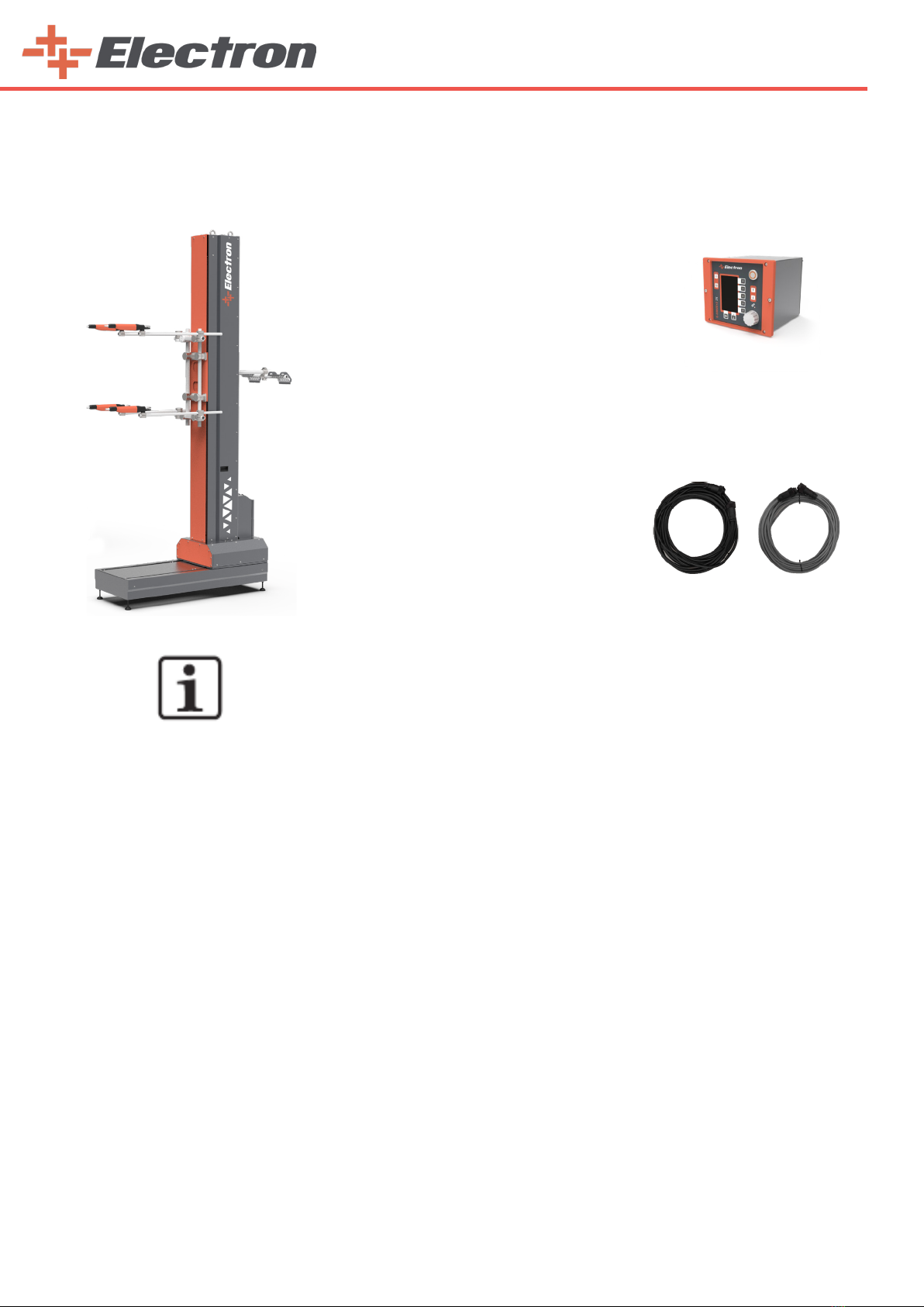
E-ROBOT+3 Z is the general name of a system. It is not a single product, but a combination of several produ-
cts.
E-ROBOT+3 Z;
2. Function description
2.1. Field of application
The E-ROBOT+3 Z Reciprocator was designed for automatic coating with powder applicators. It is used as the
basis for all stages of automation, from a simple vertical stroke to complex, multi-dimensional processes.
Depending on the design of the applicators, this unit may be used with all types of powder coating.
Any other use is considered non-compliant. The manufacturer shall not be liable for damage resulting from such use;
the user bears sole responsibility for such actions.
2.1. Field of application
The reciprocator carries out a linear, oscillating up-and-down motion in the vertical direction (called Z motion).
The movement sequences (stroke and stroke speed) are controlled by the reciprocator control unit.
The gun holders are fitted on the gun holder plate of the Z carriage. The Z carriage is moved up and down
on the central column by a drive belt inside the reciprocator. This vertical column serves also as a runway for the
rollers. The drive unit and the electrical connection are installed in the vertical axis base. A pulse generator, which
is installed in the motor case, enables the exact positioning of the Z carriage.
The power unit, as well as the corresponding wiring, are housed in an electronics module, which is plugged
into the axis. One module is needed for each axis. Empty space is available for additional axes (e.g. X axis).
If the power is interrupted, the movement of the Z-carrier according to the design is stopped by the logic
of mutual weight, ie the torque relationship.
NOTE:
Each product is ordered separately in order to order a reciprocator system. For ordering
steps, check the “Order” section on page 38.
E-ROBOT+3 Z
E-ROBOT+3 X
E-DRIVE Z02-EX
POWER & SIGNAL CABLES

11
2.4. Special Characteristics
The E-ROBOT+3 Z Reciprocator is conspicuous because of its rugged construction,
a new drive system and an improved Z axis carriage design.
Further characteristics:
•50 kg load capacity for automatic gun and gun holders
•Quiet running
•High speed, maximum acceleration and braking action
•Safe operation and simple maintenance
•High efficiency due to low energy consumption
•Designed for continuous operation
•TMobile version available
•IP54 protection type
•6 standard stroke heights available: 1.2 m/1.5 m/1.8 m/2.1 m/2.4 m/2.7 m
•Intermediate and larger sizes available in steps of 300 mm
2.5. Expansion with additional axes of motion
The E-ROBOT+3 Z Reciprocator is available, depending on operational
area, in six versions with different standard stroke heights.
2. 6. Reasonably foreseeable misuse
•Operation in rooms with gases (depends on the properties of the powder coating used.)
•Incorrect setting of the mechanical stroke limiters
•Incorrect programming of the upper and lower turning points
•Use in connection with not permissible control units
•Loading the Z carriage with more than 50 kg
•Operation without the proper training
•Operating the reciprocator without the protective fence
12
3.Technical Data
The E-ROBOT+3 Z Reciprocator is available, depending on operational area, in six versions with different
standard stroke heights.
3.1.Technical Data
*Vertical Axis
E-ROBOT+3 Z 1200 1500 1800 2100 2400 2700
Height 2,524 m 2,824 m 3,124 m 3,424 m 3,724 m 4,024 m
Stroke lenght 1,2 m 1,5 m 1,8 m 2,1 m 2,4 m 2,7 m
Belt 4,7 m 5,3 m 5,9 m 6,5 m 7.1 m 7.7 m
Order Code A05RD01200+3-X A05RD01500+3-X A05RD01800+3-X A05RD02100+3-X A05RD02400+3-X A05RD02700+3-X
Stroke Speed 0.1 up to 0.6 m/s (6.0 up to 36.0 m/min.)
Acceleration 0.5-2.5 m/s²
Position detection with incremental pulse generator
*Horizontal Axis
E-ROBOT+3 X Technical Values
Stroke lenght 1000 mm 1500 mm
Product Code A05X031000 A05X031500
Stroke Speed 0.06 up to 0.15 m/s (4.0 up to 8.0 m/min.)
Position Zero point selectable in both end positions
Position detection with incremental pulse generator
*Control Unit
E-DRIVE ZX02-E
Height 182 mm
Widht 220 mm
Depth 250 mm
Weight 3.34 kg
Product Code B08ZX02CM-E
3.2.Electrical Data
E-ROBOT+3 Z-Axis Reciprocator
Power supply 230 VAC (from control unit)
Tolerance ± 10%
Frequency 50/60 Hz
Protection Type IP54
Operating Temperature Range -10°C - +40°C
Max. Protection Surface Temperature 135°C
3.3.Sound Pressure Level
E-ROBOT+3 Z-Axis Reciprocator
Normal operation < 60 dB(A)
The sound pressure level was measured while the unit was in operation; measurements were taken at the most frequent oper-
ator positions and at a height of 1.7 m from the ground. The specied value is applicable only for this product itself and does
not take into account external noise sources or cleaning impulses. The sound pressure level may vary, depending on the product
conguration and space constraints.

13
4.Set-up, assembly and commissioning
WARNING:
If a free-standing reciprocator is not anchored firmly to the oor,
uncontrolled movement of the machine or insufficient stability can
cause injuries.
** Firmly anchor the reciprocator to the oor if it is not mounted to another axis of motion.
WARNING:
The movement of the reciprocator can cause injuries.
** Erect a protective fence around the reciprocator so that there is no danger of injury during nor-
mal operation.
DANGER:
Injuries can occur inside the protective fence due to the movement of the reciprocator!
** In order to enter the inner area, the door interlocks must be released by the control unit. This
release signal may only be activated by technical personnel.
DANGER:
Injuries can occur inside the protective fence due to the movement of the reciprocator!
** In order to enter the inner area, the door interlocks must be released by the control unit.
This release signal may only be activated by technical personnel.
Except for normal operation, all other operating modes must be set up by an authorized technical representative.
4.1.2 Setup and assembly
4.1.1 Preparation for start-up
Except for normal operation, all other operating modes must be set up by an authorized technical representative.
•Open The Base Top Covers
Consists of 2 parts. There are 2 bolts on the middle point of each cover. Use an 4 mm allen key.
WARNING:
Before connecting or switching on the reciprocator, read carefully these operating
instructions!
WARNING:
f a free-standing reciprocator is not anchored firmly to the oor, uncontrolled movement of
the machine or insufficient stability can cause injuries.
** Firmly anchor the reciprocator to the oor if it is not mounted to another axis of motion.
WARNING:
The movement of the reciprocator can cause injuries.
** Erect a protective fence around the reciprocator so that there is no danger of injury during
normal operation.
14
•Place Horızontal Unit Accordıng To The Project Values.
Make sure the base is on a at oor. Use M16 xing plug.
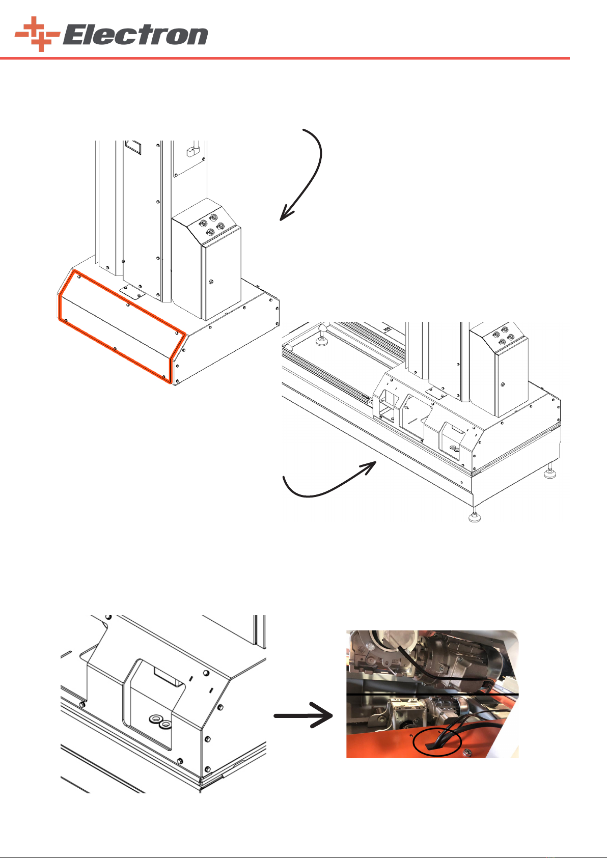
•Open bottom side covers of the reciprocator.
4.1.3. Connecting the E-ROBOT+3 X Horizontal Motion Unit to the Z Reciprocator
1. Ensure that the cables are routed at the specied points to avoid crushing the cables. (Motor, encoder and
sensor cables)
• Position the reciprocator on the
base of the horizontal unit.

15
2. Remove the back cover of the reciprocator (vertical axis). Route the cables through the cable holes (1) of
the junction box mounted on the cover. (as shown in the picture)
3. Connect the cable (according to the enclosed wiring diagram)
NOTE:
After positioning, the E-ROBOT+3 X Horizontal Motion Unit must be firmly fixed on the oor.
DANGER:
Never stand on the horizontal axis or under the carriage of the vertical axis when it is in ope-
ration!
WARNING:
- The power of the horizontal axis is much stronger than that of a human!
- All axes must be secured against admittance during operation (see local regulations).
Before start-up the horizontal axis, the following points must be observed:
- The frame and the drive carriage of the axis must be grounded! The grounding of the frame
must be done by the customer.
- Adjust the system parameters in the E-Drive control unit.
1

16
5.Commissioning
5.1. Preparation for start-up
WARNING:
Before connecting or switching on the reciprocator, read carefully these operating
instructions!
Before the reciprocator is put into operation, the upper stroke limit must be set on the
reciprocator control unit!
WARNING:
Before start-up works are done, make certain that nobody can
switch on the reciprocator! Switch off and lock the mains switch!
Before starting up, the following checks should be done:
• Check the gun holder and hose holder if they are firmly fitted.
Mount the gun holder in such a way that they do not hit the bottom of the booth
slots on start-up and cause damage
• Lay out the cables and hoses in such a way that even at the highest stroke no strain
can arise
• Check the grounding of the guns and hose carriers
• Check if the upper and the lower reversing point of the Z carriage are set
correctly. The stroke length of the reciprocator must be in the range of the booth
opening (collision danger!)
• Make sure that the automatic guns cannot collide with the work pieces
(incorrectly adjusted stroke parameters on the reciprocator control unit)
5.1.1. General information
5.1.2. Reference point
5.1.3. Horizontal Axis Reference point
At every start-up after the mains have been interrupted, the reference point of the reciprocator must be refer-
red again (see “Reference point and mechanical stops”). After the reference point is reached, the reciprocator begins
to carry out the movements set on the reciprocator control unit.
Before the reciprocator is put into operation, the upper stroke limit must be set on the reciprocator control
unit!
The reference point of the horizontal axis is selected when the sensor passes mechanical stop bumper by 2
mm. This is a factory setting. It will be set and sent. Unless necessary, do not pull by manually adjusting the move-
ment mechanism of the horizontal axis.
WARNING:
Incorrect setting of the upper and lower stroke limits can cause
damages to the reciprocator, to the booth and/or to the applicators!
WARNING:
In order to avoid damages to the booth or the gun holder etc. the reference point must be
set by Electron authorized person before the first start-up!

17
5.2. Connections
Electrical connections / cable connection
E-DRIVE ZX02-E
First Reciprocator Second Reciprocator
Electrical connections of E-ROBOT+3 Z;
Power supply cable (black) and signal cable (white) are connected between the E-DRIVE control unit and the
control unit on the reciprocator. For each reciprocator to be added from now on, power and signal connections are
made from the empty slots of the previous reciprocator with the same type of cables.
NOTE:
To order different lengths of cable, see “Ordering” on page 38.
5.3. Checkpoints before switching on
Before switching on, the following checks should be done:
• Check if the cables and hoses are laid out correctly
• Check if the guns have a clear run and do not touch the booth slots
• Check the distance between the work pieces and the guns
WARNING:
Before connecting or switching on the reciprocator, read carefully these operating
instructions!
5.4. Grounding / protection type
All metal parts of the reciprocator must be grounded according to the local safety regulations. The gun hol-
ders must be connected to the grounding screw on the reciprocator base by the grounding strip.
All electrical installations are implemented in accordance to IP54 protection type regulations!
• See the section 12)
Grounding Diagram.
5.5. Hoses and cables
All movable hoses and cables must be laid out in such a way that they are neither subjected to any loads nor
can hang on other parts. The electric cables of the reciprocators must be protected from mechanical damage.
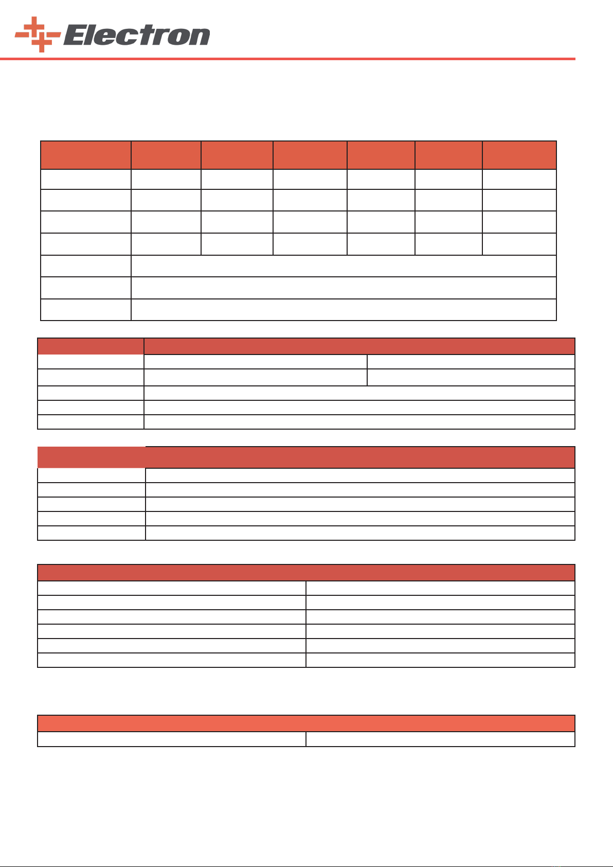
Order Code Part Name
B08ZX02SC-E10 E-DRIVE ZX02-E RECIPROCATOR SIGNAL CABLE - 10 MT
B08ZX02SC-E15 E-DRIVE ZX02-E RECIPROCATOR SIGNAL CABLE - 15 MT
B08ZX02SC-E20 E-DRIVE ZX02-E RECIPROCATOR SIGNAL CABLE - 20 MT
B08ZX02SC-E25 E-DRIVE ZX02-E RECIPROCATOR SIGNAL CABLE - 25 MT
Order Code Part Name
B08ZX02PC-E10 E-DRIVE ZX02-E RECIPROCATOR POWER CABLE - 10 MT
B08ZX02PC-E15 E-DRIVE ZX02-E RECIPROCATOR POWER CABLE - 15 MT
B08ZX02PC-E20 E-DRIVE ZX02-E RECIPROCATOR POWER CABLE - 20 MT
B08ZX02PC-E25 E-DRIVE ZX02-E RECIPROCATOR POWER CABLE - 25 MT

18
5.6.1. Setting the reference point
1.Move the stop plate with rubber buffer and proximity switch to the desired position and fasten it
2. Set the response gap of the proximity switch to approx. 2 mm
3. Consider the lower edge of the gun slot!
WARNING:
In order to avoid damages to the booth or the gun holders, the reference point must be checked
before the first start-up and if necessary, reset!
It must be noted that the axes in reference travel moves up to 25 mm below the control’s zero
point, therefore the mechanical stop must be set in accordance to the gun slots!
The position of the upper and the lower stop plate is set by a Electron service engineer
when the reciprocator is assembled.
WARNING:
The reference point must be referenced before each start-up (at each switching on, after an
interruption of the power supply etc.)!
WARNING:
The setting of the lower mechanical stop must take place without load and the reciprocator
must be disconnected from mains!
Procedure:
1. Let the Z carriage sink down until the powder gun holder is
approximately 50 mm above edge of the gun slot
2. Remove the boarding/side panels
3. Loosen the screws and move the lower stop plate up to the Z carriage
4. Tighten the screws
5. Refit the boarding/side panels
WARNING:
The setting of the upper mechanical stop must take place without load and the reciprocator
must be disconnected from mains!
5.6.2. Setting the lower mechanical stop
5.6.3. Setting the upper mechanical stop
In order to set the upper mechanical stop, the stop position hast to be measured -
for this reason, consider the maximum height of the booth gun slots!
WARNING:
An incorrect (too high) set stroke limit can lead to damage to the reciprocator and/or the booth!
Procedure:
1. Remove the boarding/side panels
2. Loosen the screws and move the upper stop plate up to the measured position
3. Tighten the screws
4. Refit the boarding/side panels
WARNING:
After the adjustment of the mechanical stops, the system parameter for the upper stop must be
checked on the reciprocator control unit!
The value must not be larger than the maximum stroke possible between the stops!
WARNING:
Incorrect setting of the upper and lower stroke limits can cause damages to the
reciprocator, to the booth and/or to the applicators!
The reference point serves as starting point for the reciprocator control unit for calculating the upper and
lower reversing point and the maximum stroke.
By switching on the axis control unit, the reciprocator travels automatically to the reference point (proximity
switch). The reciprocator control units are programmed in such a way that the reference point is
always located 50 mm above the reversing point.
For transport reasons, the E-ROBOT+3 Z Reciprocator is delivered with the rubber buffer and the carriage
in lowest position.
5.6. Reference point and mechanical stops

19
6.Start up preferences
After the power button on the back end of the control unit is turned on, pressing the power button on the front
screen turns on the system. When there is an error in the Reciprocator, it writes the error code on the left side of
the page and warns the operator. Please refer to the “Error Codes Section” for error scenarios.
After the start up procedure, the “Main Menu” page will be seen on the screen. When the ‘‘Main Menu’’ appears on
the display the operator can start using the reciprocator.
At the end of the start up procedure, the mechanical unit drives down to the reference point (zero point). The Z
carriage travels to the mechanical stop, hitting the rubber buffer and then saves the point as reference for the
operation.
Zero Point Sensor/Rubber Buer
6.1. Electrical Connections
6.2. Simple General Purpose AC Drive Settings
Make connections according to Section 11 Electrical Schematic Diagram.
Mechanical Stop Bumber
Zero-Point Reference Sensor

20
6.2.1. Basic Parameters
In order for the robot to work properly, you should make the adjustments given in the table below in the
motor driver located on the panel behind the robot. Here are the steps you need to follow to make the adjust-
ments:
1)Press the ‘‘prog/data’’ button. “1-” will appear on the screen.
2)Press the ‘‘prog/data’’ button once again. “1-00” will appear on the screen.
3)Press the ‘‘prog/data’’ button once again. We do this process to get into the parameter.
4) Press until you reach your desired value without raising your hand. (For example, do not lift our finger
until you see ‘‘75 .0’’ for parameter 1-00.)
5)Press the ‘‘prog/data’’ button once. “END” appears momentarily on the display. You will have saved the
parameter value. And the number of parameters will appear on the screen again.
6)Press the button once to go to the next parameter.
7)Press the ‘‘prog/data’’ button. We do this process to get into the parameter.
8)Apply all operations for each parameter as from item 4.
9)After saving all the parameter values, press the ‘‘mode/reset’’ button twice and return to the main menu.
NOTE:
The same parameters are set for all driver.
WARNING:
Ground the AC DRIVE using the ground terminal . The grounding method
must comply with the laws of the country where the AC drive is to be installed.
E-DRIVE ZX02-E (ROBOT 220 V)
VERTICAL SPEED CONTROL HORIZONTAL SPEED CONTROL
PARAMETERS FACTORY
SETTINGS
Sengs For
E-ROBOT+3 Z PARAMETRELER FACTORY
SETTINGS
Sengs For
E-ROBOT+3 X
1.00 60.00 Hz 75 1.00 60.00 Hz 75
1.01 60.00 Hz 75 1.01 60.00 Hz 75
1.02 220.0 V 230 1.02 220.0 V 230
1.03 1.50 Hz 50 1.03 1.50 Hz 50
1.04 10 V 230 1.04 10 V 230
1.19 00 1 1.19 00 1
2.00 00 3 2.00 00 3
2.01 00 2 2.01 00 2
2.05 01 0 2.05 01 0
4.05 01 5 4.05 01 5
6.03 00 2 6.03 00 2
6.04 % 150 90 6.04 % 150 90
6.05 0.1 Sec 1 6.05 0.1 Sec 1
7.00 4.2 1.8 7.00 4.2 1.2
7.01 1.7 1.7 7.01 1.7 1.1
7.02 0.0 9 7.02 0.0 9
8.00 % 0 35 8.00 % 0 35
8.02 0.0 Sec 0.5 8.02 0.0 Sec 0.5
9.02 03 1 9.02 03 1
9.04 00 3 9.04 00 3
This manual suits for next models
6
Table of contents
Popular Industrial Equipment manuals by other brands

SAC
SAC MAXI-MIXER 4750 Operator's manual

Jäger
Jäger Z80-K440.21 S4 manual

Mennekes
Mennekes AMAXX Installation and operating manual

Mec
Mec 408 owner's manual

Endress+Hauser
Endress+Hauser 51517656 CleanFit H CPA 475 operating instructions

RINGSPANN
RINGSPANN FRS Series Installation, Lubrication, Maintenance Instructions


