Electronic Secretary DCR-1 User manual
I
MANUAL
FO
R
CkcDz.an.ic
Model
DCR-1
ISSUE
E
JULY
1957
DESC
RIPTION
INSTALLATION,
CO
NNECTION
AND
MAINTENANCE
I
NFO
RMATION
ELECTRONIC
SECRETARY
INDUSTRIES INC. 1101 So.
Prairie
Ave.
•
Waukesha,
Wisconsin
TCI Library www.telephonecollectors.info

Table
of
Contents
ELECTRONIC
SECRETARY
Model
DCR-1
ENGINEERING
SERVICE
MANUAL
Section
CD
@
@
©
®
@
CV
@
®
DESCRIPTION, INSTALLATION AND CONNECTIONS
GENERAL OPERATING
PRINCIPLES
WITH 8
SCHE-
MATIC DRAWINGS
DESCRIPTION
OF
BASIC COMPONENTS
GENERAL MAINTENANCE PROCEDURE
SUMMARY
OF
MAINTENANCE CALLS
AND
SUG-
GESTED MEASURES
FOR
HANDLING
TABLE
OF
VOLTAGE READINGS
ADJUSTMENT
OF
RECORD
PLAYER
MECHANISM
ADJUSTMENT
OF
WIRE RECORDER MECHANISM
PARTS LIST
TCI Library www.telephonecollectors.info

TCI Library www.telephonecollectors.info
DESCRIPTION,
INSTALLATION
AND
CONNECTIONS
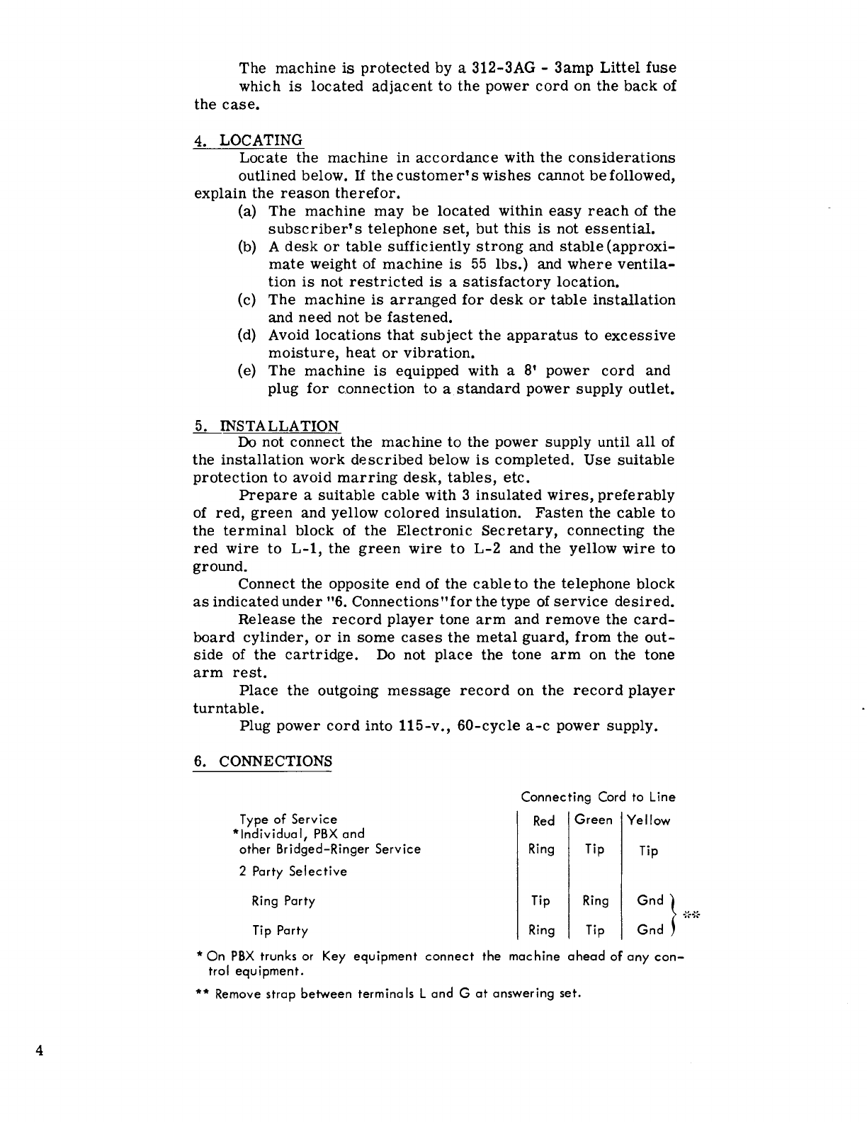
1. DESCRIPTION
The model DCR-1
Electronic
Secretary
is
a machine
used
to
furnish
automatic telephone
answering
and
recording
service
on
central
office and PBX
lines.
It
can be
used
on individual
lines
and 2 and
4-party
selective
lines,
and
is
the equivalent of 1
ringing
bridge.
The machine
is
arranged
to
respond
to
an incoming
call
with an announcement
message,
followed by a tone
signal,
a
period
for
recording
a
message
and then a "ThankYou"
or
sign-
off
message.
The
maximum
total
time
for
each
call
is
approxi-
mately
3
minutes,
which
can
be
divided into any length of
an-
nouncement
plus
recorded
message
plus
sign-off
message.
The
machine
consists,
basically,
of a modified
record
player,
a
wire
recorder
and an
amplifier
and loud
speaker.
A
vinylite
record,
containing a
standard
message,
is
normally
supplied.
Records
containing a
specific
announcement,
recording
period
and
sign-off
messages
may
be
obtained.
This
record
is
the
timer
for
the
entire
operation.
The
wire
recorder,
which
starts
immediately
following the tone
signal,
will
accept
messages
up to a
total
of about60 minutes,
after
which the machine will not
respond
to incoming
calls.
The
automatic
restoral
of the
record
player
arm,
after
completion of the
sign-off
message,
electrically
resets
the machine,
releasing
the
line
for
the
next incoming
call.
2. TRANSPORTING
The
machine should
be
handled
carefully
at
all
times
to
avoid damage.
Before
transporting
the
machine
always:
(a)
Secure
the
record
player
tone
arm
by tying
it
to
its
bracket
with
lacing
cord.
(b)
Remove the vinylite
record.
(c)
After
rewinding
the
wire
to the
small
spool, which
may
require
operating
the
"Automatic Stop
Reset"
button,
remove
the
large
and
small
wire
spools.
3. POWER SUPPLY
The
machine
is
designed
to
operate
on 115-volt,
60-cycle,
a-c
power
supply.
In
no
case
should the machine
be
direct-
ly
connected to
direct
current.
If
only
d-c
current
is
available,
ref
er
the
matter
through
regular
organization
channels
to
the
Engineering
Department
for
advice
before
proceeding
with
the
installation.
Section
CD
3
TCI Library www.telephonecollectors.info
4
The
machine
is
protected
by a 312-3AG -
3amp
Littel
fuse
which
is
located
adjacent
to
the
power
cord
on the
back
of
the
case.
4. LOCATING
Locate
the
machine
in
accordance
with
the
considerations
outlined below.
If
the
customer's
wishes
cannot
be
followed,
explain the
reason
therefor.
(a)
The
machine
may
be
located
within
easy
reach
of
the
subscriber's
telephone
set,
but
this
is
not
essential.
(b) A
desk
or
table
sufficiently
strong
and
stable
(approxi-
mate
weight of
machine
is
55
lbs.)
and
where
ventila-
tion
is
not
restricted
is
a
satisfactory
location.
(c)
The
machine
is
arranged
for
desk
or
table
installation
and need not
be
fastened.
(d) Avoid
locations
that
subject
the
apparatus
to
excessive
moisture,
heat
or
vibration.
(e)
The
machine
is
equipped with a
8'
power
cord
and
plug
for
connection
to
a
standard
power
supply outlet.
5. INSTALLATION
Do not connect the
machine
to
the
power
supply
until
all
of
the
installation
work
described
below
is
completed.
Use
suitable
protection
to
avoid
marring
desk,
tables,
etc.
Prepare
a
suitable
cable
with 3
insulated
wires,
preferably
of
red,
green
and yellow
colored
insulation.
Fasten
the
cable
to
the
terminal
block of
the
Electronic
Secretary,
connecting
the
red
wire
to
L-1,
the
green
wire
to
L-2
and
the
yellow
wire
to
ground.
Connect the
opposite
end
of the
cable
to
the
telephone
block
as
indicated
under
"6.
Connections"for
the
type of
service
desired.
Release
the
record
player
tone
arm
and
remove
the
card-
board
cylinder,
or
in
some
cases
the
metal
guard,
from
the
out-
side
of
the
cartridge.
Do not
place
the tone
arm
on the tone
arm
rest.
Place
the outgoing
message
record
on
the
record
player
turntable.
Plug
power
cord
into
115-v.,
60-cycle
a-c
power
supply.
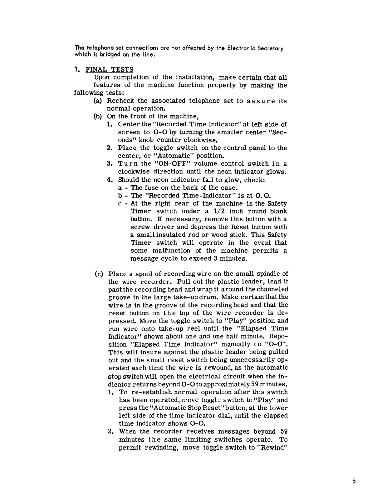
6. CONNECTIONS
Connecting
Cord
to
Line
Type
of
Service
Red
Green
Yellow
*Individual,
PBX
and
other
Bridged-Ringer
Service
Ring Tip Tip
2 Party
Selective
Ring Party Tip Ring
:::
}
%{}
Tip Party Ring Tip
*On
PBX
trunks or Key
equipment
connect
the
machine
ahead
of
any
con-
trol
equipment.
** Remove
strap
between
terminals
Land
G
at
answering
set.
TCI Library www.telephonecollectors.info
The
telephone set connections are not affected
by
the Electronic Secretary
which
is
bridged
on
the Iine.
7. FINAL TESTS
Upon
completion
of
the
installation,
make
certain
that
all
features
of the machine function
properly
by making the
following
tests:
(a)
Recheck
the
associated
telephone
set
to
assure
its
normal
operation.
(b) On the
front
of the machine,
1.
Center
the
"Recorded
Time
Indicator"
at
left
side
of
screen
to
0-0
by
turning
the
smaller
center
"Sec-
onds"
knob
counter
clockwise.
2.
Place
the toggle
switch
on
the
control
panel
to
the
center,
or
"Automatic"
position.
3.
Turn
the
"ON-OFF"
volume
control
switch
in
a
clockwise
direction
until the neon
indicator
glows.
4. Should the neon
indicator
fail
to
glow, check:
a - The
fuse
on the
back
of
the
case.
b - The
"Recorded
Time-Indicator"
is
at
0.
O.
c - At the
right
rear
of
the machine
is
the Safety
Timer
switch
under
a
1/2
inch
round
blank
button.
If
necessary,
remove
this
button with a
screw
driver
and
depress
the
Reset
button with
a
small
insulated
rod
or
wood
stick.
This
Safety
Timer
switch
will
operate
in
the
event
that
some
malfunction of the machine
permits
a
message
cycle
to
exceed
3
minutes.
(c)
Place
a
spool
of
recording
wire
on the
small
spindle
of
the
wire
recorder.
Pull
out the
plastic
leader,
lead
it
past
the
recording
head and
wrap
it
around
thechanneled
groove
in
the
large
take-up
drum.
Make
certain
that
the
wire
is
in
the
groove
of the
recording
head and
that
the
reset
button on
the
top of the
wire
recorder
is
de-
pressed.
Move the toggle
switch
to
"Play"
position and
run
wire
onto
take-up
reel
until the
"Elapsed
Time
Indicator"
shows about one and one half minute. Repo-
sition
"Elapsed
Time
Indicator"
manually
to
"0-0".
This
will
insure
against
the
plastic
leader
being pulled
out and the
small
reset
switch
being
unnecessarily
op-
erated
each
time
the
wire
is
rewound,
as
the automatic
stop
switch
will open
the
electrical
circuit
when the
in-
dicator
returns
beyond
0-0
to
approximately
59
minutes.
1.
To
re-establish
normal
operation
after
this
switch
has
been
operated,
move toggle
switch
to
"Play"
and
press
the"Automatic Stop
Reset"
button,
at
the
lower
left
side
of
the
time
indicator
dial, until the
elapsed
time
indicator
shows
0-0.
2. When the
recorder
receives
messages
beyond
59
minutes
the
same
limiting
switches
operate.
To
permit
rewinding, move toggle
switch
to "Rewind"
5
TCI Library www.telephonecollectors.info

6
and
press
the automatic stop
reset
button until the
elapsed
time
indicator
shows
58
minutes.
(d)
Call the
test
desk
and
request
the deskman to make a
test
call
tochecktheannouncementand
leave
a
message.
(e) Move the toggle switch to the left,
or
"Rewind" position.
The
indicator
will
start
forward
and then, within a
sec-
ond
or
two,
reverse.
Leave the switch in the "Rewind"
position until the
indicator
returns
to
"0•0".
(f) Move the toggle switch to the
extreme
right
or
"Play-
back" position,
operate
Automatic Stop
Reset
button,
and advance the"Volume"
control
to check
for
record-
ing of
received
message
and
for
sufficient playback
volume.
(g)
Erase
the
test
message
by rewinding
the
wire
with the
erase
button
depressed
until the elapsed
time
indicator
shows
0-0.
(h)
The machine
is
now
in
the
correct
position
for
the
sub-
scriber's
use. Whenthe
service
is
not
desired
turn
the
"Volume"
control
to
"Off"
and neon
lamp
will
cease
to
glow.
TCI Library www.telephonecollectors.info
Section
GENERAL
OPERATING
PRINCIPLES
What It
Is
Basic
Timing
Start
and
Stop
MU
Switches
On
Record
Player
What
Is
Re-
quired
To
Start
A Cycle
Of
Automatic
Operation
How
The
Tele-
phone Ring
Starts
The
Re-
cord
Player
Motor -
Trig-
ger
Action
Relay
Contacts
Involved: 3b
The
Electronic
Secretary
is
an
automatic
telephone
an-
swering
machine,
consisting
of
several
electronic
amplifiers
whose
operating
periods
are
governed
by
simple
electrical-
mechanical
sequence
switching. The
harmonious
co-functioning
of
these
basically
different
systems
provide
a
simple,
yet
com-
pletely
satisfactory
method of telephone
answering,
requiring
a
minimum
amount of
adjustment
from
one
operating
condition
to
another.
Basically
the
timing
device
used
in
Electronic
Secretaries
to
control
the
activity
sequence
of
the
various
amplifiers
is
the
outgoing
message
disc
or
record;
and
the
record
player
associated
with
it
provides
the
mechanical
power
for
the
basic
switching
actions.
The
record
player
has
attached
to
its
repeated
mechanism
a
pair
of
very
low
operating
pressure
switches,
which
close
as
the
tone
arm
lowers
itself
to
the
record
to
begin
a
cycle
and
opens
as
the tone
arm
travels
through
the
throw-out
grooves
and
resets
itself,
to
end
a
cycle.
We
see
therefore
that
the
basic
time-switching
operation
of
starting
and
stopping
the
machine
is
performed
by two
simple
switches
attached
to
the
record
player;
the
duration
of the
operating
cycle
is
determined
by
the
length of
time
to
which
the
record
is
cut.
From
the above
observation
we
learn
that
all
that
is
re-
quired
to
place
the
machine
into
operation
would be to apply
cur-
rent,
when the telephone
rings,
to
the
record
player
motor,
for
a
period
long enough
for
it
to
close
its
own
switches,
which
as
we
learned
in the
preceding
paragraph,
close
when the tone
arm
sets
down upon
the
record.
This
current
of
course
will
be
cut
off when the tone
arm
resets
to end the
operating
cycle.
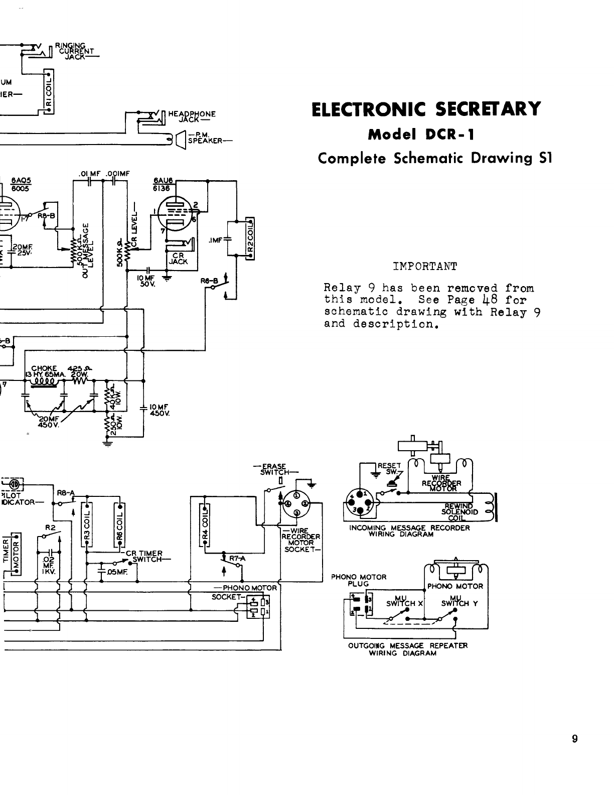
To
comprehend
fully how
the
telephone
ring
automatically
starts
the
record
player,
we
can
refer
to
schematic
diagrams
S1
and S2.
You
will
note
that
diagram
S2
is
merely
a
part
of
dia-
gram
S1,
whichhas
been
literally
lifted
out of
the
complete
sche-
matic
to
show
and
isolate
the
triggering
action.
Looking
at
S2
closely,
we
see
that
one
side
of the telephone
terminal
block
is
connected
through
a 2
microfarad
condenser
to a
selenium
bridge
rectifier,
and
the
other
side
of the telephone
line
is
connected
through
the
normally
closed
contacts
3b,
through
a 100 ohm
fusing
resistor
to
the
other
input point of
the
selenium
bridge.
The output of
the
bridge
rectifier
feeds
a 2500 ohm
D.
C.
relay
thru
a
metering
jack.
It
is
this
relay,
R1
whose
contacts
apply
current
to
the
record
player
motor
whenever
the
relay
is
ener-
gized
by
the
rectified
ringing
current
of the telephone.
7
TCI Library www.telephonecollectors.info

8
Lt~
~~----~~~~~~~~~~~~~~~~~~--~
G
~1:..._~~~~~~~~~~~~~~~~~~--J
OSCILLATOR
COIL
35
KC.
-PLAYBACK
.
LEVEL
CONTROL-
IOMF.
I450V
.
..
-SELECTOR
R3-B
20MF.
25V.
POWER
TRANS-
FORMER
2.0MF
.OIMF
I
KV.
R4-A
-AUTO
STOP
RESET
SW.-
..
WIRE RECORDER
1-EAD
SOCKET-
SWITCH-
c II r
-RECORD-REPRODUCE
HEAD-
z
~
a:
~
...J
Q.
'-
-NEOI
RI
117\1
60N-l....l---------.------.E-~------i;:--
.......
-------Ol.._
____
.:..:..:.:.;;..;..,E--
NOTE:
Relay
contacts
are
read
from
left
to
right
facing
terminal
board
of
relay.
"A"
contacts
to the
left
and
"B"
contacts
to the
right.
TCI Library www.telephonecollectors.info
UM
~
IER-
__
__,rt!
~HE1£t~ONE
----------
3
CJ
sfE~KER-
~OMF.
5 25V·
.
.01
MF"
.0
IMF
LLI
C)
i
-----~
'°1-.J
a
____
J
'!LOT
DICATOR-
IOMF
50V.
CR
JACK
IOMF
450V.
[~]
ELECTRONIC
SECRET
ARY
Model
DCR-1
Complete Schematic
Drawing
51
-ERASE
SWITCH-
Q
-WIRE
RECORDER
MOTOR
SOCKET-
IMPORTANT
Relay
9
has
been
removed
from
this
model.
See Page
48
for
schematic
drawing
with
Relay
9
and
description.
RESET
"r
7
PHONO
MOTOR
PLUG
PHONO
MOTOR
a;
-e.H
X
s..Ji1ti'CH
Y
.c,;.
_____
,,
OUTGOllG
MESSAGE
REPEATER
WIRING DIAGRAM
9
TCI Library www.telephonecollectors.info
10
Relay Contact
of Relay 1
Switches
115 V.A.C.
To Record
Player
Motor
Electrical
Action of the
MU-Switches
on the
Record
Player
How
The
Machine'
Answers The
Phone
Function of
Relay 3
Function of
Relay 6
If
we
now
ref
er
momentarily
to
diagram
S7
we can
see
how
current
from
the hot side of the power line
travels
through the
3
ampere
fuse, power switch connected to the volume control
shaft, safety
timer
switch,
normally
closed
contact
of
relay
con-
tact
7b,
normally
closed
contacts of
limit
switch on
elapsed
time
indicator through the contacts of
relay
1 when
closed
to pin 3
of
the 4 pin Jones phono
motor
socket.
Pin
3 through the plug that
fits
this
socket leads to the hot
side
of the
record
player
motor.
This action
of
contact of
relay
1 closing
is
called
"triggering"
and
relay
1
is
called
the
triggering
relay.
We
have
now
seen
the
electrical
effect of
relay
1 in
start-
ing the
record
player
and the action of the low
pressure
MU-
switches in closing, thus
starting
a cycle. The effect of closing
these
two switches
is
to
short
pins 1 to 3 and 3
to
4 on the 4 pin
phono
motor
socket
(refer
to
diagram
S7
).
This action
in
effect
advances
current
from
the hot side of the line
across
the
con-
tacts
of
relay
1 to hold the
record
player
motor in continuously;
and the shorting of pins 3 to 4 of the second
record
player
MU
switch advances
current
to the
coils
of
relay
3 and
relay
6.
You
will note
from
diagram
S7
that
the
coils
of
these
two
relays
get
their
neutral
feed through the normally
closed
contacts
of
relay
Sa. In the play-back
or
rewind position of the
selector
con-
trol
switch
current
will
of
course
be brought to the
coil
of
relay
8 and the
neutral
path to
relays
3 and 6 will be broken.
We
see
however that in the automatic position closing of
the contacts of
relays
3 and 6 will in effect
answer
the phone
in
the following
manner:
Referring
to
diagram
S, we
see
that
in
the stand-by automatic position, contact 3b of
relay
3
is
connect-
ing one
side
of the telephone line to the
selenium
rectifier
bridge,
through 1
oo
n fusing
resistor
while
relay
contact
3a
is
connecting the output
of
the audio output
transformer
to the loud-
speaker
voice coil. When
relay
3
is
energized
however,
these
normally open contacts
close
and the effect of contact 3b
is
to
lead
from
one side of the input line
transformer
to one
side
of
the telephone line, while
at
the
same
time
contact
3a
will switch
one
side
of the audio output
transformer,
and the line input
trans-
former
with
their
secondaries
in
series
will be thrown
across
the telephone line. The effect
of
this
loading will be
the
same
as
answering the phone in the coventional
manner.
The function of
relay
6 in
this
operation
is
twofold. Con-
tact
6a opens
at
this
time
to remove an .01
by-pass
condenso:ia
from
the plate of the
6AQ5
tube,
as
this
condensor while
desir-
able in the playback
operation
of the
amplifier
tends
to muffle
the
speech
during the outgoing
message
phase of automatic
operation. Relay contact 6b
closes
also
at
this
time
to supply
d.c. voltage to
relay
2 and the
6AU6
tube
associated
with
its
operation.
At
this
point
we
are
now
in cycle and
transmitting
an
out-
going
message.
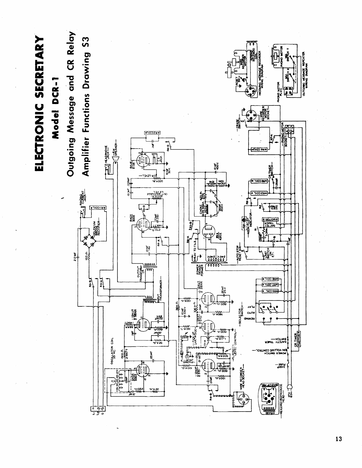
The outgoing
message
path can be
seen
clearly
in
diagram
S3, outgoing
message
and
CR
action. To fully under-
TCI Library www.telephonecollectors.info

.......
.......
~n
;!!!============================
........
~--+---.
CISCft"~
COIL
~I
~~
·~-
2.0MF
100.A.
ILECIRONIC
SECRETARY
Model
DCR-1
Answering and Line Loading
Functions Drawing 52
~
..aMll
ll!l'UTl!R
--
)
TCI Library www.telephonecollectors.info
12
How
The
Rec-
ord
Player
Transmits
The
Outgoing
Mes-
sage
Over
The
Telephone
The CR Action
How
It
Works
What
It
Does
Electronic
and
Electrical
Operation
of
CR
Electrical
Operation
of
CR
stand
this
action
we
can
take
a
pencil
and follow a
signal
from
the
phonograph
record
as
it
enters
the
amplifier
at
a
paint
marked
phono
tip
Jack
on
diagram
S3. The
signal
is
carried
thru
the
normally
closed
contact
of
relay
5a
to
the
grid
of
the
12AX7
(second
section)
through
one
section
of
the
12AU7
from
where
it
travels
through
the outgoing
message
volume
control
potentiometer
and the
normally
closed
section
of
relay
contact
Sb
to
the output tube 6AQ5.
From
the outputof
this
tube
it
travels
through
the two
secondaries
of
the
output and input
transformer
in
series
and
is
impressed
on the telephone
line
through
the
con-
tacts
of
relay
3 now
closed.
We
are
now sending out
an
outgoing
message
in
which
the
answering
machine
first
identifies
itself
to
the
calling
party,
eventually
directing
him
to
leave
his
message
in
some
such
man-
ner
as,
"at
the
end
of the tone
signal,
please
begin speaking."
Now
let
us
refer
to
diagram
S3
to
study
what
happens
as
this
di-
rective
is
given, both
electronically
and
electrically.
First
of
all,
retracing
the
audio
path
through
the
normally
closed
contacts
of
relay
5a
to
the
grid
of the
second
section
of
voltage
amplifier
tube 12AX7
to
and
through
the
second
voltage
amplifier
tube
12AU7.
The output
plate
of
the
12AU7
feeds
up
to
a junction point,
where
it
goes
in
one
direction
through
an
.01
condensor
to
the
audio
output
stage
6AQ5
and
through
an
.001
condensor
to
the
relay
tube 6AU6. It
is
the
function of
this
latter
tube in which we
are
now
interested,
in
order
to
obtain
"CR
action"
which
in
ordinary
English
means:
A.
Starting
and stopping
the
wire
recorder
mechanism
at
the
proper
time.
B. Muting the outgoing
message
at
the
proper
time
so
that
there
will
be no
background
noise
from
the outgoing
message
amplifier
in
the
recordings.
C.
Switching
plate
voltage
to
the
record
pre
-
amplifier
tube (12AU7) and the
oscillator
tube (aAQ5).
Refer
to
diagram
S3.
Now
these
functions of
the
CRaction
are
accomplished
as
follows.
All audio
impulses
leaving
.the
record
disc
will
show up
at
both
the input of the 6AQ5 audio output
stage
and
at
the
input of
the
6AU6
relay
tube
stage.
However
the
effect
on the
relay
tube
stage
will
be
to
energize
the
relay
R2
for
relatively
short
inter-
vals.
This
action
will
allow the
contacts
of
R2
to
close
momen-
tarily
and
place
115 V.A.C. on the CR
motor
shown
in
diagram
S7.
We
see
from
this
diagram
that
this
power
is
obtained
from
pin 4 of
the
phono
motor
socket,
which now
has
power,
since
the
machine
is
in
cycle.
However
since
the
small
motor
shaft
is
spring
loaded,
it
cannot
advance
far
before
the
power
is
again
removed.
However, when the
steady
tone
is
emitted
from
the
record,
the
relay
R2
will hold
in
steadily
for
the
duration
of
the
tone, which
is
the
allotted
re·~ording
period.
This
advances
the
motor
and
earn
until
it
stalls
against
the
MU
switch
which
is
at-
tached
to
the
motor
and
c::m
a3sembly.
The
MU
switch
brings
TCI Library www.telephonecollectors.info
.....
(,.)
ELECTRONIC
SECRET
ARY
Model
DCR-1
'
a.~Mf
-------.
I
•OOA
RC._L
Outgoing Message
a·nd
CR
Relay
Amplifier Functions
Drawing
53
~~t=I
==--=====:!:
~
-RE:CORO~~oua;
osc!'Ht°"
co1L
~
x
0
g
,.I
!I
a:
JI
H
.n.
IOM•
~
f"°v
~
HEA_&~~E
.-~~~~~~~~~~~___,,...-~~~~~~~CJs~-
...
"
q:IJ
l~
F-<.__--~
il
-~
a
~~-1.,.)
1
~
• l l 1
••
_,..,. 4 I 4 ( * f l ( f9tw
TCI Library www.telephonecollectors.info

14
Relay 4
and 9
Their
Function
In
The CR
Action
How
Machine
Resets
To
End A Cycle
Of
Automatic
Operation
The Machine
Drops
Olt
Of
The Automatic
Cycle
115 V.A.C.
to
the
wire
recorder
motor
and
also
to
the
coil
of
re-
lay 4 through the
closed
contacts
of
relay
7a. The
energizing
of
relay
4 does the following. Ref
erring
back to
diagram
S3
and the
general
schematic
diagram
S,
we
can
follow the specific action
of
these
two
relays,
and
their
resultant
completion of the CR
action.
As
relay
4b
is
energized
its
contacts,
switch the
wire
re-
corder
head
lead
(pin
4 on ampheno connector)
from
the
grid
of
the playback
amplifier
12AX7
to the output of the
recording
pre-
amplifier
12AU7.
This
circuit
is
made
through an equalizing
network, which
consists
of a 56,000 ohm
resistor
shunted
by
a
.001
condensor,
the
equalizing network in
series
with a .1
coup-
ling
condensor
completes
the
path between the head and the
plate
of the
12AU7,
at the
same
time
relay
contact
4a
is
completing
AB
plus
circuit
to the
plate
return
of the 12AU7
recording
preamp
tube and the
6AQ5
oscillator
tube to supply
plate
current
to both
of them. The
oscillator
coil
secondary
is
connected
to
the
oscil-
lator
section
of
the
record
head
(pin
3 of
recording
head
con-
nector).
The
stage
is
nowset
for
recording
incoming
messages
and
this
phase of
the
automatic
cycle
will be
terminated,
when
the tone signal
ceases
on
the
record.
When
this
occurs,
relay
2
drops
out allowing
the
CR
motor
and
cam
to
return;
plus
open-
ing
the
CR
MU
switch. (See
diagram
S7
).
This
stops
the
wire
recorder
motor,
de-energizes
relays
4 and 9,
thus
restoring
the
activity of
the
outgoing
message
amplifier
and
terminating
the
record
and
erase
conditions. The
closing
message
now
comes
off the
record
disc
and the tone
arm
finally
traverses
the
throw-
out
grooves
of
the
record
and
the
record
player
resets
itself.
This
reset
action
of
course,
drops
out the two
MU
switches
at-
tached
to
the
record
player
(see
S7) and the continuity of power
flow
from
pin 1
to
3
to
4 on the phono
motor
socket
is
broken.
This,
of
course,
de-energizes
relays
3 and 6. Relay
contacts
3b
and
3a
of .course,
remove
the load of the input and output line
transformer
from
the line and
restore
the
trigger
circuit
to
the
condition
of
standby. Relay contact 6a which when energized,
completes
a negative
return
to
the
plate
power supply.
Now
upon
de-energization,
will
reconnect
a plate
by-pass
condensor
to
grounO.
through a 250
OHM
dropping
bias
resistor.
This
bypass
for
all
practical
purposes
is
satisfactorily
close
to
ground.
We
have
removed
the
source
of
plate
current
by
breaking
the
nega-
tive
return
'to the power supply
for
standby conditions. Relay
contact 6b
closed
during the automatic
operation
cycle,
opens
again to
remove
the
source
of
direct
current
from
CR
relay
R2
and the CR tube
6AU6.
We
have
now
completed an automatic
cycle and
are
awaiting
another
call.
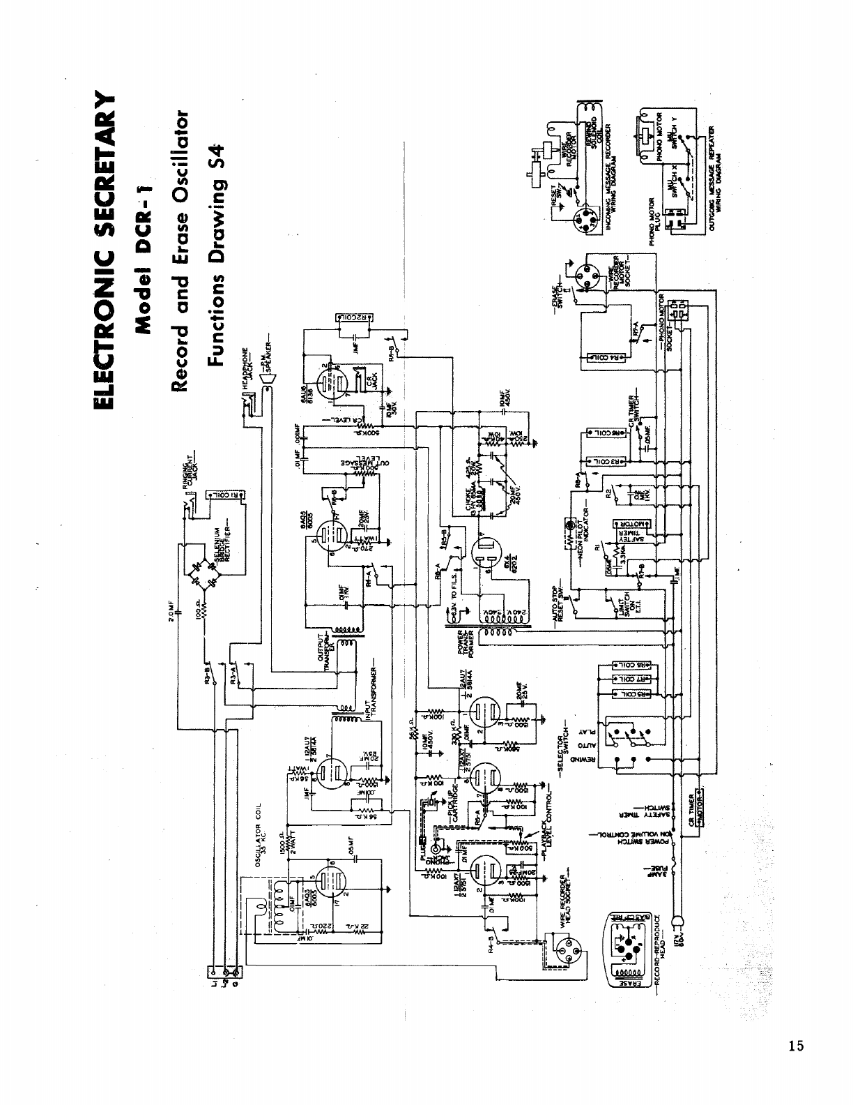
To comprehend fully the conditions of playback,we
can
re-
fer
advantageously to
diagrams
S5
and
S7.
Electronically,
we
see
that
small
voltages
generated
by
passing
magnetically
treated
•
TCI Library www.telephonecollectors.info
......
CJ1
•1111"".
-----
.!
~
-RECORD-REPRODUCE
HEAD-
osc!'i·~t?R
COi
L
''ti
u
2.0MI'
ELECTRONIC
SECRETARY
Model
DCR• 1
Record
and
Erase Oscillator
Functions Drawing
54·
~
a:[)
~
~"•·:
~
~
~
5 • S•
11tt.r
J . 1 ' t
IJ
1
"""""tt;m
~-----
~
TCI Library www.telephonecollectors.info

16
The Playback
Action
Action of
Relay Contact
5a
Relay Contact
6b
Relay Contact
4a
Relay Contact
8b
Relay Contact
3a
Electrical
Operation
Dur-
ing Playback
Function of
Relays
.7,
5,
And 8
Delayed Action
of Wire
Recorder
Rewind
wire
thru
the
slot
in the
recording
head, will be fed through an
,01 condensor into the
first
playback
pre-amplifier
which
is
a
section
of
a
12AX7
tube. Leaving the output
of
this voltage
amplifier
tube, the signal
reaches
the
high
side
of a 500,000 ohm
volume
control,
whose movable
arm
is
now switched into the
grid
circuit
of
the succeeding tube by the action of
relay
contact
5a, which
is
one of the
relay
contacts
affected by placingthe
main
control
switch into
either
the rewind
or
playback
positions.
The
action of 5a
has
now
madethe volume
control
available
as
a
play-
back volume
control
and
it
is
located
for
convenience on
the
front
panel of the machine. The signal continues on through
the
second
section
of the 12AX7 and the 12AU7 and on
to
the junction
point,
where
the
6AQ5
and 6AU6
are
fed.
We
note, however,
that
under
conditions of playback (see
.35)
Relay contact 6b will
be
open,
so
the CR
relay
and tube will be inoperative.
Normally
closed
relay
contact
4a
will, however, be closed. Thus supplying
plate voltage
for
output tube 6AQ5. The playback
signal
will then
proceed
through the now
closed
contact
8b, whose switching action
takes
the full voltage
from
the top connection of the volume
con-
trol
potentiometer
rather
than the
partial
drop
from
the
arm
of
the
control.
The
signal
will then go on through
the
6AQ5
where
it
will
attain
a
very
high
level
of voltage and power and will
transfer
this
energy
through
its
output
transformer,
whose
secondary
will
now
be connected to the voice
coil
of
the
speaker
through the
normally
closed
contact
relay
3a.
To
get
the complete
picture
electrically
ofplayback action,
we
can
refer
to
diagrams
S5
and
S7
).
We
have
thus
far
accounted
for
the action of
relay
contact
5a and
Sb
in the playback
cycle.
We
see
from
the
electrical
portion
of
the
schematic,$7),
that
re-
lays
5, 7, and S
are
involved
in
the playback action. This
leaves
contacts
5b, 7b, and
8a
unexplained.
Studying
adiagram
of
the
power supply S6, we
see
that
con-
tact
5a
provides
a closing of the negative
return
of the
power
supply on playback,
just
as
6a
does
during the automatic
cy-
cle.
Contact 7b in
its
normally
closed
position,
provides
a
path
to
the
trigger
relay
contact
Rl
and the automatic
portion
of the
cir-
cuit
when in the automatic position, but when
relay
7
is
energized
in playback
it
breaks
this
path and
forms
one
to
pin 2
of
the
re-
corder
motor
socket,
which
is
the
wire
recorder
motor
"hot
side".
Relay
contact
7a
breaks
the
path
to
relay
coil
4 when
re-
lay 7
is
energized
thus
allowing the
wire
recorder
motor
to
run
without
relay
4 being
energized.
Relay contact Sa
breaks
the
neutral
to
relays
3 and 6 when
relay
S
is
energized.
To complete
our
electrical
study we
must
learn
how the
CR
motor
device
is
used
iri
the rewind cycle
to
introduce a delay
before
the
wire
recorder
reverses
itself.
The
purpose
of
this
delay
is
to
allow the high
speed
reversal
to
be
initiated
under
motor
conditions of
full
torque and speed. To fully
comprehend
this,
we
must
be cognizant
of
thefundamental
operating
principles
TCI Library www.telephonecollectors.info

....
-.:i
~f:i,.--~~~~~~~~~~-+-.
G~~
~
~
~
-RECORD-REPRODUCE
HEAD-
os'1'&'-~r>R
COIL
.06MF'
u
-SE
I.ECTOR
SWITCH-
!
2.0MF
"e!f-.i_
ILICTRONIC
SECRETARY
lt\oclel DCR-·1
Playback Amplifier Functions
Drawing
SS
C]
-
.--~~~~~~~~~~~~~~~~~~~~~~~~~J
SPEAKER~
.OJMf
lt\\I.
...
"
4;)i
·~
i=---4-----
a
-AlllOSTCP
RESETSW.-
D_
I
rw
81 I
IOlllF
~v.
IHCOlllWl"'li'i~="AMRECOAOER
~:l)
~
1"
~
~ ~
l l
n:rw
~
I
~ ~
1
~
1
ra~
OUTGOllG
lo£SMGE
REPEATER
WIAING
DIAGRAM
TCI Library www.telephonecollectors.info
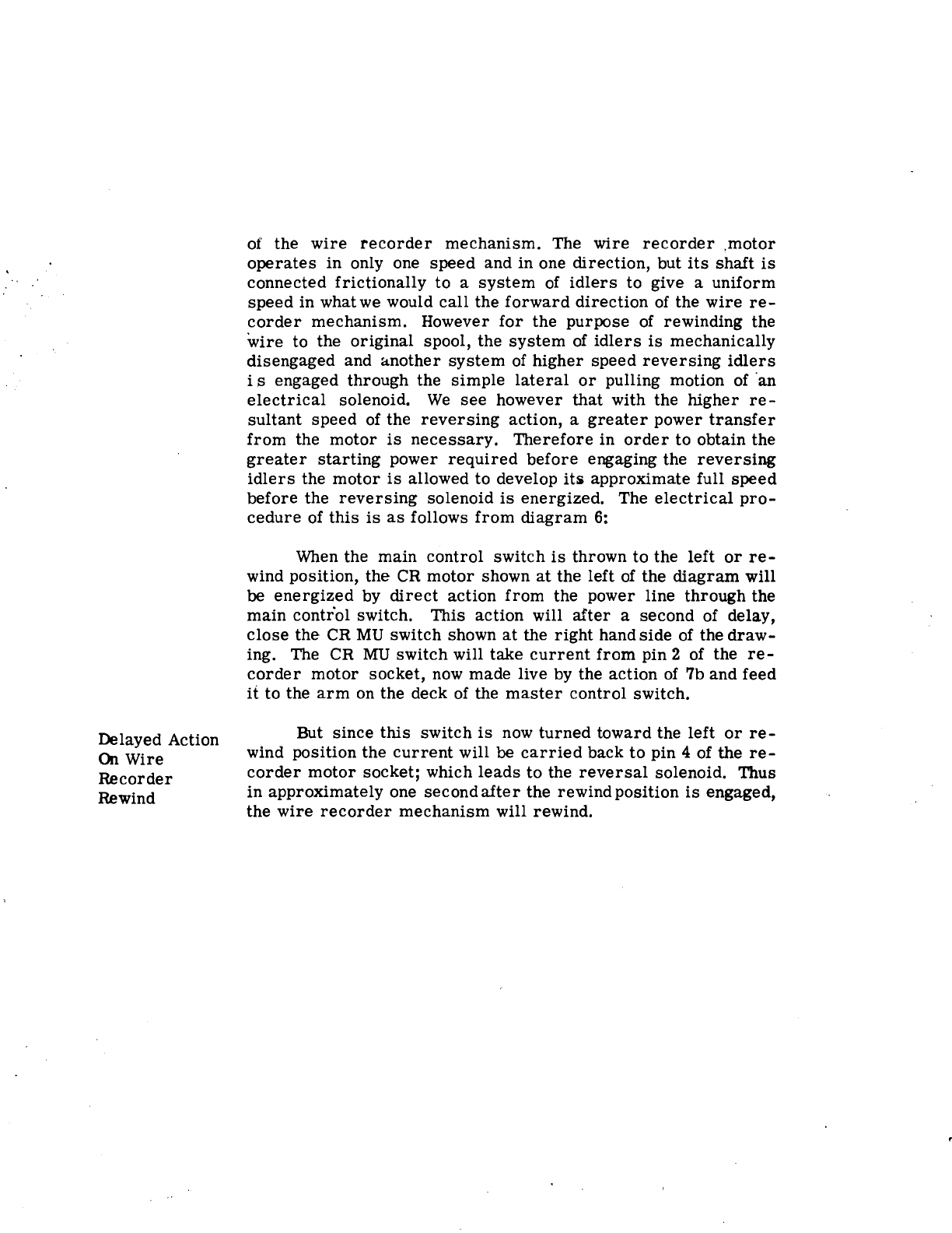
Delayed Action
On Wire
Recorder
Rewind
of the
wire
recorder
mechanism. The wire
recorder
,motor
operates
in only one speed and in one direction, but
its
shaft
is
connected frictionally to a
system
of
idlers
to give a uniform
speed
in whatwe would
call
the
forward
direction
of the
wire
re-
corder
mechanism. However
for
the purpose of rewinding the
wire
to the original spool, the
system
of
idlers
is
mechanically
disengaged and
&.nother
system
of
higher speed
reversing
idlers
i s engaged through the
simple
lateral
or
pulling motion of ·an
electrical
solenoid.
We
see
however that with the higher
re-
sultant speed of the
reversing
action, a
greater
power
transfer
from
the
motor
is
necessary.
Therefore
in
order
to obtain the
greater
starting
power
required
before
engaging the
reversing
idlers
the
motor
is
allowed to develop itli approximate full
speed
before the
reversing
solenoid
is
energized. The
electrical
pro-
cedure
of
this
is
as
follows
from
diagram
6:
When the main control switch
is
thrown
to
the left
or
re-
wind position, the
CR
motor
shown
at
the left of the
diagram
will
be
energized
by
direct
action
from
the power line through the
main
contr"ol switch. This action will
after
a second of delay,
close
the
CR
MU
switch shown
at
the
right
handside of the
draw-
ing. The CR
MU
switch will take
current
from
pin 2 of the
re-
corder
motor
socket,
now
made live by the action of 7b and feed
it
to the
arm
on the deck of the
master
control switch.
But
since
this
switch
is
now
turned
toward the left
or
re-
wind position the
current
will be
carried
back
to
pin 4 of the
re-
corder
motor
socket; which
leads
to the
reversal
solenoid. Thus
in
approximately one
secondafter
the
rewindposition
is
engaged,
the
wire
recorder
mechanism will rewind.
TCI Library www.telephonecollectors.info

,,
.....
co
H~~~=====i
~
-RECORD-REPRODUCE
HEAD-
OSC!!,l{t°R
COIL
..
1
~~
!
0
!!'
:c~
a:
i~
~I
a:~
·§~
~~
~~
-SELECTOR
SWITCH-
!
ELECTRO~\tlC
SEtREr
A:;:.·y
Model
DCR-. 1
2.0MF
Power
Sup"•~y
Drawing
56
100..n.
.________[~
~-------------------------~CJstt~i<ER-
-AUTOSTO?
RESET
SW~
D.
...
"
~
c:--L--~
a
HLI
~I
.I..,~~~
§~
R6-B
.!
tOMF
4.!>0V.
-~
n
~~~~AM
RECORDER
~~=1.r--
---
- -'- -
--
f < T 1 i . .
...
""
~
' <
~
' < i
fli:o~
OUTGOllG
ME:SSMZ
R£1'£ATDI
-NG
DWlAAM
TCI Library www.telephonecollectors.info
Table of contents


