Electronics & Innovation 403LA User manual

Form 080/01
Complimentary Reference Material
This PDF has been made available as a complimentary service for you to assist in
evaluating this model for your testing requirements.
T G offers a wide range of test equipment solutions, from renting short to long
term, buying refurbished and purchasing new. Financing options, such as
Financial Rental, and Leasing are also available on application.
T G will assist if you are unsure whether this model will suit your requirements.
Call T G if you need to organise repair and/or calibrate your unit.
If you click on the “Click-to-Call” logo below, you can all us for FREE!
TMG Corporate Website TMG Products Website
Disclaimer:
All trademarks appearing within this PDF are trademarks of their respective owners.

The material contained in this document is the property of Electronics & Innovation Ltd., it is
subject to change without notice.
February 007 Page 1 of 10 Revision C
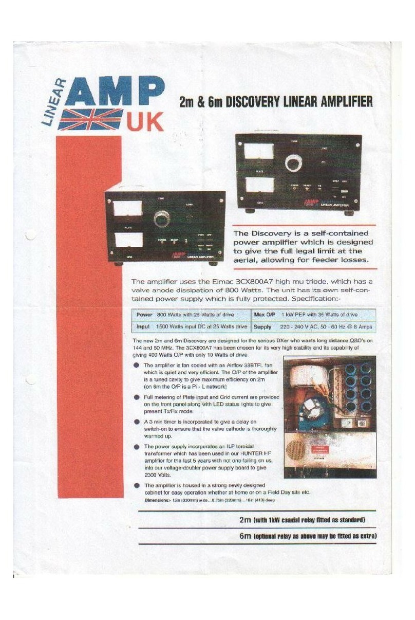
403LA
Broadband Power Amplifier
HIGH RF VOLTAGES MAY BE PRESENT AT THE OUTPUT OF THIS
UNIT. All operating personnel should use extreme caution in handling these
voltages and be thoroughly familiar with this manual.
Do not attempt to operate this unit prior to reading this manual.

The material contained in this document is the property of Electronics & Innovation Ltd., it is
subject to change without notice.
February 007 Page of 10 Revision C
Warranty
Electronics & Innovation Ltd., (hereafter E&I) warrants for the period of one year
from the date of original delivery, each unit to be free of defects in materials and
workmanship. For the period of 1 months E&I will, at its option, repair or replace
defective parts so as to render the unit fully operational such that it performs
according to the original specifications; free of charge to the original purchaser.
Should warranty service be required, the unit must be returned to E&I, freight
cost to be borne by the owner. If, in our opinion, the unit has been damaged by
use outside the limits prescribed in this manual or by accident, then the warranty
shall not be honored. In such a case E&I will provide an estimate for repair,
assuming repair is possible and provide a quote at standard service rates.
Contents
Chapter 1
General Information……………………………………………………………3
Chapter
Operation………………………………………………………………………..4
Chapter 3
Technical Information………………………………………………………….7
Chapter 4
Maintenance……………………………………………………………………8
Chapter 5
Safety……………………………………………………………………………1

The material contained in this document is the property of Electronics & Innovation Ltd., it is
subject to change without notice.
February 007 Page 3 of 10 Revision C
Chapter 1 Introduction
The Model 403LA is a general purpose broadband amplifier capable of more
than 3W of linear power output when driven by any laboratory signal or sweep
generator from 0.15 to 300 MHz
An ultra linear Class A design, the 403LA will "boost" the output of any signal
source by at least a flat 37 dB (±1 dB) and provide its full forward output power
into any load impedance (from an open to a short circuit). Its output is a faithful
reproduction of the input waveform for AM, FM, SSB, CATV, pulse and other
complex modulations. Although specified only over the 0.15 to 300 MHz
frequency range, full power output is typically available from 0.1 to 3 0 MHz.
The use of RF DMoS transistors with microstrip circuitry ensures that the 403LA
is both a reliable and rugged source of RF power. An integral power supply and
cooling system permit operation over a wide range of temperature and AC line
conditions.
1 2 INSTRUMENTATION IDENTIFICATION
Each amplifier is identified by a serial number tag on the back panel of the unit.
Both the model number and the serial number should be quoted to identify a
specific unit. As shown below:

The material contained in this document is the property of Electronics & Innovation Ltd., it is
subject to change without notice.
February 007 Page 4 of 10 Revision C
1 3 SPECIFICATIONS
Physical and electrical specifications are listed in Table 1 below:
Frequency Coverage 0.15 – 300 MHz
Gain 37 dB nominal
Gain Variation +/- 1 dB
Maximum Power Output 3 Watts (min)
Harmonic Distortion - 5 dBc @ .7 Watts Pout
Input / Output Impedance 50 Ω
Input VSWR 1.5 Maximum
Output VSWR .5 Maximum
Stability Unconditionally stable into all passive
loads
IOP
3
Typical 44.5 dBm
Noise Figure 9 dB
Power Requirement 115/ 30 VAC +/-10% 50–60 Hz, 45 W.
Max
3.4 x 6. x 10.5 inches, 7 lbs
Size and Weight 8.8 x 15.7 x 6.6 cm, 3. Kg
Operating Temperature 0
0
to 45
0
C.
Protection Units will withstand 0 dB overdrive
Output Connectors BNC, Standard, SMA and N-type
optional
Rack Mounting Adaptors provided
Chapter 2 Operation
2 1 INTRODUCTION
The E&I 403LA RF amplifier is used to increase the RF output level of signal
sources in the 0.15 to 300 MHz range. No tuning or any other form of adjustment
is required.
The 403LA produces rated power output at its output connector, regardless of
load impedance. Any power reflected due to output load mismatch is absorbed in
the amplifier. Therefore, although the output impedance is 50 Ω (typical RF
Output VSWR: :1), the amplifier will work into any load impedance.

The material contained in this document is the property of Electronics & Innovation Ltd., it is
subject to change without notice.
February 007 Page 5 of 10 Revision C
2 2 Rack Installation
For standard 19" rack installations, rack mounting brackets are supplied with the
unit. Remove the two M4 Phillips screws on each side of the cover nearest the
front panel. Either bracket may be used on the right or left side. Attach the rack
mounting brackets firmly using the hardware removed above. The rubber feet
may be unscrewed and removed if the minimum vertical usage of the relay rack
is necessary.
2 3 Mains Voltage
The supply voltage is automatically selected from 85 TO 64 VAC 47 – 63 Hz
2 4 Mains Fuse Rating
The mains fuse Fl is located on the rear panel. The replacement part number
details are:
1A Slow Blow E&I Part No: F975-ND. The 1A rating is correct for both 115
and 30 VAC
2 5 Mains Lead Connection
The unit comes supplied with a 6 foot mains cord.
2 6 Operation
Proceed as follows:
• Ensure input voltage is not excessive
• The IV RMS indicated maximum input voltage is 5 times the level of
the input signal required to achieve maximum output. Input voltages
in excess of V peak may permanently damage the instrument.
• Connect the input signal via a 50Ω coaxial lead and BNC plug to
the input connector.
• Connect the output via a 50 Ω coaxial lead and BNC plug to the
load.

The material contained in this document is the property of Electronics & Innovation Ltd., it is
subject to change without notice.
February 007 Page 6 of 10 Revision C
Chapter 3 Technical Information
3 1 Performance Checks
To determine the amplifier's performance carry out the following procedure.
3.1.1 Initial Check
The following check can be made whenever the condition of the unit is in
question.
(i) Connect power supply. Switch on power and observe that the switch
illuminates.
(ii) Connect the output of the 403LA amplifier to 0 dB attenuator.
(iii) Connect a calorimetric power meter (HP434 or equivalent) to the output of
the attenuator.
(iv) Connect a sweep generator (Wavetek 001 or similar) capable of
sweeping the frequency range 1 to 300MHz to the input connector, ensure
that the output power of the generator is initially set to minimum.
(v) Adjust the output level of the sweep generator to -10dBm.
(vi) Adjust the input CW signal to any frequency between 1 and 300MHz for
3W output.
If you can not attain RF power, verify that:
(a) The mains fuse is correctly selected and not blown
(b) The switch is illuminated.
If the mains fuse is not blown but you are still unable to get any RF power, either
return the unit to E&I for repair or proceed to chapter 4.
3 2 Measurement of Gain
Equipment required:
(a) Two power meters; HP 434 or equivalent
(b) Sweep/Signal Generator
(c) 0 dB Coupler

The material contained in this document is the property of Electronics & Innovation Ltd., it is
subject to change without notice.
February 007 Page 7 of 10 Revision C
(d) Attenuator, 0 dB
Connect the equipment as shown in Figure , then proceed as follows:
(a) Increase power from the signal generator to attain an output
power measurement of 3 watts as indicated on the output power
meter.
(b) Measure input power and calculate gain. Gain should be a
nominal 37 dB
(c) Vary the frequency of the sweep generator across the band
from 150 KHz to 300 MHz. Note that the variation of gain is
within +/- 1.5 dB
3 3 Measurement of Harmonics
Equipment required:
(a) Sweep/Signal generator
(b) Attenuator, 0 dB
(c) Power Meter - HP434A
(d) Spectrum Analyzer
Connect the equipment as shown in Figure 3 then proceed as follows:
(d) Adjust the sweep/Signal generator at a CW center frequency of
150 MHz for an indicated output of .7W on the power meter.
(e) Using the spectrum analyzer, check that the level of harmonics
are less than - 5 dB with respect to the carrier.
(f) Vary the frequency of the generator from 150 KHz to 300 MHz,
the harmonics should remain at - 5dBc or below.
Chapter 4 Maintenance
4 1 Introduction
The E&I 403LA RF amplifier requires no periodic maintenance. The instrument is
unconditionally stable and is fail safe under all load conditions. Damages can
only be externally caused by an input signal in excess of the specified IV RMS
maximum.

The material contained in this document is the property of Electronics & Innovation Ltd., it is
subject to change without notice.
February 007 Page 8 of 10 Revision C
This chapter therefore, deals only with certain fundamental procedures for fault
location and with the subsequent re-alignment procedures.
Performance limits quoted are for guidance only and should not be taken for
guaranteed performance specifications unless they are also quoted in Figure 1.
4 2 Packing for Reshipment
In the event of the equipment being returned for servicing it should be packaged
in the original shipping carton and packing material. If this is not available wrap
the instrument in heavy paper or plastic and place in a rigid outer box of wood,
fiberboard or very strong corrugated cardboard. Use ample soft packing to
prevent movement. Provide additional support for projecting parts to relieve
these of unnecessary shock. Close the carton securely and seal with durable
tape. Mark the shipping container FRAGILE to ensure careful handling.
4 3 Access and Layout
NB: Removal of the cover voids the warranty!
The E&I Model 403LA amplifier is housed in an aluminum chassis. A block
diagram schematic is illustrated in figure 4. The cover can be removed by
releasing the 6 M3 screws on the side of the unit.
The rear panel supports the mains fuse holder, AC line cord and the cooling fan.
4 4 Power supply
The power supply does have a separate fuse. This fuse is rated at .5 amps /
50 Volts. It can be accessed without further disassembly. The power supply is
mounted vertically on the left hand side of the amplifier. The fuse is located to the
rear of the unit as indicated below.

The material contained in this document is the property of Electronics & Innovation Ltd., it is
subject to change without notice.
February 007 Page 9 of 10 Revision C
4 5 The Amplifier Module
The power amplifier module is mounted on the RF heat sink. To remove this
module, the RF heat sink must be demounted from the chassis. To demount the
heat sink, unplug the wire from the power supply module. Remove the coaxial
cables connecting the RF input and output to the front panel connectors. Remove
the two M4 nuts holding the heat sink to the chassis base and the M3 phillips
screws holding the heatsink to the chassis side, then lift straight up.
Chapter 5 Safety:
Do not attempt to operate this unit with the cover removed. High AC and DC
voltages are present. The cover prevents against electrical shock due to AC line
voltages, high DC and RF fields. Further the cover provides part of the cooling
system design. Components, specifically on the RF driver board are prone to
over-heat and eventual failure if the unit is operated without the cover in place.
Ensure that the load is connected to the output prior to connecting the RF input
to the unit. This will prevent high voltages being present and exposed at the
output connector.
Only use the AC cord provided or equivalent.
Ensure that the mains outlet is properly grounded.
Figure 1
Gain Measurement
Power Meter
Sweep Generator
RF Output
150 KHz – 300
0 dB
Atten
uator
Power Meter

The material contained in this document is the property of Electronics & Innovation Ltd., it is
subject to change without notice.
February 007 Page 10 of 10 Revision C
Figure 2
Harmonic Measurement
Figure 3
Block Diagram
Power Meter
Sweep Generator
RF Output
150 KHz
–
300 MHz
0 dB
Attenuator
Spectrum Analyzer
Other Electronics & Innovation Amplifier manuals
Electronics & Innovation
Electronics & Innovation 500S06 User manual
Electronics & Innovation
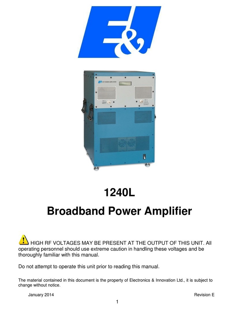
Electronics & Innovation 1240L User manual

Electronics & Innovation
Electronics & Innovation 601L User manual

Electronics & Innovation
Electronics & Innovation 411LA User manual
Electronics & Innovation
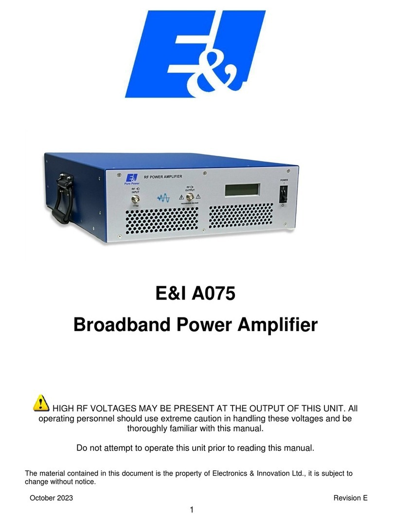
Electronics & Innovation A075 User manual
Electronics & Innovation
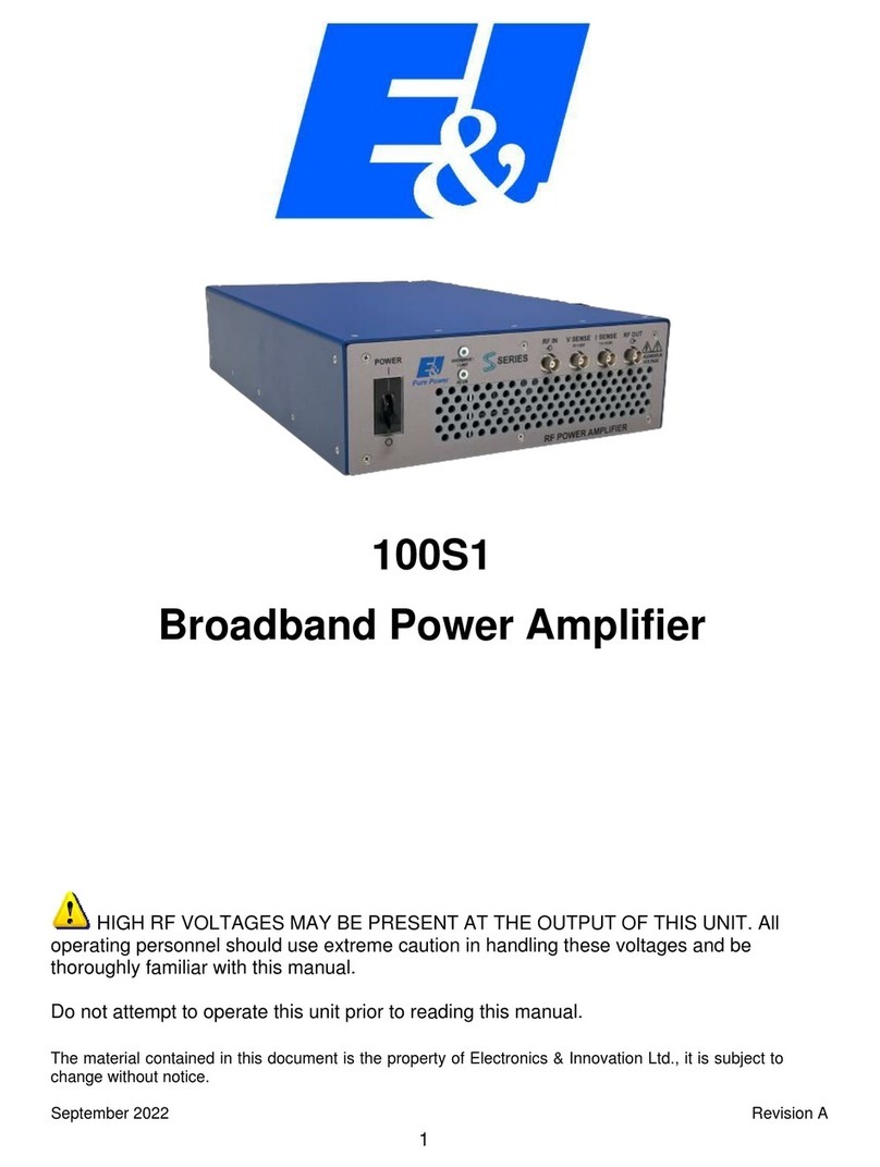
Electronics & Innovation 100S1 User manual
