Electronics & Innovation 100S1 User manual

The material contained in this document is the property of Electronics & Innovation Ltd., it is subject to
change without notice.
September 2022 Revision A
1
100S1
Broadband Power Amplifier
HIGH RF VOLTAGES MAY BE PRESENT AT THE OUTPUT OF THIS UNIT. All
operating personnel should use extreme caution in handling these voltages and be
thoroughly familiar with this manual.
Do not attempt to operate this unit prior to reading this manual.

The material contained in this document is the property of Electronics & Innovation Ltd., it is subject to
change without notice.
September 2022 Revision A
2
Warranty
Electronics & Innovation Ltd., (hereafter E&I) warrants for the period of three years from
the date of original delivery, each unit to be free of defects in materials and workmanship.
For the period of 36 months E&I will, at its option, repair or replace defective parts so as to
render the unit fully operational such that it performs according to the original specifications;
free of charge to the original purchaser.
Should warranty service be required, the unit must be returned to E&I, freight cost to be
borne by the owner. If, in our opinion, the unit has been damaged by use outside the limits
prescribed in this manual or by accident, then the warranty shall not be honored. In such a
case E&I will provide an estimate for repair, assuming repair is possible and provide a
quote at standard service rates.
Contents
Chapter 1
General Information……………………………………………………………3
Chapter 2
Operation………………………………………………………………………..4
Chapter 3
Technical Information………………………………………………………….7
Chapter 4
Maintenance……………………………………………………………………8
Chapter 5
Safety……………………………………………………………………………12

The material contained in this document is the property of Electronics & Innovation Ltd., it is subject to
change without notice.
September 2022 Revision A
3
Chapter 1 Introduction
The 100S1 is a broadband solid state amplifier covering the frequency spectrum from 20
to 1 MHz. It is rated at 100 watts of RF power with low harmonic and intermodulation
distortion. A Class D design, the 100S1 will amplify inputs of AM, FM, SSB, pulse and any
complex modulation signals within the bandwidth of the amplifier. The amplifier has 50 dB
gain, it is unconditionally stable and will not oscillate even with combinations of mismatched
source and load impedance. It is protected against failure due to output load mismatch
and/or overdrive.
1.2 INSTRUMENTATION IDENTIFICATION
Each amplifier is identified by a serial number tag on the back panel of the unit. Both the
model number and the serial number should be quoted to identify specific unit.
1.3 SPECIFICATIONS
Physical and electrical specifications are listed in Table 1-1 below

The material contained in this document is the property of Electronics & Innovation Ltd., it is
subject to change without notice.
September 2022 4 Revision A
Table 1-1. SPECIFICATIONS
FREQUENCY COVERAGE:
20 to 1000 KHz
GAIN:
50 dB min, ±1.0 variation.
CLASS D LINEAR OUTPUT:
Nominal 100 watts.
INPUT IMPEDANCE
50 ohms, VSWR, 1.5:1 Maximum.
OUTPUT IMPEDANCE:
50 ohms, VSWR, 2.5:1 Maximum
STs STABILITY:
Continuous operation into any load or
source impedance.
DRIVE LEVEL FOR 100 W
0 dBm or 0.22 Vrms
PROTECTION:
Unit will withstand a + 24 dBm input
signal, without damage.
POWER REQUIREMENTS:
110 –240 VAC
50 / 60 Hz
SIZE:
3 1/4 X 10 X 15 inches 8.27 X 25.4 x
38.1 cm.
WEIGHT:
15 pounds 6.8 kg
CONNECTORS:
BNC (power) BNC (sample ports)
OPERATING TEMPERATURE:
0 –40 C
RACK MOUNTING:
2 U Chassis
Chapter 2 Operation
2.1 INTRODUCTION
The 100S1 RF amplifier is used to amplify the RF level of signal sources in the 20
to 1 MHz. No tuning or any other form of adjustment is required.
The 100S1 produces rated power output at its output connector into 50 Ohms. It
will produce less power at other load impedances. Therefore, although the output
impedance is 50 ohms, the amplifier will work into any load impedance.
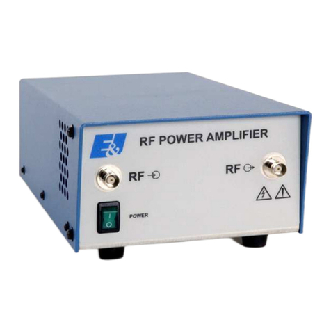
On the front of the unit there are BNC connectors for current and voltage monitors.
These monitors provide a scaled down representation of the output waveform.
Scaling:
Voltage monitor into 50 Ohms 1V = 50 V at amplifier output
Current monitor into 50 Ohms 1V = 0.5 A at amplifier output

The material contained in this document is the property of Electronics & Innovation Ltd., it is
subject to change without notice.
September 2022 5 Revision A
Note: Signal processing of these monitors can provide information such as VSWR,
load impedance, phase etc., as the phase relationship between V and A is
maintained.
2.2 RACK INSTALLATION
This unit is 2U high.
2.2.1 Input Voltage
The unit requires 110 –240 VAC 50/60 Hz
2.3 OPERATION
The AC input is an IEC 60320 C20 receptacle. A line cord is supplied to provide a
connection between the supply and the rear of the unit.
2.3.1 Proceed as follows:
(i) Ensure that there is at least 3” or 7.5 cm clearance at the rear of the unit
for air flow.
(ii) Connect the output via a 50 ohm coaxial lead and N connector to the
load.
(iii) Connect the AC supply to the rear of the unit.
(iv) Connect the input signal via a 50 ohm coaxial lead and N connector to
the input connector.
Chapter 3 Technical Description
3.1 GENERAL DESCRIPTION
The 100S1 is designed to amplify signals by 50 dB in the frequency band of 20 to
1 MHz. The signal from the front panel RF connector is fed into the input of the
pre-amplifier module. The pre-amplifier provides voltage gain and signal
conditioning to prevent overdrive of the pulse width modulators. The signal from
the output of the pre-amplifier is fed into the pulse width modulators (PWM) that
are fed from the outputs of the oscillator and ramp generator. The output of the
bridge is then fed through the low pass filter network to recover the signal
waveform; then fed to the N connector at the output.

The material contained in this document is the property of Electronics & Innovation Ltd., it is
subject to change without notice.
September 2022 6 Revision A
There is a current limit protection circuit to protect the unit, in addition to the input
drive clamp. Current and voltage samples are taken from the output and fed to the
BNC connectors on the front panel for monitoring purposes.
The AC supply is fed through an EMI filter to the power supply that converts the
AC to 53 Vdc for the amplifier and for the cooling fan and additional DC-DC
converters to supply the floating + 15 V for the gate drivers and +/- 15 volt rails,
for the control circuitry.

The material contained in this document is the property of Electronics & Innovation Ltd., it is
subject to change without notice.
September 2022 7 Revision A
Chapter 4 Maintenance
4.1 INTRODUCTION
The E&I 100S1 RF amplifier requires no periodic maintenance. The instrument is
unconditionally stable and is fail-safe under all load conditions. Damage can only
be externally caused by overdrive in excess of 2 watts (+33 dBm) or back-feeding
the output of the unit from another high power source or incorrect connection to
the AC input.
4.2 PACKAGING FOR RESHIPMENT
In the event of the equipment being returned for servicing it should be packed in
the original shipping carton and packing material. If this is not available, wrap the
instrument in heavy paper or plastic and place in a rigid outer box of wood,
fiberboard or very strong corrugated cardboard. Use ample soft packing to prevent
movement. Provide additional support for projecting parts to relieve these of
unnecessary shock. Close the carton securely and seal with durable tape. Mark
the shipping container FRAGILE to ensure careful handling.
Chapter 5 Safety:
Do not attempt to operate this unit with the cover removed. High voltages are
present. The cover protects against electrical shock due to hazardous supply
voltages, high DC, RF voltages and RF fields. Further the cover provides part of
the cooling system design. Components will over heat and cause eventual failure
if the unit is operated without the cover in place.
N.B. Removal of cover will void warranty.
Ensure that the load is connected to the output prior to connecting the RF input to
the unit. This will prevent high voltages being present and exposed at the output
connector.
Operation of AC voltage above 264 V could severely damage the unit and present
a hazard.

The material contained in this document is the property of Electronics & Innovation Ltd., it is
subject to change without notice.
September 2022 8 Revision A
Table of contents
Other Electronics & Innovation Amplifier manuals

Electronics & Innovation
Electronics & Innovation 411LA User manual
Electronics & Innovation
Electronics & Innovation A075 User manual
Electronics & Innovation
Electronics & Innovation 500S06 User manual

Electronics & Innovation
Electronics & Innovation 601L User manual
Electronics & Innovation
Electronics & Innovation 1240L User manual
Electronics & Innovation
Electronics & Innovation 403LA User manual

