Elenberg MX-390DVD User manual

Car Audio
Page
TABLE OF CONTENTS
Technical Specifications ....................................................1-2
Measurement setup ..........................................................1-3
Service Aids, Safety Instruction, etc .......................... 1-4 to 1-5
Preparations & Controls............................................ 1-6 to1-8
Maintenance & Troubleshooting ....................................... 1-9
Disassembly Instructions & Service positions ........................ 2
Set Block diagram ............................................................... 3
Set Wiring diagram .............................................................. 4
Key Board ........................................................................... 5
Servo Board ........................................................................ 6
Main Board ......................................................................... 7
Set Mechanical Exploded view & parts list .............................. 8
MX-390DVD
U
N
E
P
R
U
G
N
R
K
E
T
D

SPECIFICATIONS
1-2
General
Power supply:
Maximum power output:
Suitable speaker impedance:
Pre-Amp output voltage:
12V DC(11V-16V)
Test voltage 14.4V, negative ground
45Wx4 channels
4-8 ohm
Fuse:
Dimensions(WxHxD)
Weight:
15A
178x50x155mm
1.7kg
2.0V
Components
Mountingcollar
Tappingscrews M5x6 mm 4
M4x6 mm 4
Mountingbolt (50 mm) 1
Wireconnector
Trimplate 1
T-key 2
1
Rubber cushion 1
1
1
1
User manual
Removable face plate case
Note: Specifications and design are subject to change
without notice for product improvements.
Continuous power output: 20Wx4 channels (4 10% T.H.D.)
Remote control 1
Disc Player
System:
Frequency response:
Signal/noise ratio:
Total harmonic distortion:
Channel separation:
Disc digital audio system
20 Hz - 20KHz
>80 dB
Less than 0.20%(1KHz)
>60 dB
FM Stereo Radio
Frequency range:
Sensitivity:
Frequency response:
Stereo separation:
Image response ratio:
IF response ratio:
Signal/noise ratio
8 dB
30Hz-15KHz
30dB(1KHz)
50dB
70dB
55dB
87.5 - 108.0 MHz
65.0-74.0 MHz (OIRT mode)
Video:
video output:
horizontal nesowtiou:
1 0.2V
500 lines
Video signal format system: PAL/NTSC
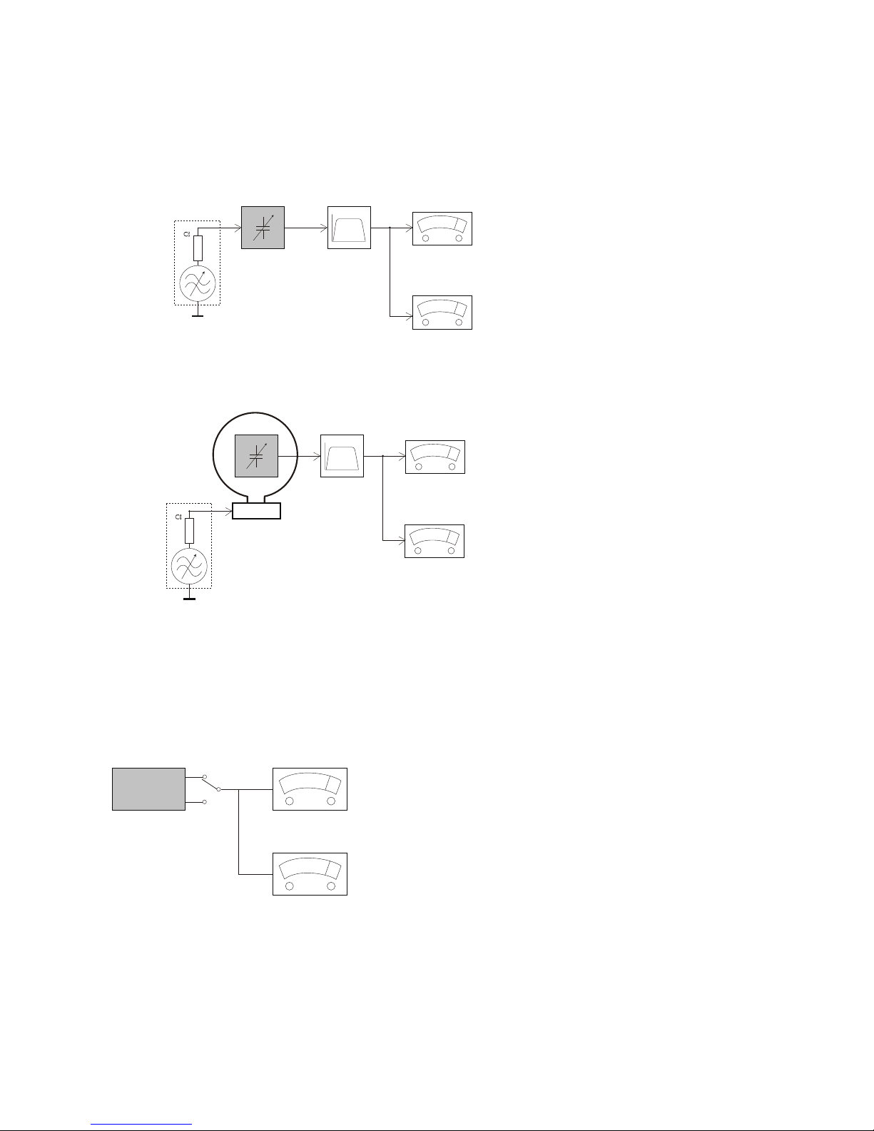
MEASUREMENT SETUP
Tuner FM
DUT
RF Generator
Bandpass
LF Voltmeter
e.g. PM5326
250Hz-15kHz
e.g. 7122 707 48001 e.g. PM2534
S/N and distortionmeter
e.g. Sound Technology ST1700B
Ri=50
Use a bandpass filter to eliminatehum(50Hz,100Hz) and disturbance from the pilottone(19kHz,38kHz).
Tuner AM(MW,LW)
DUT
RF Generator
Bandpass
LF Voltmeter
e.g. PM5326
250Hz-15kHz
e.g. 7122 707 48001 e.g. PM2534
S/N and distortionmeter
e.g. Sound Technology ST1700B
Ri=50
Frame aerial
e.g. 7122 707 89001
Toavoid atmospheric interference all AM-measurements have to becarried out in a Faraday s cage.
Use a bandpassfilter ( or at least a high pass filterwith 250Hz) to eliminate hum ( 50Hz,100Hz ).
'
DUT
L
R
LEVEL METER
e.g. Sennheiser UPM550
with FF-filter
S/N and distortionmeter
e.g. Sound Technology ST1700B
Use AudioSignal Disc SBC4294822 397 30184
(replaces test disc3)
CD
1-3
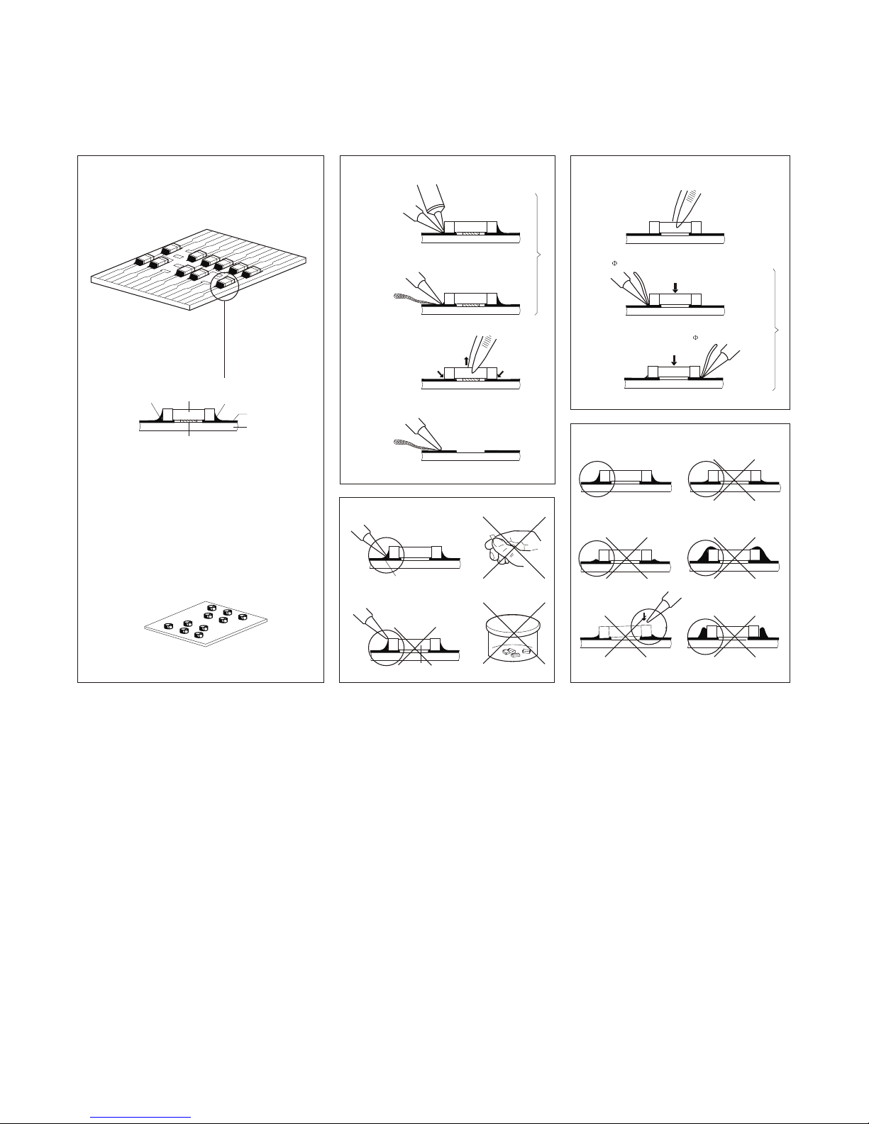
1-4
SOLDER
CHIP
COMPONENT
GLUE
SOLDER
COPPER TRACK
P.C.B
SERVICE PACKAGE
GENERAL DISMOUNTING MOUNTING
SOLDERING
IRON
VACUUM PISTON
4822 395 10082
e.g.WELLER
Solder tip PT-H7
SOLDERING
IRON
SOLDER WICK
4822 321 40042
e.g. A PAIR OF TWEEZERS
HEATING HEATING
SOLDERING
IRON
SOLDER WICK
CLEANING
PRECAUTIONS
COPPER TRACK
IRON
CORRECT
SOLDERING
IRON
SOLDERING
CHIP COMPONENT
EXAMPLES
CORRECT
IRON
SOLDERING
NO
e.g. A PAIR OF TWEEZERS
SLODERING
IRON
SLODER
SLODERING TIME
SLODERING
IRON
0.5-0.8mm
< 3 secretary / side
PRESSURE
PRESSURE
SOLDER
0.5-0.8mm
A
B
C
B
A
HANDLING CHIP COMPONENTS

WARNING
GB
All ICs and manyother semi-conductors are
susceptible to electrostatic discharges(ESD).
Careless handling during repaircan reduce life
drastically.
When repairing, make surethat you are
connected with the samepotential as the mass
of the setvia a wrist wrap with resistance.
Keep components andtools also at this
potential.
CLASS 1
LASER PRODUCT
ATTENTION
GB
Safety regulations requirethat the set be restored to its original
condition and thatparts which are identical with thosespecified,
be used.
1-5
ATTENTION
Tousles IC et beaucoup d'autres
semi-conducteurs sont sensiblesaux
decharges statiques(ESD).
Leur longevite pourraitetre considerablement
ecourtee par le faitqu'aucune precaution n'est
prise a leurmanipulation.
Lors de reparations,s'assurerde bien etre relie
au meme potentielque la masse de l'appareil et
enfiler le braceletserti d'une resistance de
securite.
Veiller ace que les composants ainsi queles
outils que l'on utilisesoient egalement ace
potentiel.
WARNING
D
Alle ICs undviele andere Halbleiter sind
empfindich gegenuber elektrostatischen
Entladungen(ESD).
Unsorgfaltige Behandlung imReparaturfall kan
die Lebensdauer drastischreduzieren.
Veranlassen Sie,dassSie im Reparaturfall uber
ein Pulsarmband mitWiderstand verbunden
sind mit dem gleichenPotential wie die Masse
des Gerates.
Bauteile und Hilfsmittelauch auf dieses gleiche
Potential halten.
F
ESD NL
I
WAARSCHUWING
Alle IC's envele andere halfgeleiders zijn
gevoelig voor electrostatischeontladingen
(ESD).
Onzorgvuldig behandelen tijdensreparatie kan
de levensduur drastischdoen verminderen.
Zorg ervoor datu tijdens reparatie via een
polsband met weerstandverbonden bent met
hetzelfde potentiaal alsde massa van het
apparaat .
Houd componenten enhulpmiddelen ook op
ditzelfde potentiaal.
AVVERTIMENTO
Tutti IC eparecchi semi-conduttori sono
sensibili alle scariche statiche(ESD).
La loro longevita potrebbeessere fortemente
ridatta in casodi non osservazione della piu
grande cauzione allaloro manipolazione.
Durante le riparazioni occorrequindi essere
collegato allo stessopotenziale che quello della
massa dell'apparecchio tramite unbraccialetto
a resistenza.
Assicurarsi che icomponenti e anche gli utensili
con quali si lavorasiano anche a questo
potenziale.
Pour votre securite,ces documents
doivent etre utilisespar des specia-
listes agrees,seuls habilitesa reparer
votre appareil enpanne .
NL
F
D
I
DK
SF
S
GB
Veiligheidsbepalingen vereisen,dathet apparaat bij reparatie in
zijn oorspronkelijke toestandwordt teruggebracht en dat onderdelen,
identiek aan de gespecificeerde,wordentoegepast.
After servicingand before returning set to customer perform a
leakage current measurementtest from allexposed metal parts to
earth ground toassure no shock hazard exist .The leakage current
must not exceed0.5mA.
Le norme di sicurezzaesigono che I'apparecchio vengarimesso
nelle condizioni originalie che siano utilizzati i pezzidi ricambio
identici a quellispecificati.
Warning!
Varning!
Varoitus!
Advarse!
Invisible laser radiationwhen open.
Avoid direct exposureto beam.
3122 110 03420
Avatussa laitteessa jasuojalukituksen ohitettaessa oletalttiina
nakymattomalle laserisateilylle.Ala katso sateeseen!
Usynlig laserstr ling ved abningnar sikkerhedsafbrydere er
ude af funktion.Undgaudsaettelse for straling.
a
Bei jeder Reparatur sinddie geltenden Sicherheitsvorschriften zu
beachten.Der Original zustanddes Gerats darf nicht verandert werden;
fur Reparaturen sindOriginal-Ersatzteile zu verwenden.
Les normes desecurite exigent que I'appareil soit remisa I' etat
d'origine et quesoient utilisees les pieces de rechangeidentiques
a celles specifiees.
Osynlig laserstralning narapparaten ar oppnad och sparren
ar urkopplad. Betraktaej stralen.

PREPARATIONS
Wiring Diagram
1-6
ANT or AMP controll/blue
Battery 12V(+)/yellow
Ground/black
ACC+/red
Filter Box
Ground Lead
Left Speaker
(Front)
Left Speaker
(Rear)
Right Speaker
(Front)
Right Speaker
(Rear)
White/
Black
Stripe
White
Gray/
Black
Stripe
Green/
Black
Stripe
Gray GreenPurple/
Black
Stripe
Purple
B
A
Black
Blue Motor/Electric Antenna relay control Lead
Amplifier relay control Lead
ISO Connector
Connector
Original wiring
Modified wiring
Red
Yellow Yellow
Red
Red
Yellow Yellow
Red
Antenna
Fuse 15A
R(Red)
L(White)
(Yellow)
Line-out (Gray)
Amplifier
For some VW/Audi or Opel(Vauxhall)
car models, you may need to modify
wiring of the supplied power cord as
illustrated, or else the memory of the
unit may be lost after you power off.
Contact your authorized car dealer
before installing this unit.
Ignition key
+12V DC When ON/ACC
To car battery(+)
Continuous +12VDC
Yellow
Red
Video-out
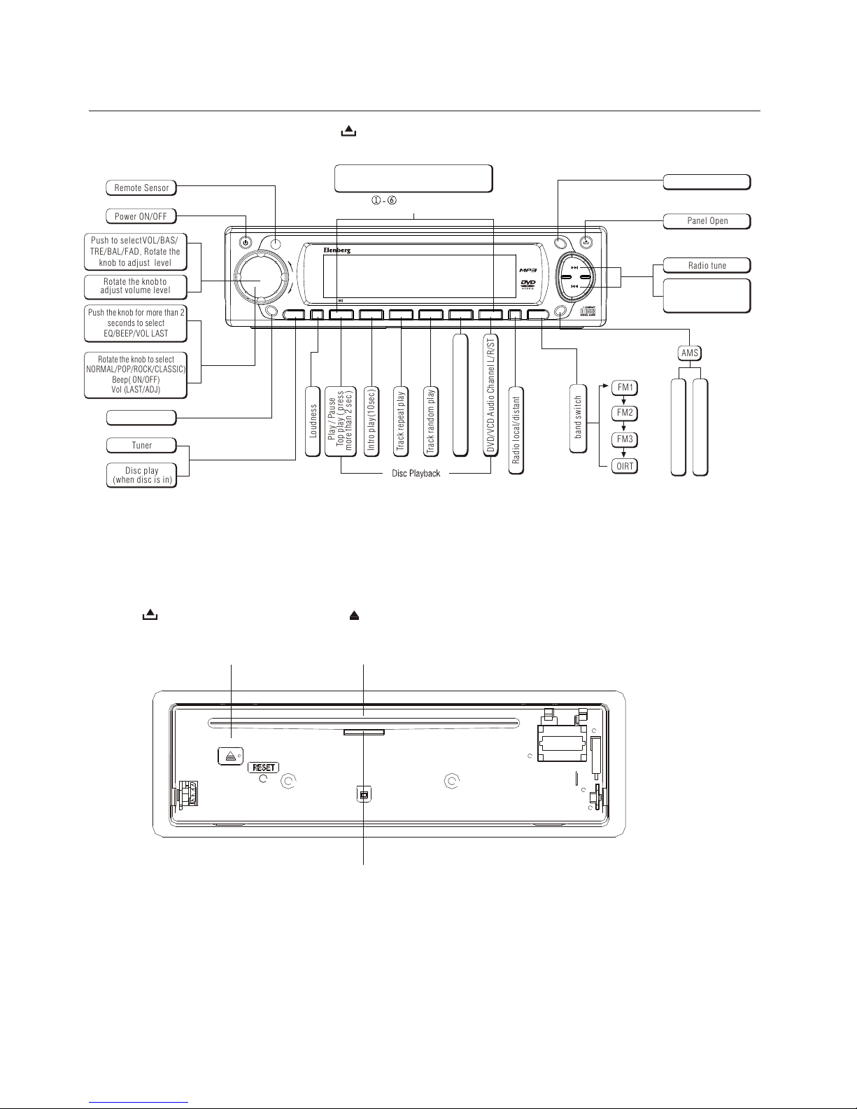
1-7
Power On : Press any button on the panel except to turn on the unit.
CONTROLS
Press the button to open the panel and press to eject the disc.
Disc Eject Slot ,Insert the disc
Panel status indication:
When the panel slide down it will light up.
When the panel detached from body it will flash.
Radio preset
Press to a preset station
Hold for more than2 seconds to storestation
listen to
Panel Open
Play / Pause
Top play ( press
more than 2 sec ).
s
Track random play
Track repeat play
Intro play(10sec)
Power ON/OFF
OIRT
FM1
FM2
FM3
Radio preset scan
Radio auto preset
AMS
Tuner
Disc play
(when disc is in)
band switch
Radio tune
INT RPT RDM
4X45W
PUSH SEL/MENU
VOL-
VOL+
MON
SRC
LOUD
1 2 3 4 5 6
LO/DX
BAND
DSP
AMS
Radio local/distant
Display switch
MENU
IR
CAR DVD PLAYER MX-390DVD
Remote Sensor
FM stereo/mono
To fastsearch within
a track/ skip tonext
or previous track
Loudness
P/N R/L
Video System PAL / NTSC
DVD/VCD Audio Channel L/R/ST
Push the knob for more than 2
seconds to select
EQ/BEEP/VOL LAST
Rotate the knob to select
NORMAL/POP/ROCK/CLASSIC)
Beep( ON/OFF)
Vol (LAST/ADJ)
Rotate the knobto
adjust volume level
Push to selectVOL/BAS/
TRE/BAL/FAD, Rotate the
knob to adjust level
Vol Knob
2nd function
1-8
2. Insert the button-type lithium battery with the
mark facing upward.
(+)
Insert the batteryholder into the
remote control.
1. Pull outthe battery holder while pressing the stopper.
Replacing the lithium battery of remote control unit.
* When theoperation range ofthe card
remote
control becomes shortor no Properly, replace
the lithium batterywith a newone. Make sure
the battery polarityreplacement is correct.
(CR 2025)
WARNINGS:
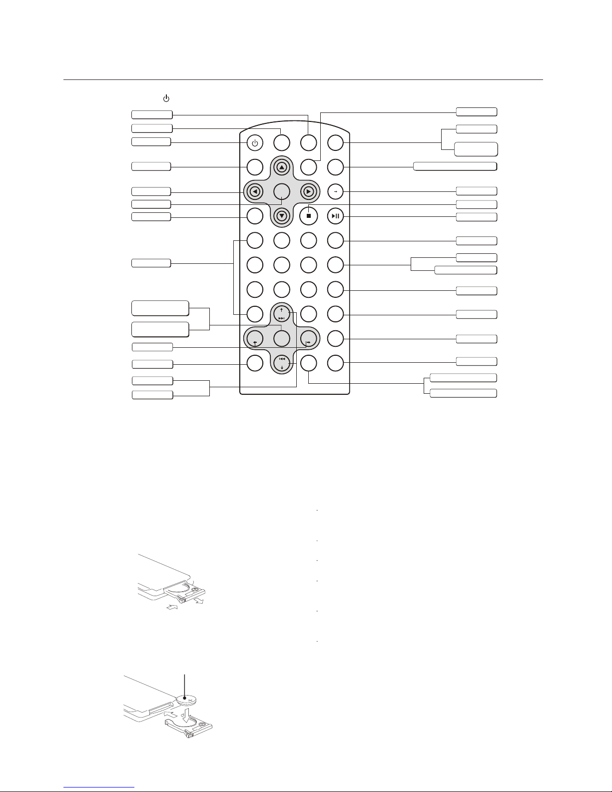
REMOTE CONTROLS
Store the batteryin place wherechildren cannot reach.
If a childaccidentally swallows thebattery,
consult a doctorimmediately.
Do not recharge,short, disassemble orheat the battery
or dispose itin a fire.
Doing any ofthese things maycause the batteryto give
off heat,crack or start a fire.
Do not leavethe battery withother metallic materials.
Doing this maycause the batteryto give off heat, crack
or start afire.
When throwing awayor saving thebattery, wrap it in tape
and insulate;otherwise, thebattery may startto give off
heat, crack orstart a fire.
Do not pokethe battery withtweezers or similartools.
Doing this maycause the batteryto give off heat, crack
or start afire.
Power On/Off : Press to turn on/off the unit.
1
ABC
2
DEF
3
GHI
4
JKL
5
MNO
7
TUV
8
WXYZ
9
SPACE
6
PQRS
010+
+-_
MUTE
REPEAT
OSD
BAND
P/N
TITLE ZOOM
SUB.T
DISP
PBC
MENU
SETUP
ENTER
ANGLE
GOTO
AUDIO
SRC
VOL+
SEL
VOL
-
SEEK+
-
SEEK
Play / Pause
Audio Mode Select
VOL/BAS/TRE/BAL/FAD
Mute
Volume
Radio Tune
Stop / Return
PBC (for VCD 2.0 or up)
Power on/off
DVD Setup
Enter
Digit Area
Zoom(DVD only)
Disc Play
(when disc inserted)
Tunre
REPEAT: Title\chapter\disk\track\index
A-B repeat
ON Screen display
Title(DVD only)
Subtitle(DVD only)
Video system PAL/NTSC/AUTO
Radio band
PROG
DVD MENU
Program
A B
Menu cursor
ON Panel display
Goto Search
Track Skip / Seek
Angle(DVD only)
Audio(DVD only)
Push more than 2 seconds
to Menu mode

1-9
Troubleshooting
If you suspect something is wrong, immediately switch power off. Immediately stop using it and call the store where you purchased it.
Never try to repair the unit yourself because it is dangerous to do so.
Clearing disc
When a discbecomes dirty cleanit with acleaning cloth.
Wipe the discfrom the centerout.
Cleaning the disclens
After prolonged use,dirt or dustmay accumulate atthe lens. To ensure good playback quality, clean the discwith Philips CDlens
Cleaner or anycommercially available cleaner. Follow the instructions supplied with cleaner.
Cleaning the headsand the Tape Parts
Toensure good playbackquality, clean the heads A ,the capstan B ,
and pressure roller C after every 50 hours oftape operation.Used
a cotton swabslightly moistened withcleaning fluid oralcohol.
You can also clean the heads by playing a cleaningtape once.
Maintenance
MAINTENANCE AND TROUBLESHOOTING
General Radio
Disc
Station is too far, or signals are too weak.
Select other stations of higher signal level.
Much noise in
broadcasts
Preset station
is reset
Battery cable is not correctly connected.
Connect the battery cable to the
terminal that is always live.
Error Display Messages
Disc is not CD or contains no MP3 files.
Disc upside down.
Recovery error, check the disc.
MP3 error, check the disc.
Disc is upside down.
Place disc in the correct direction,
and the label side up.
Disc is dirty or damaged
Clean disc or change another disc.
Disc is inserted but
no sound.
Disc sound skips,
tone quality is low.
Disc is dirty or damaged.
Clean CD or change another CD.
o
Mounting angle is over 30 .
o
Adjust mounting angle to less than 30 .
Unstable mounting.
Mount the unit securely with the
mounting parts.
Sound skips due
to vibration.
Disc mechanism error
Press button to eject the disc.
In case that the disc cannot be
ejected by pressing button,
press the RESET switch and press
the button again.
If still not ejecting consult your
dealer.
EJ
EJ
EJ
No power or
no sound
Car's engine switch is not on.
Turn your car s key to ACC or ON.
Cable is not correctly connected.
Check connection.
Fuse is burnt. Replace fuse.
Check volume or mute on / off.
press the RESET button.
If the above solutions cannot help,
2-1
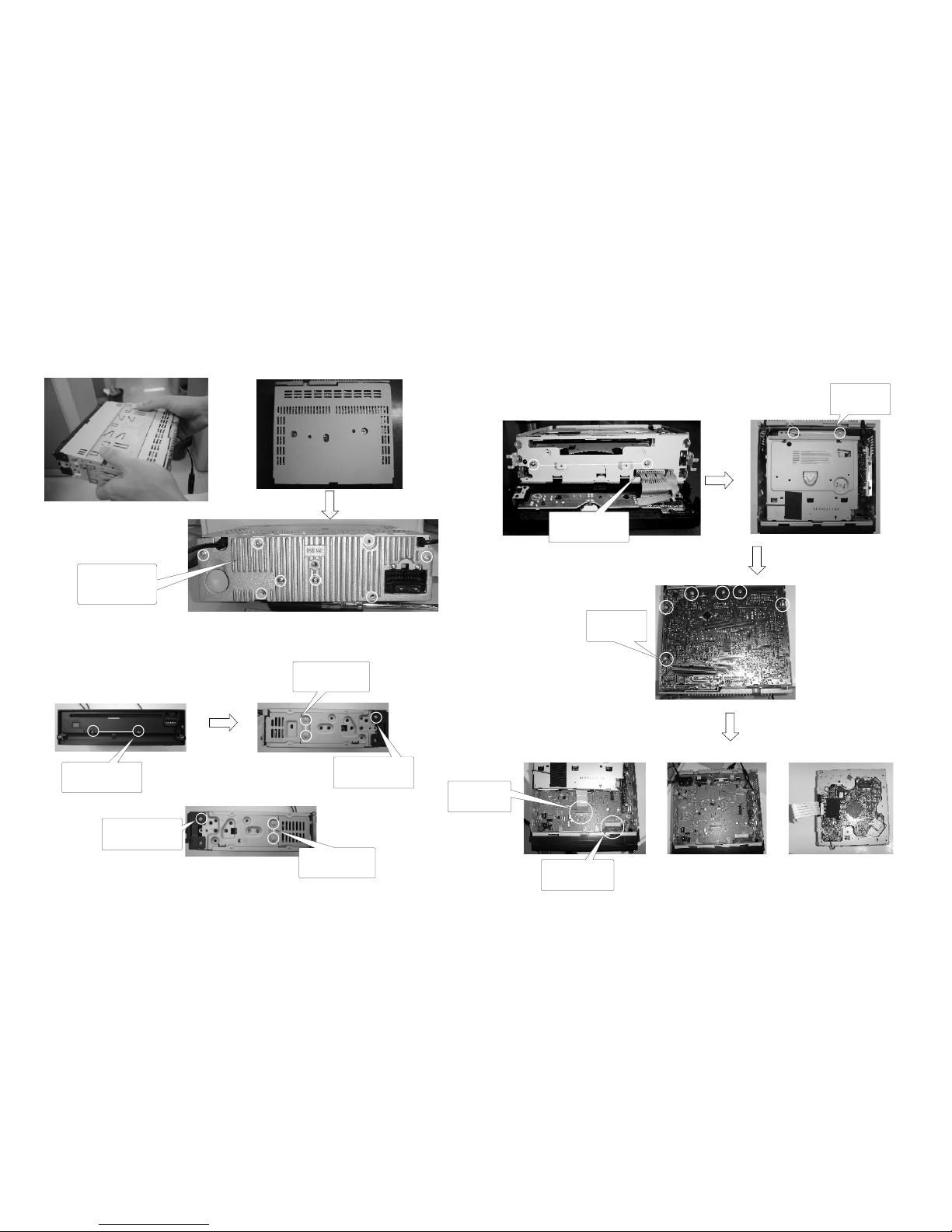
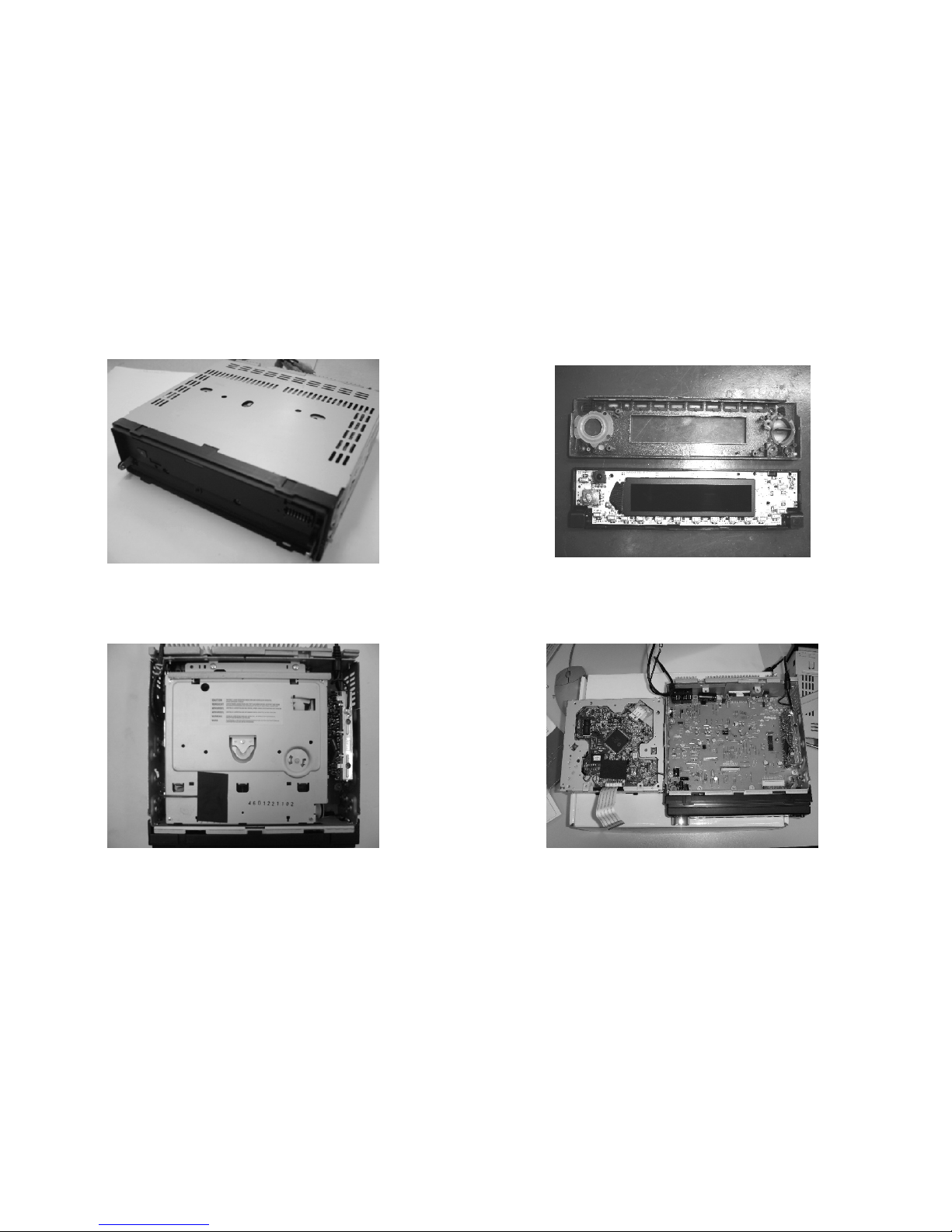
DISMANTLING INSTRUCTIONS
2-1
R
Remove 2 pcs
screw on the
top of loader.
2 emove top and bottom covers. 4Remove CD loader
1 Pull out the short sheet from main set.
3 Loosen 4 pcs screw to remove Front Cabinet.
Remove 2 pcs screw
from front cabinet.
Remove 2 pcs screw
from metal side.
Remove the screw
on the left side of
the cabinet.
Loosen 8 screws to
remove heatsink &
top cover & bottom
cover.
Remove the 2 pcs
screw to dismantle
the frame.
Remove 6 pcs
screw on the
main board.
Pull out FPC
wire.
Remove the
connector from
the mainboard.
Remove the 2 pcs
screw to dismantle
the frame.
Remove the screw
on the right side of
the cabinet.
2-2
DISMANTLING INSTRUCTIONS
2-2
Service Position A
Service Position B
Service Position C
Service Position D

Elect r ic Sele c tor & Vol u me
PT231 3
Pre-Amp
RC4558
Pre-Amp
RC4558
LCD Dis p lay
MCU
LCD Dri v er
LC652 3
IN1
MUTE
ST-BY
IN2
OUT1+
OUT1-
OUT2+
OUT2-
PW-GND
IN3
IN4
OUT3+
OUT3-
OUT4+
OUT4-
PW-GND
PW-GND
AC-GND SVR TAB S-GND
Vcc1 Vcc2
N.C.
Power Amplifier
TDA7384
PW-GND
F/ L
F/ R
R/ R
R/ L
LC D Da ta
LC D Cl oc k
LC D CE
Mu te
Li ne -O ut put
F/ R
F/ L
F/L
F/R
R/R
R/ L
F/L
F/R
R/R
R/L
El ec tr on ic Volu me C lo ck
LD-SW
KIN0-1
CL-SW
OP-SW
D1
D2
CLK
STB
RESET
KV5V-ON
El ec tr on ic Volu me D at a
B5 V
AC C
GN D
Power S u pply
DVD +9V
DVD+5V
AP1507
DC 1 1~ 16 V
Gr ou nd
D9 V
B5V
D9V
GN D
MC U DC 5 V
MC U DC 5 V ACC
DC 1 1~ 16 V
Co nt ro ll ed Powe r
AC C
SDRAM
M
Mot or D riv er
AM5 66 8
SPH E8 202 D VIDEO-OUT
MIC
ROM
(TSOP48PIN)
Ana log A udi o I/P
M
MIC
FLA SH M X29 LV8 00 T
DVD-R
DVD-L
DVD -PL AYE R 4-I N- 1 S IN GLE C HIP
1MX16X4BANK
(TS OP 115 4PI N)
Pre - Amp
RC4 5 58
Su b Ou t
AU X- IN
AU X R
AU X L
L R
CD -L
CD -R
Tuner Module
CET-7 0 00
Tu ne r R
Tu ne r L
AM /F M IF
AM O SC
FM O SC
Tu ne V ol ta ge
Lo ca l/ DX
Ra di o DC 5 V
Tu ne r Po we r
Tune r p l l u nit
13
LC720
St er eo I co n In
St at io n De tec t In
/
PL LC E
PL LD O
PL LD I
PL LC L
FM /A M VT
Remote-IR
Loading Motor -
BA6287
Lo ad in g Mo tor +
IR
3 3
SET BLOCK DIAGRAM
TMP86FS49

4 4
SET WIRING DIAGRAM
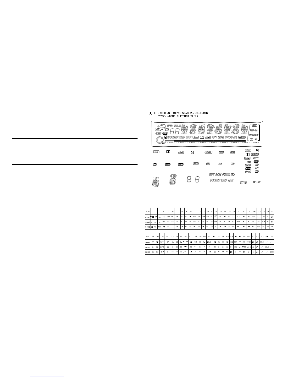
5-1 5-1
LCD PIN CONNECTION
KEY BOARD
PIN SEGMENT DISPLAY
TABLE OF CONTENTS
LCD Display . . . . . . . . . . . . . . . . . . . . . . . . . . . . . . . 5-1
Circuit Diagram . . . . . . . . . . . . . . . . . . . . . . . . . . . . 5-2
Layout Diagram . . . . . . . . . . . . . . . . . . . . . . . . . . . . 5-3
Electrical Parts List . . . . . . . . . . . . . . . . . . . . . . . . . 5-4
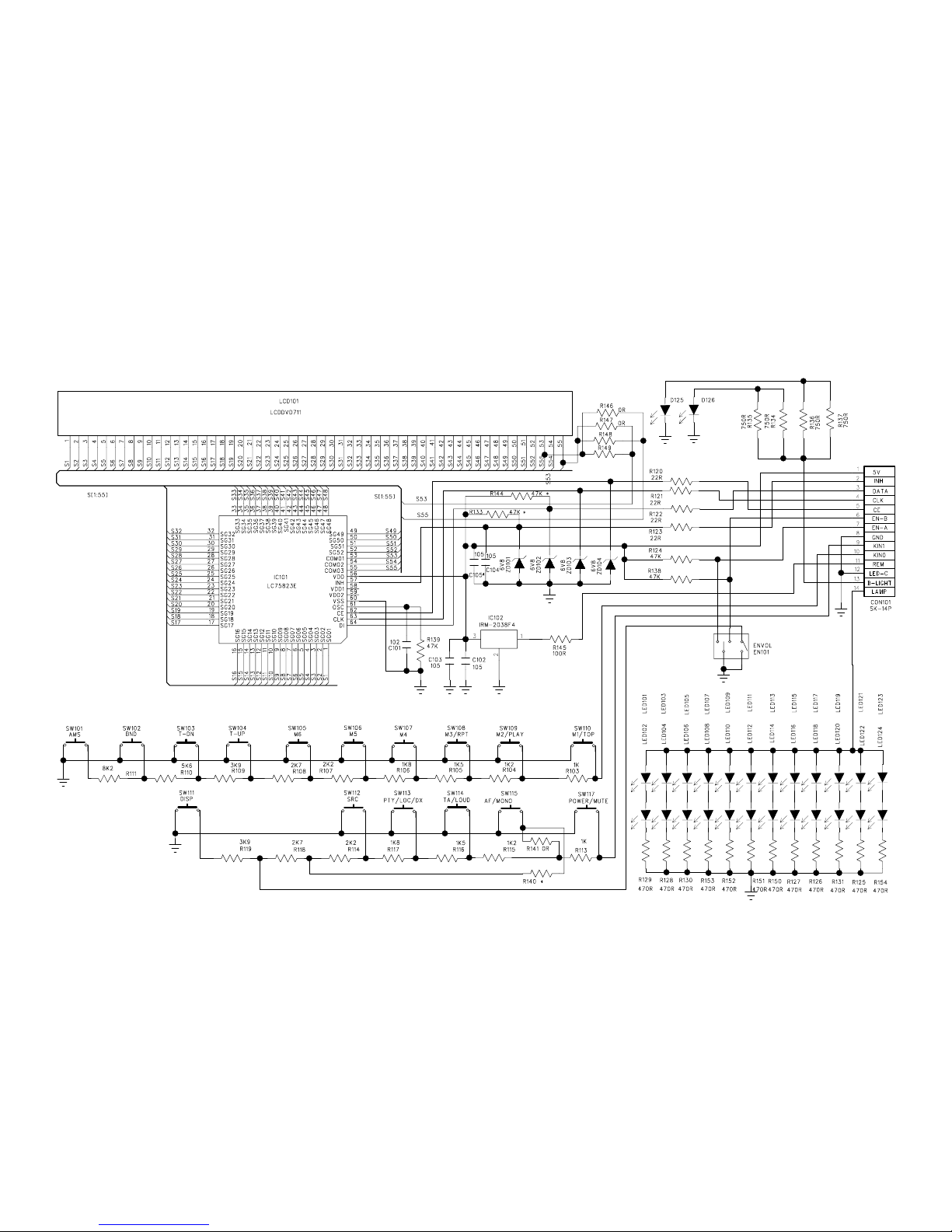
5-2 5-2
CIRCUIT DIAGRAM - KEY BOARD
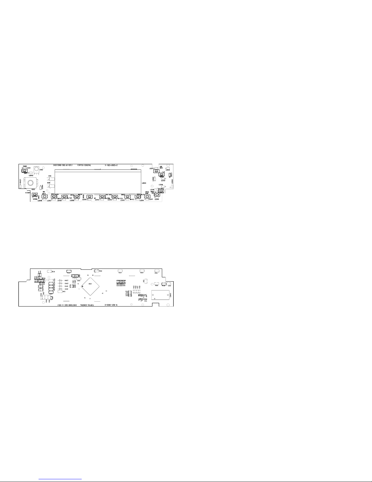
5-3 5-3
LAYOUT DIAGRAM - KEY BOARD
TOP VIEW
LAYOUT DIAGRAM - KEY BOARD
BOTTOM VIEW

5-4 5-4
ELECTRICAL PARTS LIST - KEY BOARD
Part No. Description
QTY
Location
83802DVD730EKB000
143010000259
143405000069
142400000338
121604000000
121604000220
121606000101
121604000473
121606000751
121604000122
121604000182
121604000272
121604000392
121604000562
121604000102
121604000152
121604000222
121604000822
121606000471
121806000105
121803000102
143210000016
123805000016
141662000008
143400000009
142212010002
121490000120
DVD730 RED KB SMT Assm
PCB,KB,DVD730,FR4,1.2mm,165X40.5mm
LED,RED,0603,10mA,2.2V
IC,SC75823E,QFP-64-14X14-0.8,SL
RES,0Ω,±5%,1/16W,0603
RES,22Ω,±5%,1/16W,0603
RES,100Ω,±5%,1/10W,0805
RES,47KΩ,±5%,1/16W,0603
RES,750Ω,±5%,1/10W,0805
RES,1K2Ω,±5%,1/16W,0603
RES,1K8Ω,±5%,1/16W,0603
RES,2K7Ω,±5%,1/16W,0603
RES,3K9Ω,±5%,1/16W,0603
RES,5K6Ω,±5%,1/16W,0603
RES,1KΩ,±5%,1/16W,0603
RES,1K5Ω,±5%,1/16W,0603
RES,2K2Ω,±5%,1/16W,0603
RES,8K2Ω,±5%,1/16W,0603
RES,470Ω,±5%,1/10W,0805
CAP,0805,105,50V,Y5V,+80%-20%
CAP,1nF,±10%,16V,X7R,0603
TACT SW,KPS-1107YB-130
o
14PIN,2.0mm,SOCKET MALE ESTF2-14-01(90 )
ENCODER,ECB12,(7X5)(PV)S17
DVD711,NEGATIVE COLOR,JIC-TB6240N
PHOTO DIODE,IRM2,638AF4,5V/1.1
CM203,ZEBRA STRIP
1
1
24
1
3
4
1
3
4
2
2
2
2
1
2
2
2
1
12
3
1
16
1
1
1
1
1
LED101~LED124
IC101
R141,R146,R147
R120~R123
R145
R124,R138,R139
R134~137
R104,R115
R106,R117
R108,R118
R109,R119
R110
R103,R113
R105,R116
R107,R114
R111
R125~131,R150~154
C102,C103,C104
C101
SW101~SW115,SW117
CON101
EN101
LCD101
IC102

6-1 6-1
SERVO BOARD
TABLE OF CONTENTS
Circuit Diagram . . . . . . . . . . . . . . . . . . . . . . . . . . . . 6-2
Layout Diagram . . . . . . . . . . . . . . . . . . . . . . . . . . . . 6-3
Electrical Parts List . . . . . . . . . . . . . . . . . . . . . . . . . 6-4
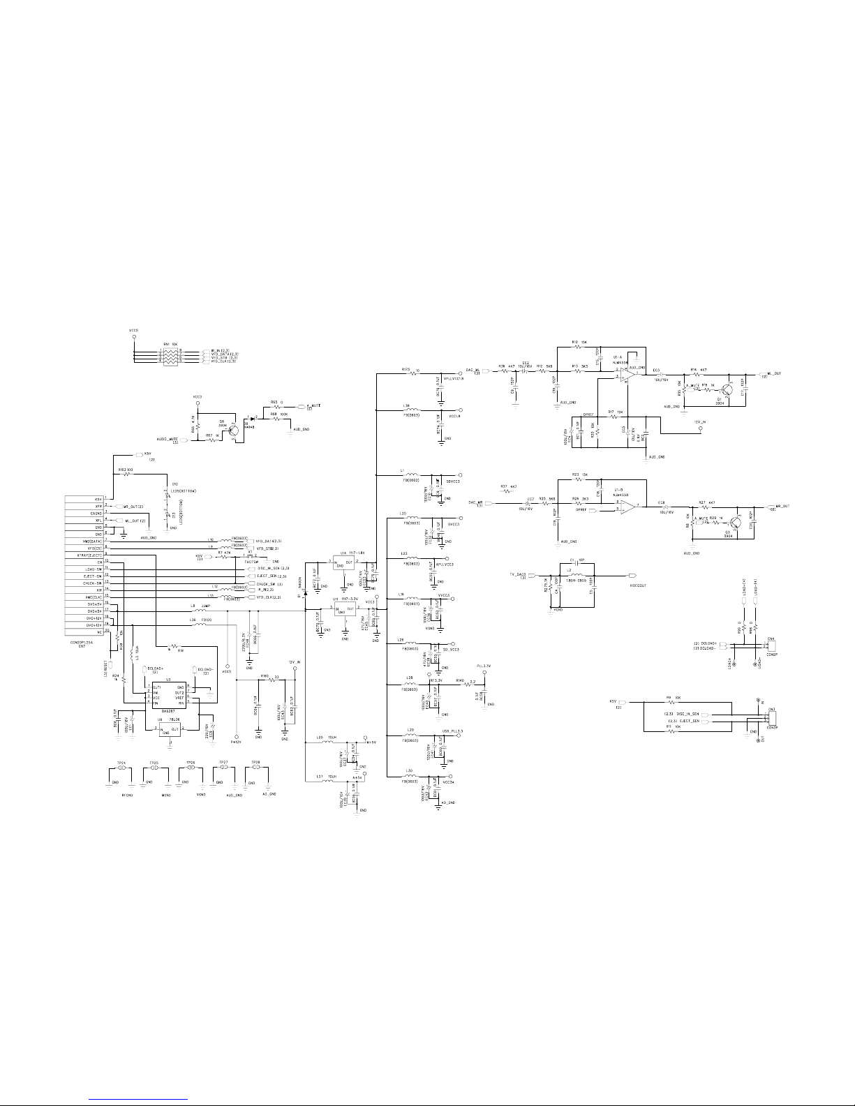
6-2 6-2
CIRCUIT DIAGRAM - SERVO BOARD
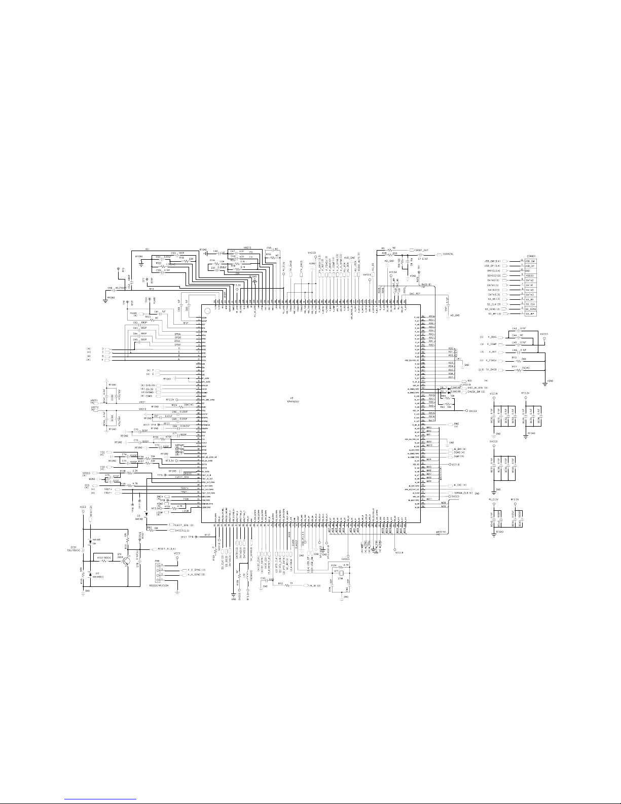
6-3 6-3
CIRCUIT DIAGRAM - SERVO BOARD
Table of contents
Other Elenberg Car Stereo System manuals


 operating instructions")


