Elite Entry Phone Dial Code User manual

DIAL CODE LC SERIES
OWNERS MANUAL
Telephone entry system with two line large liquid crystal display
www.eliteentryphone.com
VISIT US ON THE WEB
MADE IN USA
®

1
PAGE
TABLE OF CONTENTS
Please do not attempt to
repair the Entry Phone
unless you are an autho-
rized service technician!
Thank you.
© 1997 BY ELITE ENTRY PHONE -
ALL RIGHTS RESERVED. NO PART
OF THIS MANUAL MAY BE REPRO-
DUCED IN ANY MEANS GRAPHIC,
ELECTRONIC OR MECHANICAL,
INCLUDING PHOTOCOPYING WITH-
OUT THE EXPRESSED WRITTEN
PERMISSION OF THE PUBLISHER.
MATERIALS, COMPONENTS AND
SPECIFICATIONS ARE SUBJECT TO
CHANGE WITHOUT NOTICE.
RELEASE 1
LCD MANUAL
VERSION 1.31
DECEMBER 1999
Screen Saver Mode
Entry Phone Features
Mounting Installation
Postal Lock Installation
Port Connectors
Memory Card Installation
Viewing Software Version
Connecting Keypad Light Wires
Programming the Processor
Selecting Program Mode
Tenant Information
Area Codes
Utility Codes
Password
Clock Timer
Strike Time
Resident Use
Talk Time
4
5 - 7
11 - 12
10
8
Wiring Diagram 9
15
RF & RS485 Connections 13 - 14
15
16
Warnings and Precautions 16
17
18
19
21
22
23
24 - 26
27
3 - 4
Product Overview 2
27
Report Printing 28
Volume Adjust
Backup Memory
Error Messages
Parts List & Diagram
Approvals
Greeting 29
29
30
31
32
33
Transmitter/Card Programming 20

PRODUCT OVERVIEW
2
PAGE
• Two line Large LC Directory.
• Names listed in Directory in alphabetical order.
• Memory capacity: 25, 50, 150, 250, 500, 1000 names.
• User-friendly programmability via built-in alpha-numeric
keyboard eliminates the need for user's manual.
• Four character alpha-numeric password required to enter
programming mode.
• Programmable Utility keycodes for keyless entry.
• 60 Utility keycodes available per system.
• Time zones associated with Utility keycodes.
• Programmable real-time clock with leap year & daylight
savings compensation.
• 2 programmable 7-day timers for door and gate control.
• Programmable talk time.
• Touch-tones through microphone are ignored by system.
• System mutes tones in speaker during dialing.
• Postal lock capability.
• Surge protection;
• Power line: 5,000 volts surge protection.
• Tel line:800V (100A) surge protection.
• Immune to 25,000V electrostatic discharge.
• Two output relays with independent strike times.
• Relay output for VCR time lapse recorder to record 5
seconds per transaction.
• Power failure backups:
• Battery backup for complete function for 5 hrs.
• Battery enables dial out, program, & display.
• Non-Volatile removable SRAM memory has
unlimited write cycles (unlike EEPROM).
• Non-Volatile Real Time Clock/Calendar.
• High quality voice communication system with back-
ground noise filtering.
•Voice messages (digital) to help & guide user.
•Volume control via software.
•Non-Volatile PCMC 1A memory card
•Two (2) slots for PCMCIA memory cards. Second slot
used for file backup.
•Double box with built-in full keyboard for data processing.
•Parallel printer interface common to all computer printers.
•Print reports of programmable information.
•Printer error/Paper empty detection.
•By pressing '9' for gate or '5' for door, communication is
not lost. Talk time is extended to avoid unpleasant cutoff
between visitor and resident.
•Both DTMF tone and rotary dial detection.
•Programmable via modem-2400 bps (optional).
•FCC part 68 ,15 & Canadian DOC approval
• Construction: Front Panel: 16 gauge stainless steel.
Processor Containment Box: Gold/zinc plated, powder
coated 16 gauge metal (weather resistant finish)
• Entire system is rain resistant.
• Power Input: 12 VAC, 40VA UL listed transformer(provided).
• Jack Type: USOC RJ11C or W
• Operating Environment:
• Temperature: -40 F to +185 F.
(Heater kit available at additional cost.)
• Relative Humidity: 5% - 95% non-condensing.
• Dimensions: 11 1/4" W X 16 7/16" H X 3 3/16" D
• Shipping Weight: Approximately 25 lbs.
FACTORY TO DEALER
3 YEAR WARRANTY
STANDARD FEATURES
SPECIFICATIONS

RESIDENT USE
3
PAGE
Welcome To
Elite Entry
(fig a.)
Fairbanks, George
CODE: 012
(fig c.)
Fairbanks, George
DIALING! CODE: 012
(fig d.)
TIME TO TALK> 17 SEC
___
(fig e.)
(fig b.)
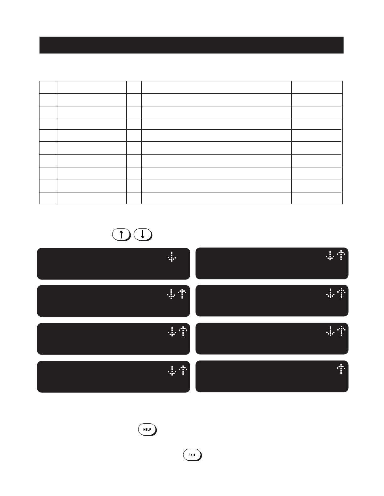
Use Keys
To View Directory
When operating, the Entry Phone System will alternate between the “Welcome” screen (fig a.) and the “View Directory”
screen (fig b.).
By pressing or dialing the number “9” on their digital
or rotary phone,
By pressing or dialing the number “5
”
on their digital
or rotary phone,
the resident will open the door or pedestrian gate.
Entry 2
the resident will open the vehicular entrance gate.
Entry 1
Use the keys to scroll up and down
through the names listed in the Entry Phone’s electronic
directory as shown in (fig c.) The names are listed in
alphabetical order by last name.
When the desired name is found, enter the corresponding
3-digit code. The system will dial the number assigned to
the tenant code entered. (fig d.) After connecting, the
screen will display the talk time as shown in (fig e.) If the
resident wants to allow access to the visitor, they simply
press (or dial) “9” for vehicular gate entrances, or “5” for
door or pedestrian gate . If the resident wants to deny
access, they simply hang up the phone.
OR
OR 5
9
JKL
WXY

RESIDENT USE
4
PAGE
USING KEYCODES AND UTILITY CODES (ACTIVE ENTRY 1 ONLY)
SCREEN SAVER MODE
* ACCESS GRANTED *
Please Enter
(fig a.)
* ACCESS GRANTED *
Please Enter
(fig c.)
PRESS ANY KEY
(fig e.)
* INVALID ENTRY *
Invalid 6-Digit Code
(fig b.)
* ACCESS DENIED *
Not In Access Period
(fig d.)
Residents are assigned a 6-digit, personalized key-
code for accessing the facility. To use the keycode
assigned, the resident must first push the
key once and enter their keycode. The screen will
display “Access Granted” (fig a.) and access will be
allowed. If an incorrect keycode is entered, the sys-
tem will inform the user of the invalid entry (fig b.)
The resident can then re-enter their keycode.
RESIDENT 6-DIGIT KEYCODES
All systems, no matter what the memory capacity,
are equipped with 60 different Utility codes. To
access the facility within the time zone set, the
Utility Company must first press the key
TWICE and then enter their 4-digit code. If it is
within the programmed time zone for entry, the
screen will display “Access Granted” (fig c.) and
access will be allowed. If, however, it is not within
the time zone for entry, the display will inform the
user and access will not be allowed (fig d.)
If the Dial Code System is inactive for 15 seconds it
will go into sleep mode. The screen will continue to
display the scrolling message “Press Any Key”
until a key is pressed. The Screen saver mode is not
available while in program mode.
INDIVIDUAL UTILITY CODES
EXAMPLE - UTILITY CODE 8716 = 8 7 16
EXAMPLE - KEYCODE 002543 = 0
02543

ENTRY PHONE FEATURES
5
PAGE
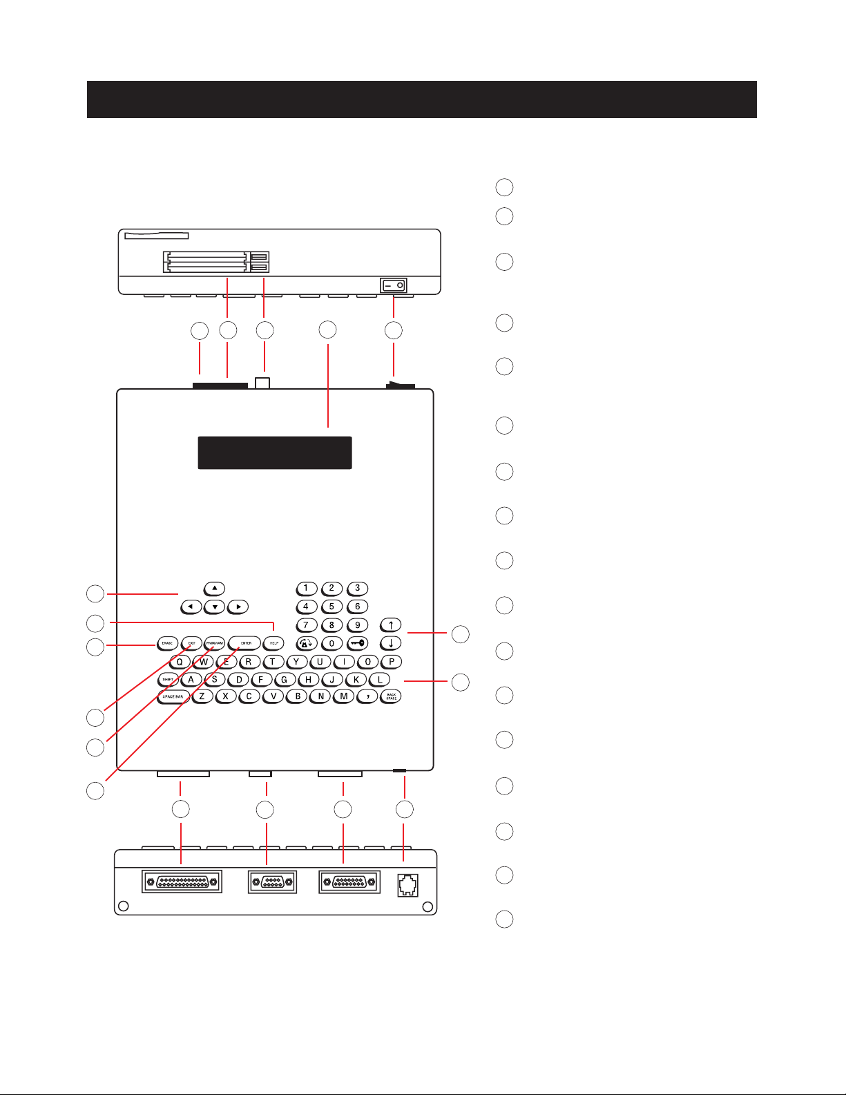
Backup Memory Card Slot
Display
Window
Dialing Keys
Key Lock
External
Keypad
Stainless
Steel Door
External
Speaker
Processor Key Release / Lock
Mounting Hole
Mounting Hole
Memory Card
LC Display
Processor Unit
Programming Keys
Printer Parallel Port
Optional RF
Receiver Mount
Communication Port
Input/Output Connector
Conduit Knock-outs
Phone Jack (RJ11)
Mounting Hole
Postal Lock Setup
Power Switch
Mounting Hole External Microphone
Memory Card Release Buttons
Memory Card Slot
Processor
Containment Box
All components and specifications are subject to change without notice.

123
456
78 A
HELP
Z
9
0
ENTRY PHONE FEATURES
6
PAGE
EXTERNAL MICROPHONE
KEY LOCK - Opens the Processor
Containment Box to access the
Processor.
HELP KEY - With digital voice mes-
sages to help guide the user.
EXTERNAL SPEAKER
DISPLAY WINDOW - Heavy-duty, 3/8”
thick protective lens.
DIALING KEYS LIGHT - Lights up
dialing keys for easy visibility.
PHONE DIALING KEYS - Used to dial
residents / keycodes
SCROLL KEYS - Scrolls through
names in alphabetical order on
screen.
UNLOCK KEY - Residents and utility
personnel use this key with their key
code to open gate.
HANG-UP KEY - Pressed when user
wants to hang up.
ACCESS FOR POSTAL LOCK
16 GAUGE STAINLESS STEEL DOOR -
Heavy-duty and weather resistant.
1
1
2
3
4
7
8
9
10
11
12
5
2
3
4
5
6
7
8
9
10
11
12
6
All components and specifications are subject to change without notice.
ENTRY PHONE FEATURES
7
PAGE
POWER ON/OFF SWITCH
MEMORY CARD RELEASE BUTTONS - Eject
Memory Cards when pressed.
CARD SLOTS - Front slot holds Backup Memory
Card or RF Card, back slot holds Main Memory
Card.
MEMORY CARD - Stores all programmed
information.
TWO LINE, LARGE LIQUID CRYSTAL DISPLAY -
Displays information and instructions,
two lines at a time.
DIRECTION KEYS - Move cursor to desired
position within screens.
HELP KEY - Helps user while in programming
or user modes.
ERASE KEY - Erases information screens
no longer needed.
EXIT KEY - Press this key to go back to previous
screen / menu.
PROGRAM KEY - Sets Processor to program
mode.
ENTER KEY - Registers information into memory
after it is typed.
PRINTER PARALLEL PORT - Enables printing of
programmed information.
COMMUNICATION PORT - RF Interface for future
remote control and card access use.
INPUT/OUTPUT CONNECTOR - Main power,
input/output connection.
PHONE JACK (RJ11) - Connects to main
phone line.
KEYBOARD - Works like standard keyboard to
type in information and names.
SCROLL KEYS - Scrolls through screens /
menus.
13
13
14
15
16
17
18
19
20
21
22
23
24
25
26
27
28
29
17
14
15
16
18
19
20
21
22
23
24 25 26 27
28
29
All components and specifications are subject to change without notice.
MOUNTING INSTALLATION
8
PAGE
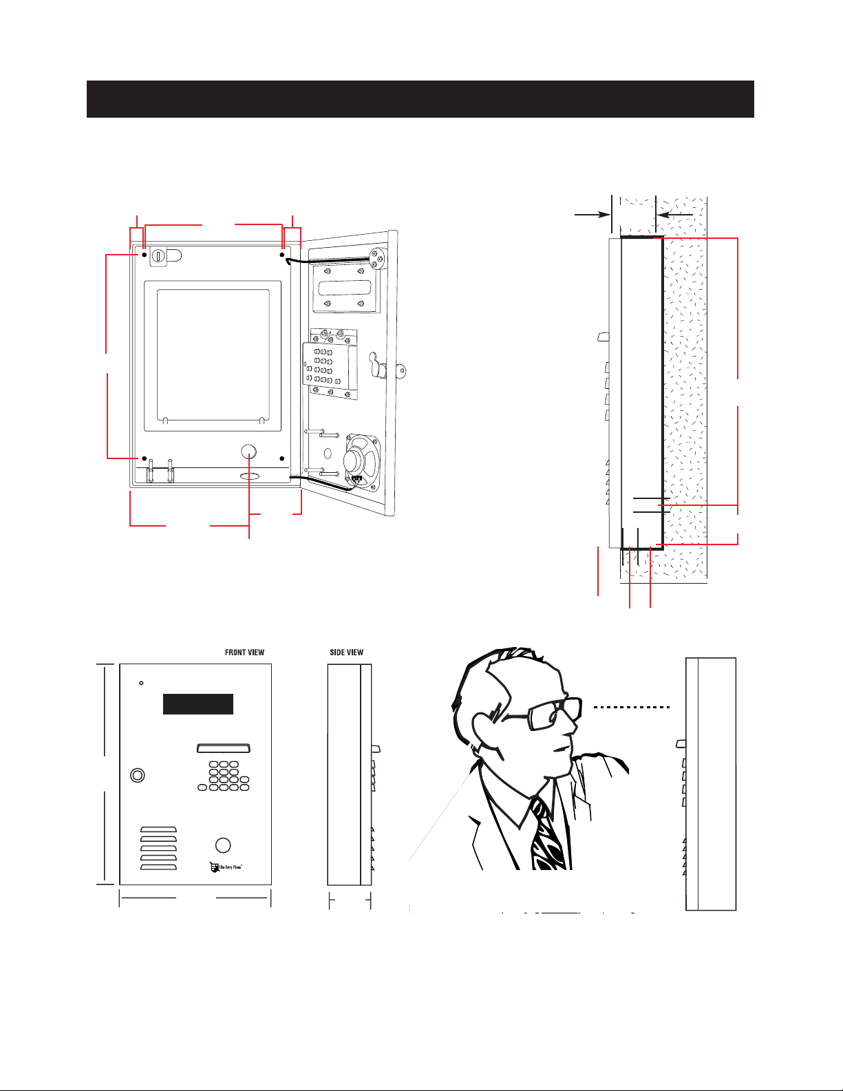
WALL
MOUNTING HOLES 1/4” dia.
CONDUIT KNOCK-OUTS 7/8” dia.
2 1/8”
1 1/16”
8 3/4”
14 1/2”
6 3/4”
4 1/2”
14 9/16”
2 1/2”
1 7/8”
FOR INSTALLATION
ON WALL
Remove the Processor
Unit from the Processor
Containment Box and
bolt the Processor
Containment Box to
recess in wall using the
four mounting holes.
Feed the power and
phone lines through the
appropriate holes for
connecting to the
Processor Unit.
NOTE: Be sure to install the Entry Phone at normal eye level
16 7/16”
11 1/43 3/16
All components and specifications are subject to change without notice.
1.5”
1”
WIRING DIAGRAM
9
PAGE
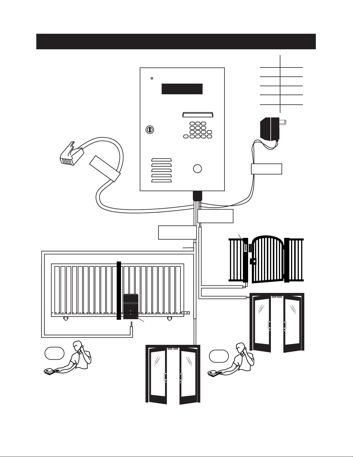
2 BLUE WIRES
ENTRY 2
BLACK/WHITE
2 YELLOW WIRES
ENTRY 1
USOC RJ11C
12VAC 40VA
see chart above
for distance
CONDUIT
AWG
24
22
20
18
16
170’
280’
450’
700’
1100’
MAX.
DISTANCE
“DEDICATED”
TELEPHONE LINE
VEHICULAR GATE
OR
ENTRY DOOR
LOCK
MASTER GATE OPERATOR
(STRIKE OPEN INPUT)
ELITE ENTRY PHONE
ACCESS DOOR
Connect the two blue wires to the secondary
gate or door. The gate/door will only be
activated from the residents side by pressing 5.
(Refer to page 27 to adjust the strike times).
OR 5
WXY
9
WXY
Connect the two yellow wires to the main
vehicular gate operator or door. The gate/door
will be activated by either pressing 9 from the
residents side, or by using a utility keycode,
individual keycode or optional RF transmitter
from Entry Phone side. (Refer to page 12 &
13)
PEDESTRIAN GATE
POSTAL LOCK INSTALLATION
10
PAGE
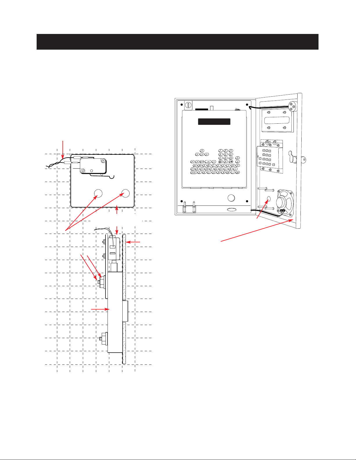
(Retain nuts and washers) Install the postal lock with the
sliding bolt oriented away from the speaker.
Install the enclosed plate end switch assembly over the
sliding bolt so that when the bolt is extended it will activate
the switch as shown in the diagram.
Fasten by using the enclosed flat washer, lock washer, and nut
on each of the four studs. Adjust the plate and switch location
as the nuts are tightened to ensure switch activation when the
bolt is extended.
Connect the two wires from the postal lock switch in parallel
with either the two blue wires (door relay) or the two yellow
wires (gate relay) at the 15 pin input/output connector. Note
that polarity or color coding is not required. As example: If
you wish to activate the door using the postal lock switch,
connect wire 1 from the switch to one of the blue wires and
connect wire 2 from the switch to the other blue wire.
Test operation by activating the lock. Ensure that full
extension of the sliding bolt will not bend or break the switch.
These parts are used only when postal access to your facility is required. The postal lock mecha-
nism must be obtained by application to your local post office.
Installation: Open the front panel of the Entry
Phone and remove the hole plug.
KNOCK OUT HOLE FOR POSTAL LOCK
SWITCH ASSEMBLY
MOUNTING HOLES
(MOUNT WITH POSTAL LOCK ON
ENTRY PHONE FRONT PANEL)
POSTAL LOCK
STAINLESS STEEL FRONT PANEL
POSTAL LOCK SWITCH WIRES (2)
POSTAL LOCK
SWITCH ASSEMBLY
11
PAGE
Speaker Terminal 1
Speaker Terminal 1
VCR Relay N O (green)
VCR Relay COM (green)
Gate Relay N O (yellow)
Gate Relay COM (yellow)
Door Relay N O (blue)
Door Relay COM (blue)
Heater (red)
12VAC Transformer / Heater (white)
12VAC Transformer (black)
Microphone (+)
Microphone (-)
INPUT/OUTPUT PORT CONNECTOR
15 Pin
Input / Output
Connector
USOC RJ11C
Telephone Line
(included)
OPTIONAL
9-Pin Communication port
connection - for optional
RF and RS-485 products
OPTIONAL
Parallel Printer Port
connection see page 28
Entry Phone Processor
1
1
2
2
3
3
4
4
5
5
6
6
7
8
7
8
SPEAKER TERMINAL: Pre-installed speaker output.
VCR RELAY: For use with Time Lapse VCR. Each time
access is granted, the VCR Relay is activated for 5
seconds, allowing recording of all access to facility.
HEATER: For use with the white wire to allow
optional heater kit to be connected. Relay goes on at
0°f and off at 20°f.
GATE RELAY: for use with gate operator to
control access through main vehicular gate.
DOOR RELAY: For allowing access through pedestri-
an gate or door.
12 VAC: Power supply to the Entry Phone.
MICROPHONE: Pre-installed microphone input.
TELEPHONE LINE: Standard USOC RJ11C phone line
(included) to be connected to standard phone jack.
Telephone line used for phone entry system must
be a dedicated line.
NOTE:
12
PAGE
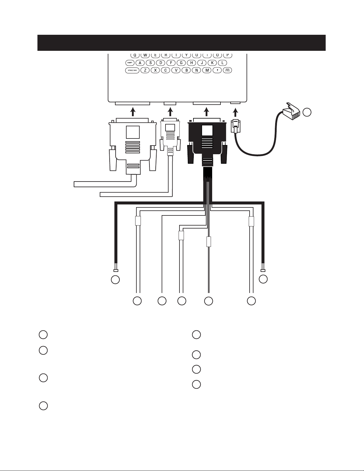
COMMUNICATION PORT CONNECTORS
15 Pin
Input / Output Connector
USOC RJ11C
Telephone Line
(included)
OPTIONAL
9-Pin Communication
port connection - for
optional RF and RS-485
products
OPTIONAL
Parallel Printer
Port connection
see page 28
Entry Phone Processor
1
2
3
21
RF RECEIVER: For use with local RF receiver. (See Receiver Connection Manual.)
RS485: Connect to corresponding RS485 terminals (-, +, GND) of remote security devices.
TELEPHONE LINE: Standard USOC RJ11C phone line (included) to be connected to standard phone jack.
RF Receiver (Data) (green)
RF Receiver (Power) (black)
RF Receiver (Ground) (white)
RS485 (+) (brown)
RS485 (Ground) (Yellow)
RS485 (-) (blue)
3

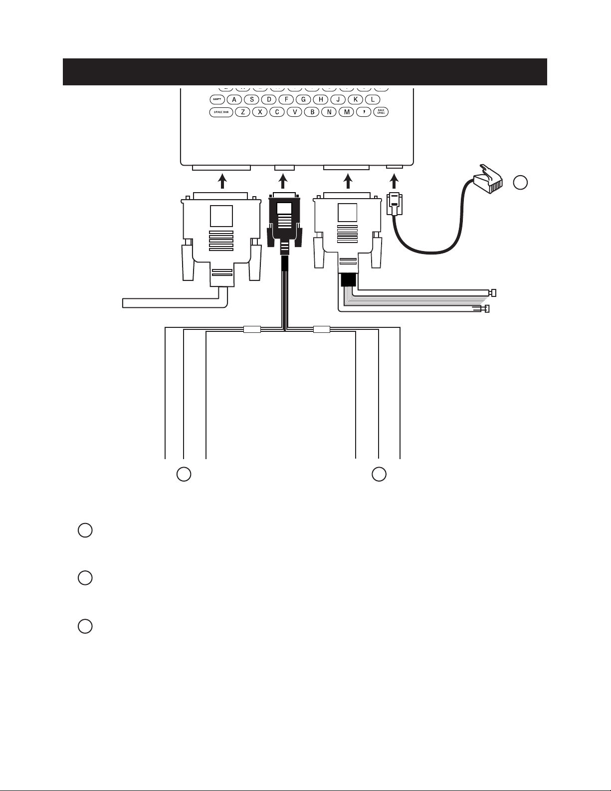
RS-485 CONNECTION EXAMPLE
13
PAGE
KEYPAD
RS 485 REMOTE DEVICE 1
CARD READER
RS 485 REMOTE DEVICE 3
STAND-ALONE RECEIVER
RS 485 REMOTE DEVICE 2
LOCAL
RF RECEIVER
UNIVERSAL INTERFACE BOARD
RS 485 REMOTE DEVICE 4
RF Receiver wires
1 2 3
4 5 6
7 8 9
*0 #
GREEN
BLACK
WHITE
RS485
wires
RS485 GND (yellow)
RS485 (+) (brown)
RS485 (-) (blue)
NOTE: To support RS485 devices you must install the Communicator Card.
14
PAGE
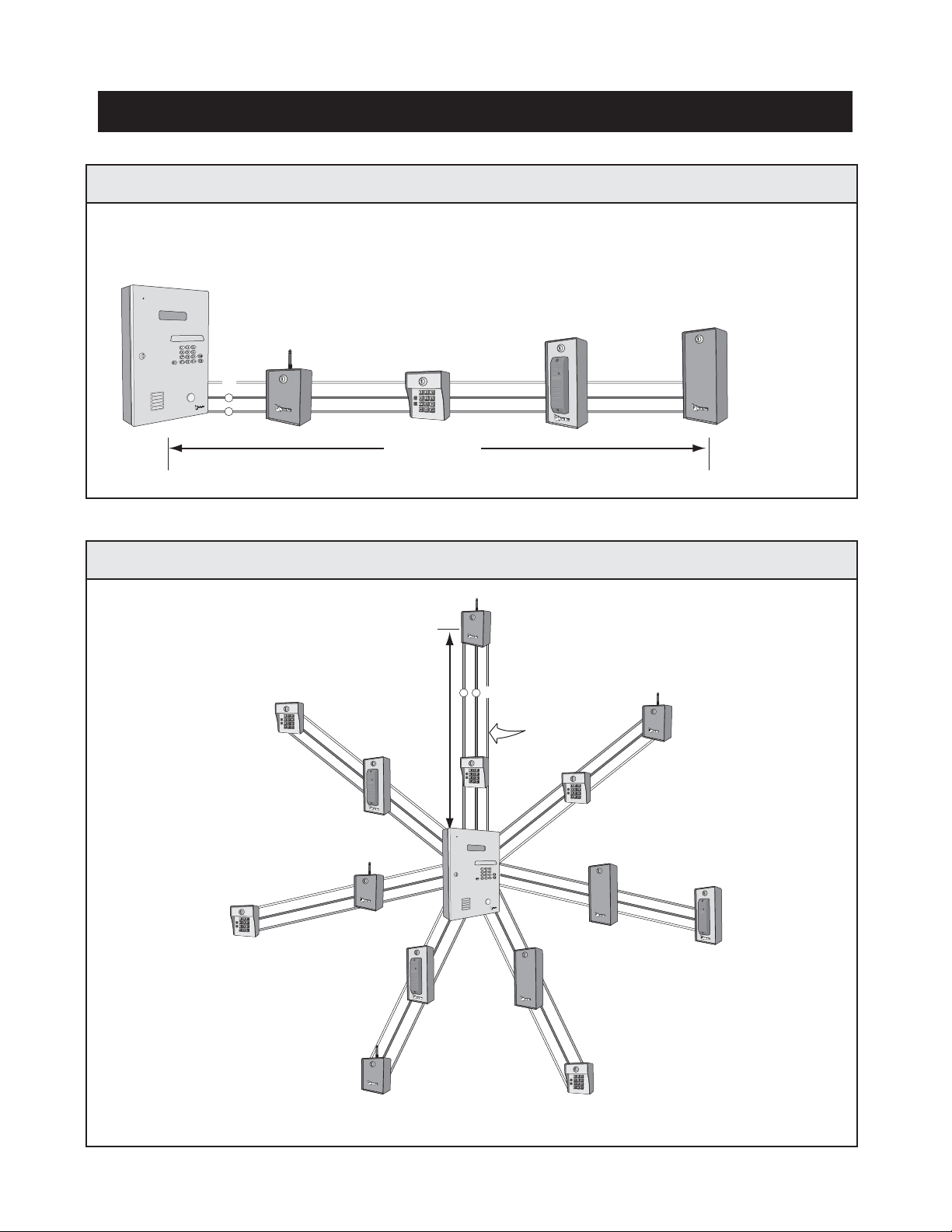
RS-485 CONNECTION CONFIGURATIONS
• Up to 31 RS-485 devices supported
• Maximum distance from the last RS-485 device to the Entry Phone is 4000 Ft.
• Turn “ON” the terminator switch ONLY for the last device installed in the RS-485 line.
• Use 22 AWG twisted pair shielded wire
Each RS-485 device must have a unique “Device ID Number” set by using the rotary switches on the device. (Refer to specific RS-485 Instruction sheets).
Each RS-485 device must have a unique “Device ID Number” set by using the rotary switches on the device. (Refer to specific RS-485 Instruction sheets).
Turn Terminator Switch “ON”
for Last Device on Wire Run
Turn Terminator Switch “ON”
for Last Device on Wire Run
Turn Terminator Switch “ON”
for Last Device on Wire Run
Turn Terminator Switch “ON”
for Last Device on Wire Run
Turn Terminator Switch “ON”
for Last Device on Wire Run
Turn Terminator Switch “ON”
for Last Device on Wire Run
Turn Terminator Switch “ON”
for Last Device on Wire Run
Turn Terminator Switch “ON”
for Last Device on Wire Run
“Daisy Chain” wiring configuration
(Recommended method for superior data transmission)
“Star” wiring configuration
• Maximum number of wire runs allowed is 7
• Maximum distance from the last RS-485 device
(per wire run) to the Entry Phone is 4000 Ft.
• Maximum number of RS-485
devices present on ALL wire runs
is 31.
• Use 22 AWG twisted pair shielded wire
Wire Run
Configuration #1
Configuration #2
4000 Ft Max.
4000 Ft Max.
+
–Gnd
+
–
Gnd
MEMORY CARD INSTALLATION
15
PAGE
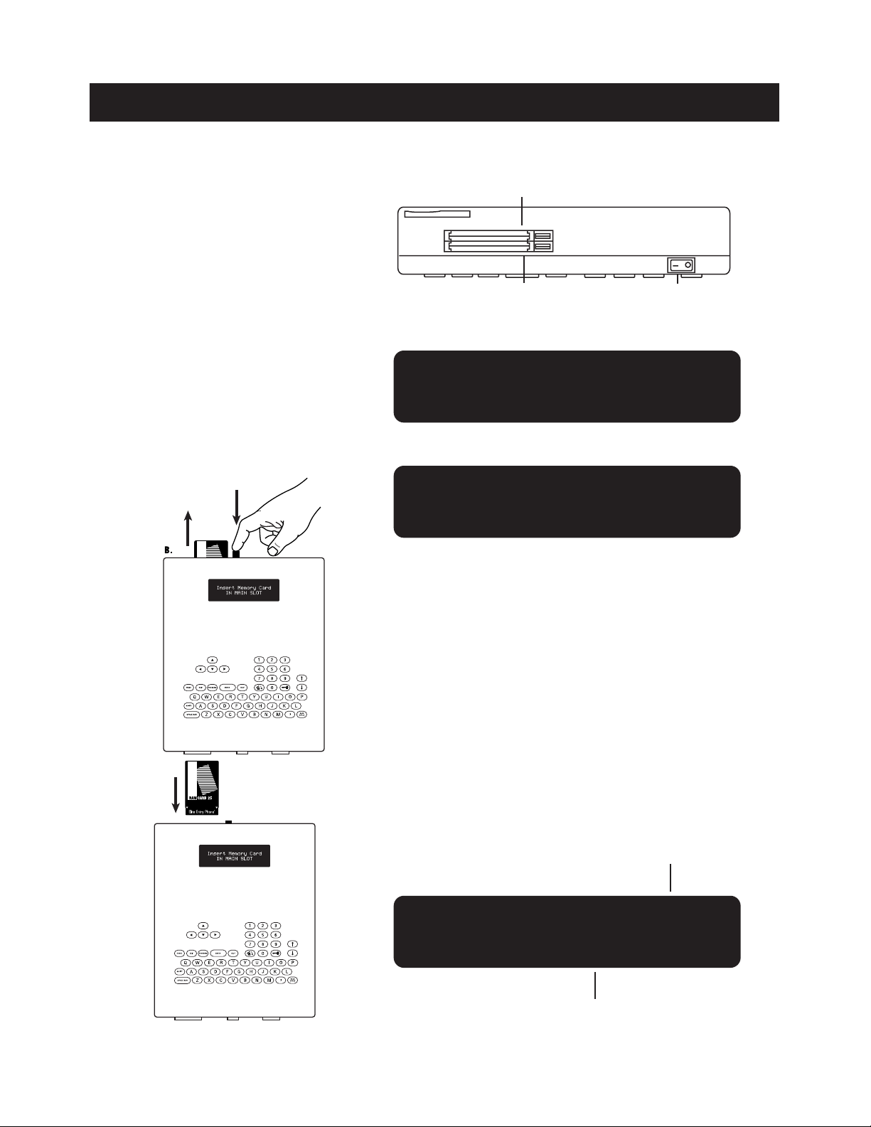
A. Turn power on and insert Memory
Card into Main Memory Card Slot
(Main Memory Card in back slot,
Backup Memory Card in front slot.)
(fig a.) Push it all the way in until card
“snaps” into place and the release
button pops up. The screen should
display the “Welcome Screen” (fig b.)
A. To view the memory capacity of the system or to view
the software version currently running on the system in
operation an information screen is accessible on all Dial
Code systems for easy reference. Turn power off and insert
Memory Card in Main Memory Slot. Turn power on and the
information screen should display as seen in (fig e.)
B. If the screen continues to display
the “Insert Memory Card” screen
(fig c.) then Eject memory card by
pressing the corresponding release
button down and reinsert Memory
Card into main slot (fig d.). Otherwise
continue with programming.
MAIN MEMORY CARD
BACKUP MEMORY CARD OR
COMMUNICATOR CARD FOR
RF DEVICES/RS485
Welcome To
Elite Entry Phone
Insert Memory Card
IN MAIN SLOT
MEMORY CAPACITY
SOFTWARE VERSION NUMBER
(fig a.)
(fig b.)
(fig c.)
TOP VIEW OF PROCESSOR
POWER SWITCH FRONT
BACK
DIAL CODE VF-250
REV. 1.00_
(fig e.)
VIEWING THE SOFTWARE VERSION
(fig d.)

CONNECTING KEYPAD LIGHT WIRES
16
PAGE
WARNINGS AND PRECAUTIONS
A
B
250
A. The Entry Phone is only water resistant when the Stainless Steel
Door is closed and locked. Do not expose the Processor Unit or the
open Processor Containment Box to rain, snow, or harsh weather
conditions. Do not drop the Processor or expose it to impact.
B. Do not touch the terminals. Do not bend, drop or expose to impact.
IF YOU ARE USING THE PHONE’S OWN TRANSFORMER FOR POWER:
STEP 1 Unplug the transformer.
STEP 2 Connect the black and white wire on the light in parallel
with the black and white wires on the phone.
STEP 3 Stow the wires in the bottom of the box neatly.
STEP 4 Plug in the transformer. Test the phone for normal function.
All five lights in the hood should be lit.
IF YOU ARE USING A SECOND TRANSFORMER TO POWER THE LIGHT:
(Time clock or existing security lights)
STEP 1 Run your wires to a place to plug in the 12V transformer.
STEP 2 Wire the black & white wires to the 12V (AC or DC)
transformer per all local codes & standards.
STEP 3 Plug in the transformer. Test the phone for normal function.
All five lights in the hood should light with the power on.

PROGRAMMING THE PROCESSOR
17
PAGE
ENTERING THE PROGRAM MODE
When the Processor unit is turned on and the button is pressed, the screen will display:
If you enter the wrong password, the screen will prompt you to try again:
Press to retry entering your password. Press to quit the programming menu.
TO ENTER PROG MODE,
Type Password >____
Type in the factory present password (7777). Press . The Program Selection Screen
will display:
SELECT PROG MODE:
(N)Names (U)Utility
INVALID PASSWORD
(R)Retry (EXIT)Quit
R
Pressing the button will provide users with a help message.
IMPORTANT NOTE: While in the help screens, programming will be disabled.
To continue programming, press the button to exit the help screens first.
SELECTING PROGRAM MODE
18
PAGE
SELECT PROG MODE:
(N)Names (U)Utility
SELECT PROG MODE:
(P)Password
SELECT PROG MODE:
(C)Clock/Timer
SELECT PROG MODE:
(S)Strike Time
SELECT PROG MODE:
(T)Talk Time
SELECT PROG MODE:
(R)Report Printing
SELECT PROG MODE:
(G)Greeting
SELECT PROG MODE:
(V)Volume (B)Backup
*We recommend you customize your password to avoid unauthorized programming (see pg 23)
To select a Program Mode, press the corresponding letter from one of the ten options.
LIST OF PROGRAM MODES:
Names
Utility
Password*
Clock/Timer
Strike Time
Talk TIme
Report Printing
Greeting
Volume
Backup
page 19-21
page 22
page 23
pages 24-26
page 27
page 27
page 28
page 29
page 29
page 30
Program or edit Tenant Names
Program or edit Utility Codes
Program New Password ( recommended )
Program System Clock and Seven Day Timers
Program relay output time ( for 2 relays )
Program length of Talk Time
Program setup of different report printing
Program custom Welcome Screen Message
Program Volume level
Backup of memory card
1
2
3
4
5
6
7
8
9
10
N
U
P
C
S
T
R
G
V
B
Use the keys to scroll through the ten different Program Modes.
Pressing the button will provide users with a help message.
IMPORTANT NOTE: While in the help screens, programming will be disabled.
To continue programming, press the button to exit the help screens first.

19
PAGE
TENANT INFORMATION
SELECT PROG MODE:
(N)Names (U)Utility
PROG A NEW NAME N
PROG BY CODE:___
In the Program Selection Screen (fig a.), Press the key. The screen will display (fig b.):
You now have three options:
Tenant name
Tenant code
OR OR
STEP N
1
STEP 2
Type in the desired Tenant name, LAST name first, followed by the first name (fig c.). If the code you have
selected is already used, there will be a name already. You can edit the name by simply typing over it.
Press the key to complete the entry. You may also use the keys to move the cursor
within a code.
STEP 3
Type in the desired Tenant phone number (fig d.). If you need to enter an area code refer to the next page.
Press the key to complete the entry. The KEY CODE screen will be displayed.
STEP 4
To program by name, press
the key and the first
empty code will display.
N
To program by code, enter
a three digit code* and press
the key.
Assignment of Tenant Key Codes is optional. The first three digits of the Key Code is the assigned Directory
Code. Assign the last three digits (numeric characters only) to create an individual Key Code. If using the RF
Card, proceed to Step 6 (fig e). Press the key.
STEP 5
To view or edit an existing name
or code, use the
keys to scroll through Directory.
(fig a.)
(example - fig c.) (example - fig d.)
(example - fig e.)
(fig b.)
005 LastNAME,First
Jones, Robert_
005 KEY CODE:
005123
005 PHONE NUMBER:
_-___-496-2634
An individual six digit Tenant Key code may be
assigned to each tenant . Tenants can use their
Key Code to access the premises.
The unit will only accept codes within it’s
range - depending on memory capacity.
*
This manual suits for next models
1
Table of contents
Popular Garage Door Opener manuals by other brands


Teckentrup
Teckentrup CarTeck 12.1 Installation and operating instructions

Chamberlain
Chamberlain LiftMaster LM70EVFF Assembly and operating instructions

CAME
CAME VER Series installation manual

Chamberlain
Chamberlain Power Drive Security+ PD610 owner's manual

Superlift
Superlift RDO-1BP manual

Beninca
Beninca CP.BISON OM manual