ELITEL V700L User manual

V
V
V7
7
70
0
00
0
0L
L
L
M
M
Ma
a
an
n
na
a
ag
g
ge
e
ed
d
d
S
S
Si
i
in
n
ng
g
gl
l
le
e
e
M
M
Ma
a
as
s
st
t
te
e
er
r
r
/
/
/
S
S
Sl
l
la
a
av
v
ve
e
e
L
L
LA
A
AN
N
N
E
E
Ex
x
xt
t
te
e
en
n
nd
d
de
e
er
r
r
U
U
US
S
SE
E
ER
R
R’
’
’S
S
S
M
M
MA
A
AN
N
NU
U
UA
A
AL
L
L

V700L Managed Single Master / Slave LAN Extender USER’S MANUAL Ver. B.2
1
Copyright
Copyright © 2018 All rights reserved.
Trademarks
Other brand and product names are registered trademarks or trademarks of their respective holders.
Legal Disclaimer
The information given in this document shall in no event be regarded as a guarantee of conditions or characteristics. With respect
to any examples or hints given herein, any typical values stated herein and/or any information regarding the application of the
device, Manufacturer hereby disclaims any and all warranties and liabilities of any kind, including without limitation warranties of
non-infringement of intellectual property rights of any third party.
Statement of Conditions
In the interest of improving internal design, operational function, and/or reliability, Manufacturer reserves the right to make changes
to the products described in this document without notice. Manufacturer does not assume any liability that may occur due to the
use or application of the product(s) or circuit layout(s) described herein.
Maximum signal rate derived from IEEE Standard specifications.Actual data throughput will vary. Network conditions and
environmental factors, including volume of network traffic, building materials and construction, and network overhead, lower actual
data throughput rate. Manufacturer does not warrant that the hardware will work properly in all environments and applications, and
makes no warranty and representation, either implied or expressed, with respect to the quality, performance, merchantability, or
fitness for a particular purpose. Make sure you follow in line with the environmental conditions to use this product.

V700L Managed Single Master / Slave LAN Extender USER’S MANUAL Ver. B.2
2
Safety Warnings
For your safety, be sure to read and follow all warning notices and instructions before using the device.
DO NOT open the device or unit. Opening or removing the cover may expose you to dangerous high voltage points or other
risks. ONLY qualified service personnel can service the device. Please contact your vendor for further information.
Use ONLY the dedicated power supply for your device. Connect the power to the right supply voltage (110V AC used for
North America and 230VAC used for Europe. V700L supports 12 VDC power input).
Place connecting cables carefully so that no one will step on them or stumble over them. DO NOT allow anything to rest on
the power cord and do NOT locate the product where anyone can work on the power cord.
DO NOT install nor use your device during a thunderstorm. There may be a remote risk of electric shock from lightning.
DO NOT expose your device to dampness, dust or corrosive liquids.
DO NOT use this product near water, for example, in a wet basement or near a swimming pool.
Connect ONLY suitable accessories to the device.
Make sure to connect the cables to the correct ports.
DO NOT obstruct the device ventilation slots, as insufficient air flow may harm your device.
DO NOT place items on the device.
DO NOT use the device for outdoor applications directly, and make sure all the connections are indoors or have waterproof
protection place.
Be careful when unplugging the power, because it may produce sparks.
Keep the device and all its parts and accessories out of the reach of children.
Clean the device using a soft and dry cloth rather than liquid or atomizers. Power off the equipment before cleaning it.
This product is recyclable. Dispose of it properly.

V700L Managed Single Master / Slave LAN Extender USER’S MANUAL Ver. B.2
3
Attention:
Be sure to read this manual carefully before using this product. Especially Legal Disclaimer, Statement
of Conditions and Safety Warnings.
V700L is a Managed Single Master/Slave LAN Extender that leverages the extraordinary bandwidth promise of VDSL2 technology
(max. 100Mbps symmetric), the next step in the delivery of new high-speed Internet applications in commercial environments. Quick,
easy, economical to install and maintain, the V700L works over existing copper wire infrastructure. V700L is a Master(CO side)
device. And also can switch as Slave(CPE side) by web config menu.
V700L will allow operators worldwide to compete with cable andsatellite operators by offering services such as HDTV, VOD,
videoconferencing, high speed Internet access and advanced voice services including VoIP, over a standard copper
telephone cable. V700L is seen by many operators as an ideal accompaniment to a FTTP rollout, where for instance fiber optic is
supplied direct to an apartment block and from there copper cable is used to supply residents with high-speed VDSL2.
Caution:
The V700L is for indoor applications only. This product does not have waterproof protection, please do not use in outdoor
applications.

V700L Managed Single Master / Slave LAN Extender USER’S MANUAL Ver. B.2
4
Table of Contents
COPYRIGHT ......................................................................................................................................................................................................................................................... 1
1.1 CHECK LIST .................................................................................................................................................................................................................................................... 7
CHAPTER 2. INSTALLING THE MODEM ........................................................................................................................................................................................................ 7
2.1 HARDWARE INSTALLATION ............................................................................................................................................................................................................................. 8
2.2 PRE-INSTALLATION REQUIREMENTS................................................................................................................................................................................................................ 8
2.3 GENERAL RULES............................................................................................................................................................................................................................................. 8
2.4 CONNECTING THE RJ-11 /RJ-45 PORTS.......................................................................................................................................................................................................... 9
2.5 POINT TO POINT APPLICATION.................................................................................................................................................................................................................... 10
CHAPTER 3. HARDWARE DESCRIPTION ................................................................................................................................................................................................... 12
3.1 FRONT PANEL................................................................................................................................................................................................................................................ 13
3.2 FRONT INDICATORS....................................................................................................................................................................................................................................... 14
3.3 REAR PANEL ............................................................................................................................................................................................................................................... 15
CHAPTER 4. CONFIGURE THE V700LVIAWEB MANAGEMENT MENU............................................................................................................................................ 17
4.1 BASIC SETUP ............................................................................................................................................................................................................................................ 18
4.1.1 Login Webpage............................................................................................................................................................................................................................... 19
4.1.2 Display status.................................................................................................................................................................................................................................. 19
4.2 SELECT THE MENU LEVEL.......................................................................................................................................................................................................................... 20
4.3 SYSTEM ....................................................................................................................................................................................................................................................... 21
4.3.1 Configuration Backup................................................................................................................................................................................................................... 22
4.3.2 Configuration Restore................................................................................................................................................................................................................... 23

V700L Managed Single Master / Slave LAN Extender USER’S MANUAL Ver. B.2
5
4.3.3 Update Software............................................................................................................................................................................................................................. 24
4.3.4 Account Management ................................................................................................................................................................................................................... 25
4.3.5 Log Level.......................................................................................................................................................................................................................................... 26
4.3.6 Service Control ............................................................................................................................................................................................................................... 27
4.3.7 CWNP (TR-069 Settings)............................................................................................................................................................................................................... 29
4.3.8 Internet Time.................................................................................................................................................................................................................................... 30
4.3.9 Restore Default ............................................................................................................................................................................................................................... 31
4.4 STATUS SETUP............................................................................................................................................................................................................................................ 32
4.4.1 LAN Network.................................................................................................................................................................................................................................... 33
4.4.2 Ethernet ............................................................................................................................................................................................................................................ 34
4.4.3 WAN(Line) Statistics...................................................................................................................................................................................................................... 35
4.4.4 LAN Statistics.................................................................................................................................................................................................................................. 36
4.4.5 ARP .................................................................................................................................................................................................................................................... 37
4.5 XDSL SETUP............................................................................................................................................................................................................................................... 38
4.5.1 Master/Slave mode & profile Config.......................................................................................................................................................................................... 39
4.5.1.1 VDSL Config Overview .............................................................................................................................................................................................................. 40
4.6 LAN SETUP................................................................................................................................................................................................................................................. 41
4.6.1 IPv4 Configuration ......................................................................................................................................................................................................................... 42
4.6.2 IPv6 Configuration:........................................................................................................................................................................................................................ 43
4.6.3 IPv6Static Route ............................................................................................................................................................................................................................. 44
4.6.4 Ethernet Mode................................................................................................................................................................................................................................. 46
4.7 QOS SETUP................................................................................................................................................................................................................................................. 47
4.7.1 Qos Queue ....................................................................................................................................................................................................................................... 48
4.8 APPLICATIONS............................................................................................................................................................................................................................................. 49

V700L Managed Single Master / Slave LAN Extender USER’S MANUAL Ver. B.2
6
4.8.1 Telnet Service Setup(for Security)............................................................................................................................................................................................. 50
4.8.2 SSH Service(Telnet Encryption)................................................................................................................................................................................................. 51
4.8.3 Printer Sharing................................................................................................................................................................................................................................ 52
4.8.4 Multimedia Sharing........................................................................................................................................................................................................................ 53
4.8.5 UPnP.................................................................................................................................................................................................................................................. 54
4.8.6 Multicast IGMP................................................................................................................................................................................................................................ 55
4.8.7 Multicast MLD (IPv6)...................................................................................................................................................................................................................... 56
4.8.8 SNMP................................................................................................................................................................................................................................................. 57
4.9 USB SETUP................................................................................................................................................................................................................................................. 60
4.9.1 Storage Device Info ....................................................................................................................................................................................................................... 61
4.9.2 Samba Service ................................................................................................................................................................................................................................ 62
4.9.3 FTP Server........................................................................................................................................................................................................................................ 63
4.9.4 FTP Client......................................................................................................................................................................................................................................... 64
4.9.5 TFTP Server..................................................................................................................................................................................................................................... 68
APPENDIX A: CABLE REQUIREMENTS ...................................................................................................................................................................................................... 69
APPENDIX B: PRODUCT SPECIFICATION.................................................................................................................................................................................................. 72
APPENDIX C: TROUBLESHOOTING ............................................................................................................................................................................................................ 76
APPENDIX E: COMPLIANCE INFORMATION............................................................................................................................................................................................ 84
WARRANTY......................................................................................................................................................................................................................................................... 87
CHINESE SJ/T 11364-2014............................................................................................................................................................................................................................... 88

V700L Managed Single Master / Slave LAN Extender USER’S MANUAL Ver. B.2
7
Chapter 1. Unpacking Information
1.1 Check List
Thank you for choosing V700L Before installing the router, please verify the contents inside the package.
Package Contents:
1 x VDSL2 CO Modem
1 x QR code for user’s
manual hyperlink.
Accessory Kit : 1 x Ethernet Cable, 1 x Phone wire , 1 x
DC12V Power Adapter
Notes:
1. Please inform your dealer immediately for any missing or damaged parts. If possible, retain the carton including the
original packing materials. Use them to repack the unit in case there is a need to return for repair.
2. Do not use sub-standard power supply. Before connecting the power supply to the device, be sure to check
compliance with the specifications. The V700L uses a DC12V/1A or above Switching power supply.
Chapter 2. Installing the Modem

V700L Managed Single Master / Slave LAN Extender USER’S MANUAL Ver. B.2
8
2.1 Hardware Installation
This chapter describes how to install the modem, and establish the network connections. The V700L may be installed
on any level surface (e.g. a table or shelf). However, please take note of the following minimum site requirements
before you begin. The V700L has 2 pre-installed rubber feet.
2.2 Pre-installation Requirements
Before you start the actual hardware installation, make sure you can provide the right operating environment, including
power requirements, sufficient physical space, and proximity to other network devices that are to be connected.
Verify the following installation requirements:
Power requirements: DC 12 V / 1A
The modem should be located in a cool dry place, with at least 10cm/4in of space at the front and back for
ventilation.
Place the modem away from direct sunlight, heat sources, or areas with a high amount of electromagnetic
interference.
Check if the network cables and connectors needed for installation are available.
Do not install phone lines strapped together with AC power lines, or telephone office line with voice signal.
Avoid installing this device with radio amplifying stations nearby or transformer stations nearby.
2.3 General Rules
Before making any connections to the modem, please note the following rules:

V700L Managed Single Master / Slave LAN Extender USER’S MANUAL Ver. B.2
9
Ethernet Port interface : RJ-45
All network connections to the modem Ethernet port must be made using Category 5 UTP/STP or above for
100 Mbps, Category 3, 4 UTP for 10Mbps.
No more than 100 meters of cabling may be use between the MUX or HUB and an end node.
VDSL2 Port interface : RJ-11 & Terminal block combo
All network connections to the RJ-11/ terminal block(sharing port) must use 24~26 gauge with single
twisted pair phone wire.
We do not recommend the use of the 28 gauge phone wire or above.
The RJ-11 is an 6P2C connector, two of which are wired. The modem uses the center two pins. The pin out
assignment for these connectors is presented below.
Please note that the line port is no polarity, therefore user can reverse the two wires of the phone cable
when installed. RJ-11 Pin out Assignments
Pin#
MNEMONIC
FUNCTION
1
NC
Unused
2
NC
Unused
3
DSL
Used
4
DSL
Used
5
NC
Unused
6
NC
Unused
2.4 Connecting the RJ-11 / RJ-45 Ports
The line port have 1 connector: RJ-11 . It is used to connect with V700L Master side over a single pair phone wire to V700L

V700L Managed Single Master / Slave LAN Extender USER’S MANUAL Ver. B.2
10
Slave side (point to point application). (Figure 2.1)
Figure 2.1V700L line ports straight connection
When inserting a RJ-11 plug, make sure the tab on the
plug clicks into position to ensure that it is properly
seated.
Do not plug a RJ-11 phone jack connector into the
Ethernet port (RJ-45 port). This may damage the
modem. Instead, use only twisted-pair cables with RJ-45
connectors that conform to Ethernet standard.
Notes:
1. Be sure each twisted-pair cable (RJ-45 Ethernet cable)
does not exceed 100 meters (333 feet).
2. We advise using Category 5~7 UTP/STP cables for
making Ethernet connections to avoid any confusion or
inconvenience in the future when you attach high
bandwidth devices.
3. Use 24 ~ 26 gauge twisted pair phone wiring, we do not
recommend 28 gauge or above.
4. Be sure phone wire has been installed before the
V700L boot.
5. Do not connect Line port with RJ-11 and Terminal block
to two Master / Slave device
2.5Point to Point Application
First a quick overview on a complete setup of LAN extender Master/Slave LAN extender.

V700L Managed Single Master / Slave LAN Extender USER’S MANUAL Ver. B.2
11
V700L is a LAN extender leverages the extraordinary bandwidth promise of VDSL2 technology (max. 100Mbps Symmetric) (Figure
2.2)
Figure 2.2V700L Point to Point application
2.5.1 Connect the V700L(Master) and the V700L(Slave) to the Line
The objective for LAN extender is to pass high speed data over a twisted pair cable. In the setup, connect V700L(Master) to
V700L (Slave) through phone wire(24~26 AWG) or line simulator or any other hardware representation of a cable network, with
or without noise injection and crosstalk simulations.
2.5.2 Connect the V700L(Master) and the V700L(Slave) to LAN Devices
In the setup, usually an Ethernet tester serves as a representation of the LAN side as well as a representation of the WAN(Line)
side.

V700L Managed Single Master / Slave LAN Extender USER’S MANUAL Ver. B.2
12
2.5.3 Run Demos and Tests
The Ethernet tester may send data downstream as well as upstream. It also receives the data in order to check the integrity of the
data transmission. Different data rates can be tested under different line conditions
Chapter 3. Hardware Description
This section describes the important parts of the V700L. It features the front panel and rear panel.
V700L Managed Single Master / Slave LAN Extender USER’S MANUAL Ver. B.2
13
V700L Outward
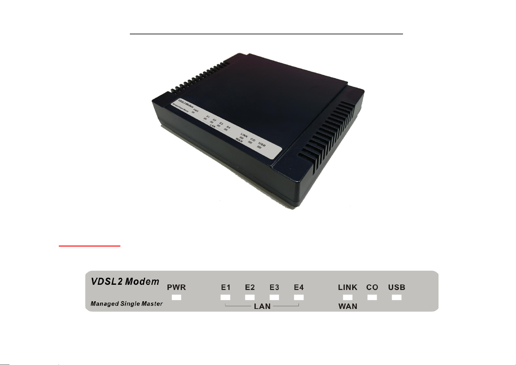
3.1 Front Panel
The figure shows the front panel. (Figure 3.1)

V700L Managed Single Master / Slave LAN Extender USER’S MANUAL Ver. B.2
14
Figure 3.1 Front Panel(V700L)
3.2 Front Indicators
The Modem has Seven LED indicators. The following Table shows the description. (Table 3-1)
Table 3-1 LED Indicators Description and Operation
LED
Color
Status
Descriptions
PWR
(Power LED)
Green
On(Steady)
Lights to indicate that modem had power good
Off
The device is not ready or has malfunctioned.
LED
Color
Status
Descriptions
E1 ~ E4
(Ethernet LED)
Green
On(Steady)
The device has a good Ethernet connection.
Blinking
The device is sending or receiving data.
Off
The LAN is not connected or has malfunctioned.

V700L Managed Single Master / Slave LAN Extender USER’S MANUAL Ver. B.2
15
LINK
(Line LED)
Green
On(Steady)
The Internet or network connection is up.
Fast Blinking
1. The Master device has detected a Slave device and ready to connect.
2. The device is sending or receiving data.
Off
The Internet or network connection is down.
USB
Green
On (Steady)
The device has a good USB dongle connection.
Off
The device is not ready or has malfunctioned.
CO
Green
On (Steady)
V700L config on Master mode.
Off
V700L config on Slave mode
Note:
It is normal for the connection between two V700L to take up to 3 minutes, due to V700L(Master) connect V700L(Slave) to establish
a link mechanism in auto-speed, with detects and calculates Master and Slave both PBO and PSD level, noise levels and other
arguments for getting a better connection.
3.3 Rear Panel
The following figure shows the rear panel. (Figure 3.2)

V700L Managed Single Master / Slave LAN Extender USER’S MANUAL Ver. B.2
16
Figure 3.3Rear Panel
And the table shows the description. (Table 3-2)
Table 3-2 Description of the modem rear connectors
Type
Connector
Description
Reset
Tact Switch Button
The reset buttons allows users to reboot the LAN V700L or load the default
settings.
Press and hold for 1-5 seconds: Reboot the V700L
Press over 5 seconds: Load the default settings
Power
DC Jack
External switching PowerAdapter: Input: AC 85~240Volts/50~60Hz.
Output: DC 12V/1A.
Line
RJ-11
For connecting to a Master/Slave device.
Type
Connector
Description
phone
RJ-11
For connecting to the POTS equipment or ISDN.
Ethernet
RJ-45
For connecting to an Ethernet equipped device.

V700L Managed Single Master / Slave LAN Extender USER’S MANUAL Ver. B.2
17
(E1-E4)
USB
USB2.0 Type A
For connecting to the USB dongle.
Before user installed power and device, please read and follow these essentials:
Use separate paths to route wiring for power and devices. If power wiring and device wiring paths must cross, make sure the
wires are perpendicular at the intersection point.
Note:
Do not run signal or communications wiring and power wiring through the same wire conduit. To avoid interference, wires with
different signal characteristics should be routed separately.
You can use the type of signal transmitted through a wire to determine which wires should be kept separate. The rule of thumb
is that wiring sharing similar electrical characteristics can be bundled together.
You should separate input wiring from output wiring.
We recommend that you mark all equipment in the wiring system.
Chapter 4.Configure the V700L via Web management menu

V700L Managed Single Master / Slave LAN Extender USER’S MANUAL Ver. B.2
18
The V700L provides a built-in HTML based management interface that allows configuration of the V700L via Internet
Browser. Best viewed using Chrome or Firefox browsers.
In order to use the web browser to configure the device, you may need to allow:
Web browser pop-up windows from your device. Web pop-up blocking is enabled by default in windows XP
SP2 or above.
Java Scripts. (Enabled by default)
Java permissions. (Enabled by default)
Launch your web browser and input the default IP address 192.168.16.249 (V700L) in the Web page.
Following section user can find default username and password.
4.1 BASIC Setup

V700L Managed Single Master / Slave LAN Extender USER’S MANUAL Ver. B.2
19
4.1.1 Login Webpage
The default username and password are “admin”.
Figure 4.1.1 Login Webpage
4.1.2 Display status
Table of contents
Popular Extender manuals by other brands


StarTech.com
StarTech.com F35023-USB-EXTENDER quick start guide

KVM-TEC
KVM-TEC USBflex Quick installation

Metra Electronics
Metra Electronics CS-HDBTPOE-100HDMI Extender over Cat5e/Cat6 user manual

Allnet
Allnet ALL-MC301P2WIRE-T Quick installation guide

MuxLab
MuxLab 500453 Quick installation guide

Atlona
Atlona AT-VGA100-SR user manual

EDOBE
EDOBE PM10 Quick installation

Network Technologies
Network Technologies XTENDEX ST-C5KVM Installation and operation manual

Bosch
Bosch LTC 8713 Series instruction manual

SolidView
SolidView ET0201-VF1 user manual

Alarm Lock
Alarm Lock Trilogy Networx AL-IME2-EXP installation instructions

gofanco
gofanco HDExt50 user guide