ELSAN Elektrik San VEMS 80-2-77 Troubleshooting guide


CONTENTS
CONTENTS…………………………………………………………..…. 1
1. GENERAL INFORMATION
1.1. Working Conditions ……………………………………………. 2
1.2. Transportation…………………………………………………….. 2
1.3. Storage………………………………………………………………… 3
1.4. Safety ……………………………………………….………………… 3
2. SETUP AND OPERATION
2.1. Setup ……………………………………………….…………………. 4
2.2. Insulation Resistance
…………………..……………………. 4
2.3. Vibration Generation Methods ………….………………. 5
2.3.1. Circular Method ……………………………………… 5
2.3.2. Single Direction Method ……...……………….. 5
2.4. Setting the Centrifugal Force…….……………….……. 5-6
2.5. First Start and Running…………….……………………….. 7
2.6. Rotation Direction ……………………………………………… 7-8
2.7. Final Check ………………………………………………………… 8
3. MAINTENANCE
3.1. Cleaning ……………………………………………………………… 9
3.2. Bearings ……………………..……………………………………… 9
3.2.1. Lubrication of Bearings ……….………….……… 9
3.2.2. Bearing Replacement
…….…………..……….... 11
3.3. Sealing Component ……………………...…………………… 11
4. FAULTS, REASONS, AND SOLVINGS
4.1. Tables of Troubleshooting .…………..…………………. 12-14
5. IDENTIFICATION AND MARKING
5.1. Vibration Motor Identification Plate ………………….. 15
5.2. Description of the sections on the plate …………… 15
6. COMPONENT OF VIBRATOR
6.1. Part Mapping With Section View .…………………..… 16
6.2. Bill of Material of Vibration Motor………………………… 17
7. OTHER INFORMATIONS
7.1. List of the Related Standards ………………………… 18
7.2. Figure – Table Indexes.……………………………………. 19
7.3. Authorized Services List …………………………..………. Back
cover

2
1. GENERAL INFORMATION
This operation and maintenance instruction includes low voltage, totally enclosed, cage rotor
asynchronous vibration motors manufactured in accordance with TS / EN norms.
This operation and maintenance instruction may not contain specific information about specific
applications and areas. In this case, the user must make appropriate protection arrangements during the
installation.
The following points should be considered for the matters not mentioned in this instruction,
1. Technical data given in the catalog and on the name plate
2. Information about the facility to use the vibration motor
3. Protective measures according to where the vibration motor will be used
Our vibration motors are 2 (TWO) YEAR WARRANTY. But; vibration motors not operated under
the conditions specified in this instruction, catalog, and name plate or not having the necessary
protection schemes in accordance with TS 10316 - EN 60204-1 are excluded from the warranty.
The structural changes to be made on the parts and repair and maintenance operations by
unauthorized personnel shall cause the vibration motor to be excluded from the warranty.
Bearings used in vibration motors are not guaranteed by the bearing manufacturer.
1.1. OPERATING CONDITIONS
Standard vibration motors, designed to operate at rated voltage and frequency (380 V, 50 Hz), -15 ÷
+40 °C ambient temperature and at sea level up to 1000 m.
Standard vibration motors within the scope of this operation and maintenance instruction are totally
enclosed, non-ventilated, and IP55 protection class. Measures should be taken for the vibration motors which
operating outdoors to protect against rain, snow, dust etc.
1.2. TRANSPORTING
80 and 90 frame motors have a lifting eye and bigger frames have lifting holes.

3
If the vibration motor has to be lifted together with additional loads, such as the chassis or the
driven machine; the additional loads must be lifted by their own system.
Vibration motors should never be placed on the fan covers and they should not be transported
and stored in this way.
1.3. STORAGE
The vibration motor must be checked visually if it is damaged or not during transportation. If the vibration
motor is to be stored for a long time, it must be kept a place which is clean, free of moisture and vibration.
1.4. SAFETY
Vibrating motors are connected to the power supply network and are rotated by magnetic induction. When
they transported, installed, used and maintained according to this operation and maintenance instruction, it
does not endanger any life
Vibration motors are industrial products. In this regard, the installation process must be carried
out by experienced and qualified personnel. Vibration motors are manufactured by taking
precautions against earth leakage and / or static electricity.
1. GENERAL INFORMATION

4
2. SETUP AND OPERATION_______________________
2.1. SETUP
During the stage of setting up the vibration motor, it should be taken into consideration that the
vibration motor can be easily reached during maintenance and repair times.
Vibration motors to work outside; The sun's rays should not come directly into the vibration
motor.
During normal operation, the vibration motor body may become too hot to touch. Therefore, the
vibration motor must not be touched.
2.2. INSULATION RESISTANCE
In case of vibration motors to be used after a long storage or waiting period, the insulation resistance
of the windings must be measured before commissioning. In the insulation resistance measurement process,
DC 500V is applied to the windings with insulation resistance measuring device (megaohmmeter) and the
resistance is read at the end of one minute.
Insulation resistance value measured at 25 ° C; 10 MΩ’ in a new vibration motor and 1 MΩ in a vibration
motor that has worked for a period of time.
If the measured insulation resistance value is below the limit values; winding must be cleaned and dried.
If the insulation resistance value is still low, the windings must be dried. Drying can be done in an oven or
with a heat gun. (heat gun temperature is 80 ° C)
Using DC voltage with the help of a transformer, drying can be achieved by applying a current not
exceeding 10% of the rated voltage and 20% of the rated current to the terminals U1 and V1 of the winding.
The insulation resistance must be checked again after the vibration motor has cooled down.
Do not touch the terminals during and after the measurement due to high voltage. After
measurement, the windings must be discharged immediately.

5
2. SETUP AND OPERATION
2.3. VIBRATION GENERATION METHOD
There are basically two vibration generation methods
2.3.1. Circular Method
In this method, vibration force is obtained in a circular direction in 360 ° clockwise and counterclockwise
using a vibration motor.
(Figure-1.a).
2.3.2. Single Direction Method
In this method, vibration forces are obtained in only one direction and sine curve by using two vibration
motors.(Figure-1.b).
a. Circular Method
b. Single Direction Method
Figure-1. Vibration generation methods
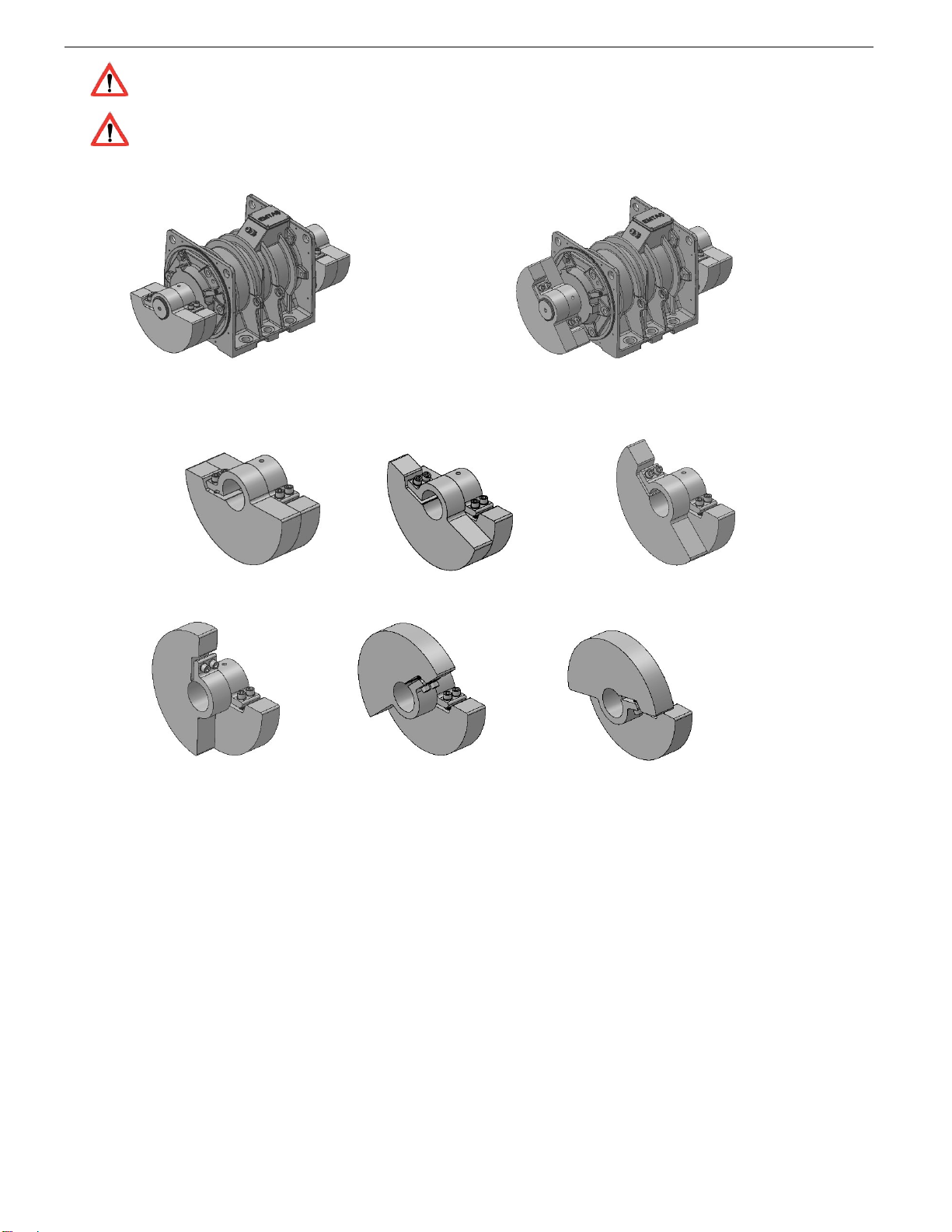
2.4. SETTING THE CENTRIFUGAL FORCE
Vibration motors are vibrated with eccentric hammers on both sides of the motor. A total of four eccentric
hammers are available in a vibration motor with two fixed and two adjustable.
Our vibration motors are shipped with the eccentric hammers set to step 3 (85%).
The vibration force is increased or decreased by changing the positions of the tuned hammers. As the
angle between the fixed and tuned hammers increases, the vibration force decreases.
To adjust the vibration force:
Remove the safety cover on both sides of the vibration motor.
Loosen the bolts on the adjustable (outside) hammers.
Rotate the adjustable hammers over the shaft to set them to the appropriate setting for your system.
Tighten the bolts on the adjustable hammers.
Install the safety cover on both sides of the vibration motor by checking that the sealing piece (oring)
between the vibration motor cover and the safety cover is properly installed.
6
2. SETUP AND OPERATION
The vibration motors must not be operated when the safety cover on both sides of the motor is
not installed.
The position of the hammers on both sides of the vibration motor, must be the same (parallel).
If the adjustment is made in a different direction, the position of the hammers on both sides is
not the same (parallel), the vibration motor shaft, the vibration motor mounting bolts and / or
the chassis to which the vibration motor is connected are damaged.
True False
Şekil-2. Setting the centrifugal force
1. Level (% 100) 2. Level (% 95) 3. Level (% 85)
4. Level (% 70)
5. Level (% 50)
6. Level (% 30)
Figure-3. Setting level of centrifugal force

7
2. SETUP AND OPERATION
2.5. FIRST START AND RUNNING
Our vibration motors are manufactured as standard only for direct starting. For this reason, our
vibration motors have 3 pole outputs in the terminal boxes.
The suitability of the network that will feed the vibration motor to the vibration motor plate
information must be checked and the supply cables should be selected according to these values. If the voltage
difference is greater than ± 5%, the vibration motor windings may be damaged.
Check the tightness of the nuts at the terminals. Loosely nuts cause the vibration motor to
malfunction.
The user has the responsibility to protect the vibration motor against overload. The vibration
motor must be connected to the mains via a thermal-magnetic switch which is capable of
protection against overcurrents. The current setting of the switch must not be more than 1.05
times the rated current of the vibration motor. Otherwise, the vibration motor is not covered by
the warranty.
Overload protection will only be possible by sensing excessive heat caused by overload and other
reasons (two phases, excessive ambient temperature or altitude, excessive starting stop, etc.). Install a
thermistor in the winding and to connect the terminals coming from the thermistor to the thermistor relay is
necessary for overload protection.
PTC thermistors are mounted as standard on 132, 160, 180 and 200 types of vibration motors and
Phase Protection Relay is given as free of charge. On request, our smaller vibration motors are supplied with
a thermistor and are supplied with a relay.
Vibration motors of type 132, 160, 180 and 200 should be used with thermistors. Otherwise, the
warranty terms will be invalid.
2.6. ROTATION DIRECTION
Our vibration motors are designed to operate in both directions. The rotation direction of the vibration
motor can be changed by replacing any two of the mains phases in the connection diagram L1, L2 and L3.

8
2. SETUP AND OPERATION
Şekil-4. Running Diagram
2.7. FINAL CHECK
If the mechanical and electrical connections of the vibration motor are technically
appropriate, it shall be appropriate to start the operation after the following checks.
1. The operating conditions must be compatible with the vibration motor plate. (3~380V %5, 50Hz
%2)
2. If the vibration motors are not used for a long time, the insulation resistance values must be sufficient.
3. All mechanical and electrical connections must be tight.
4. The moving and energized parts must be fully protected against touching.
5. The position of the hammers on both sides of the vibration motor must be the same (parallel).
When the vibration motor is being serviced, the vibration motor must not be connected to the
mains power (no power) and must be de-energized in the auxiliary circuits (heater etc.).

9
3. MAINTENANCE
3.1. CLEANING
Before and after work, dust accumulated on the body should be cleaned.
3.2. BEARINGS
Vibration motors are equipped with long-life bearings that can carry axial, radial and combined loads without
problems.
3.2.1. Lubrication of bearings
Vibration motors are equipped with lubricating nipples and oil drain channels. The grease type and lubrication
range are indicated on the vibration motor plate.
In order not to deteriorate the chemical and physical properties of the greases, different types
of greases should never be mixed. When lubricating, be sure to use the type of grease indicated
on the vibration motor plate.
In the case of initial lubrication, no grease should be expected from the discharge duct. After
several lubrication, dirty grease will appear in the discharge duct.
For re-lubricating bearings;
Remove the grease drain plug
Clean the dirty grease on the drain and make sure the drain is open.
Clean the grease nipple and the tip of the grease gun.
Pump up to half the grease of the quantity indicated in the table on page -11.
Operate the vibration motor at full speed for several minutes.
When the vibration motor stops, pump the remaining grease into the bearing.
Install the grease drain plug.
Lubrication hours (operating hours) and grease quantities (gr) for vibration motors with lubricating
nipples are given in Table-1.

10
3. MAINTENANCE
VIBRATION MOTOR / BALL- ROLLER (63/64 SERIES - NJ TYPE)
BEARINGS
VIBRATION MOTOR
TYPE 2 Pole 4 Pole 6 Pole 10 Pole
VEMS 80-2-77 0,7 kW 2.000 4 - - -
VEMS 80-4-47 0,37 kW - 3.300 5 - -
VEMS 90-2-116 1,7 kW 1.750 7 - - -
VEMS 90-4-117 0,55 kW - 2.800 10
- -
VEMS 90-4-159 0,75 kW - - -
VEMS 90-4-181 1,1 kW - 2.700 12
- -
VEMS 90-6-108 1,1 kW - - 3.500
10
-
VEMS 100-4-242
1,5 kW - 2.250 18
- -
VEMS 100-4-282
2,0 kW - - -
VEMS 100-10-80
0,2 kW - - - 5.000 1
0
VEMS 112-2-210
2 kW 1.150 15
- - -
VEMS 112-4-327
2,2 kW - 2.250 15
- -
VEMS 112-4-413
2,4 kW - 2.100 26
- -
VEMS 112-4-456
3,2 kW - - -
VEMS 112-6-145
1,5 kW - - 2.900
15
-
VEMS 112-6-202
2 kW - - -
VEMS 132-2-530
4 kW 900 22
- - -
VEMS 132-4-551
3,5 kW - 2.000 34
- -
VEMS 132-6-416
3,2 kW - - 2.800
23
-
VEMS 160-4-736
5,8 kW - 1.700 44
- -
VEMS 160-6-583
4 kW - - 2.500
38 -
VEMS 160-6-705
4,5 kW - - -
VEMS 160-6-881
7,5 kW - - 2.400
54
-
VEMS 160-6-981
8,0 kW - - -
VEMS 180-6-130
9,2 kW - - 2.300
78
-
VEMS 180-6-136
11 kW - - -
VEMS 200-6-137
11,2 kW - - 2.300
78
-
VEMS 200-6-153
12,5 kW - - 2.100
96
-
VEMS 200-6-181
15 kW - - -
Table-1. Lubrication Interval of Bearings
[Operating Hours] and Grease Amounts [gr]
The values in the table are calculated for the bearing temperature of 100 ° C.

11
3. MAINTENANCE
Refer to the vibration motor plate for current bearing and lubrication information.
3.2.2. Bearing Replacement
Dismantling of bearings:
Roller bearings: The inner ring must be heated with flame and removed by means of a puller. If not,
the inner ring should be turned and refuted.
Ball Bearings: After the inner ring has been heated slightly, it should be removed by using puller.
Never use hammer.
Mounting of bearings:
The inner rings of the ball bearings and roller bearings must be heated to an average temperature of
80 ° C in the induction heater or in the oil bath (open bearings only). The heated bearing can be easily
installed on the shaft.
When the bearings are mounted on the shaft, impacts from the outer ring must not be applied. Instead,
light impacts can be applied to the ring-type tools and the bearing inner ring made of the shaft diameter.
When attaching the vibration motor bearing covers, suitable tools should be used with the cover
diameter.
To replace the bearings, the rotor and shaft assembly must be removed. During this time, the
stator windings must be observed and the windings must be protected.
A bearing must not be unpacked until it is installed. They must be protected from dirty and dusty
environments.
3.3. SEALING COMPONENTS
The sealing components (eg oring) between the vibration motor cover and the housing must be
correctly seated in the housing. Damage must be prevented when adjusting the vibration force.
Oil seals with 112 and 132 types and 160 types of vibration motors (excluding 7,5 kW - 1000 1 /
min) must be fitted with suitable tools.
The sealing components can be lubricated with machine oil before assembly. The sealing components
must be installed in the correct axis to the mounting locations. When they are not fitted on the right axis, they
cause excessive friction.

12
4. TROUBLESHOOTING
4.1. MALFUNCTION OF VIBRATION MOTOR
FAULTS
REASONS SOLVINGS
The vibration motor
does not rotate
under voltage,
there is no sound
from the vibration
motor.
Fault in control circuit
(panel).
Check terminal ends, if there
is no power, check the board
for faults.
There is no energy in at
least two phases. In the
control with the test
light, energy is seen.
However, there is no
value in the voltmeter.
Check fuses, cables, and the
relevant screws and
terminals (Deactivate the
vibration motor during
replacement of defective
fuses).
The thermal relay or
thermistor phase
protection relay has
deactivated the
vibration motor.
Check the thermic relay,
thermistor and thermistor
relay
The ground mounting
bolts are loose.
Tighten the bolts.
The vibration motor
does not rotate
under voltage and
has excessive
magnetic sound.
There is no energy in
one of the phases.
Find the non-energized
phase, replace the relevant
fuse.
The counter torque is
too big.
Check and rearrange the
system, run the vibration
motor with no load.
The vibration motor
is not working
under load. But the
magnetic sound is
normal.
The mains voltage is
low.
Measure the voltage.
The vibration motor
is
overheating when
running without
load.
Mains voltage is high.
Measure the mains voltage
and the no load current.
Table-2 - Troubleshooting

13
4. TROUBLESHOOTING
4.1. MALFUNCTION OF VIBRATION MOTOR
FAULTS
REASONS SOLVINGS
The vibration
motor works fine
while unloaded.
The speed of the
vibration motor is
extremely low
under load.
One of the phases is die
after the vibration motor
has started running.
Control the voltage on each
phase
Rotor short-circuit bars
are broken, ampermeter
reads irregular currents.
Contact an authorized service
center.
The current and
temperature
values exceed
the normal
values when the
vibration motor is
running.
Vibration motor
overloaded.
Check the current.
The vibration
motor is warm
when it is
running without
load.
Mains voltage is
high.
Measure the mains voltage
and the no-load current.
The vibration
motor stops for
a certain
period of time.
Vibration motor
overloaded.
Do not overload the motor.
The thermic relay is
not correctly set or
thermistor device
active
Correct the thermic relay
setting.
The vibration
motor is
running
extremely loud.
The chassis mounting
bolts are loose. Tighten the bolts.
The welded assembly
of the machine are
broken.
Repair the assembly
connections.
The eccentric hammer
adjustment of the
vibration motor is
distorted.
Adjust the eccentric
hammers of the vibration
motor so that they are at
the same angle on both
sides.
Table-2 - Troubleshooting
14
4. TROUBLESHOOTING
4.1. MALFUNCTION OF VIBRATION MOTOR
FAULTS
REASONS SOLVINGS
The phase
currents are
extremely
different.
Phase voltages are
different. Check the voltage.
The mains voltage or
the windings are
disconnected. Check mains voltage and
windings.
Stator winding
touches the ground.
There is a short
circuit in the
stator windings.
The bearing is
deteriorating
very quickly.
Bearing overloading.
Check the system.
Eliminate excessive radial
and axial forces, if any.
Lubrication problem.
Take care to lubricate.
The eccentric hammer
adjustment of the
vibration motor is
distorted.
Adjust the eccentric hammers of
the vibration motor so that they
are at the same angle on both
sides.
The bearings
have
overheated
after a long
period of
operation.
Grease
lubricated
bearings have
a whistling
sound
.
No oil in the
bearing.
Lubricate the bearing,
replace if necessary.
Sealing of the
bearing covers (such
as seals and seals)
is damaged.
Replace the bearing,
contact service if
necessary.
Bearing is running
dry
.
Take care to lubricate.
Error in the bearing
cage.
Replace the bearing.
Table-2 - Troubleshooting
15
5. IDENTIFICATION AND MARKING
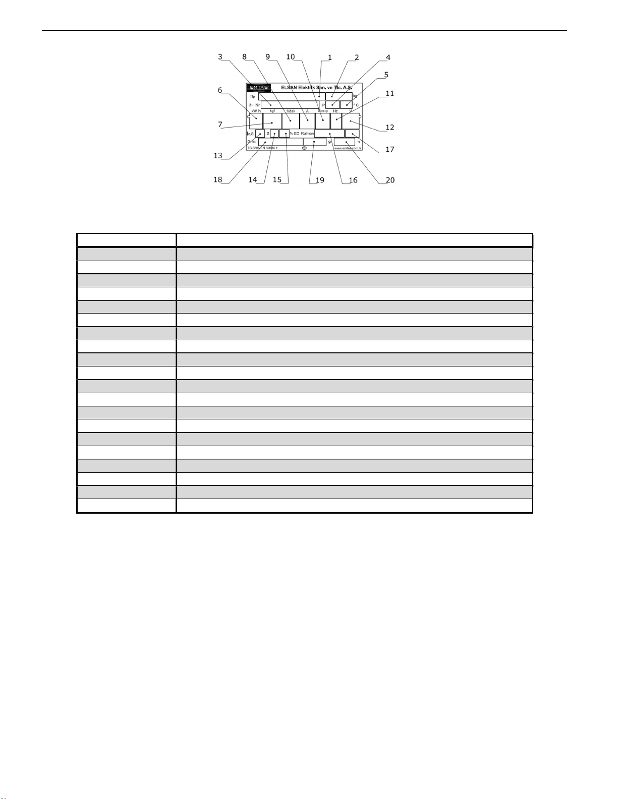
5.1. IDENTIFICATION AND MARKING
Figure 5- Vibration Motor Name Plate
5.2. DESCRIPTIONS OF THE SECTIONS ON THE NAME PLATE
Number Definition
1 Vibration Motor Type
2 Vibration Motor Weight, [kg]
3 Serial Number
4 Ingress Progress Class
5 Operating Environment Temperature [°C]
6 Input Power, [kW]
7 Centrifugal Force, [kgf]
8 Rated Speed, [1/dak]
9 Rated Current, [A]
10 Power Factor, Cos φ
11 Frequency, [Hz]
12 Voltage, [V]
13 Winding Insulation Class
14 Duty
15 Power Factor, [%]
16 Bearing Data
17 Bearing Data
18 Type of Grease
19 Grease Quantity for Relubrication , [gr]
20 Interval of Lubrication [running time (h)]
Table-3. Name Plate Descriptions of Vibration Motor

16
6.COMPONENT OF VIBRATOR______________________________________________________
6.1. PART MAPING WITH SECTION VIEW
Figure
-
6
.
Part mapping of vibration motor

17
6.COMPONENT OF VIBRATOR______________________________________________________
6.2. PART LIST OF VIBRATION MOTOR
PART NUMBER PART NAME
1 FRAME
2 STATOR PACK
3 STATOR WINDING
4 SHAFT
5 ROTOR PACK
6 SOLID SHAFT RING FOR BEARING
7 BEARING
8 SHIELD
9 OUTER BEARING CAP*
10 SETSCREW BOLT**
11 PERMANENT HAMMER
12 SETTING HAMMER
13 HAMMER CLAMPING BOLT
14 SHAFT RING FOR HAMMER
15 LUBRICATION FITTING
16 O-RING (SEALING COMPONENT)
17 SAFETY COVER
18 TERMINAL BOARD
19 TERMINAL BOX COVER
20 CABLE GLAND
Table-4. Part list of vibration motor
* Outer ball cap (except 7.5 kW - 1000 1 / min) for 160 types of vibration motors with 112/2 and 132 types;
There are 100,112 and 160 types and 180 and 200 types of vibration motors with inner ball cap.
** Setscrew mounting should use a removable screw adhesive. (Example: Loctite 243)

18
7. OTHER INFORMATION
7.1. LIST OF RELATED STANDARDS
DOCUMENT NAME OF DOCUMENT
TS EN 60034-1 Rated values and performance
TS EN 60034-2-1 Measurement methods of efficiency and loss
TS 3209
EN 60034-5 Ingress Progress Classification (IP Classification)
TS 3210
EN 60034-6 Cooling Method (IC Classification)
TS 3211
EN 60034-7
Construction and assembly arrangements
(IM Classification)
TS EN 60034-8 Markings of the terminals and direction of rotation
TS EN 60034-9 Noise level limits
TS 6848
EN 60034-12 Starting Performance
TS EN 60034-14 Vibration limits and measurement
TS EN 60034-15 Voltage resistance in AC machines
TS EN 60034-18-1 Insulation and thermal classification
TS EN 50347 Identification of Induction Motor
Table-5. List of related standarts
7.
OTHER INFORMATION
7.2. INDEX OF FIGURE AND TABLE
FIGURE NAME OF FIGURE SECTION PAGE
1 Vibration generation methods 2.3 6
2 Setting the centrifugal force 2.4 6
3 Setting level of centrifugal force 2.4 7
4 Running Diagram 2.6 9
5 Name Plate of Vibration Motor 5.1 18
6 Part Maping of Vibration Motor 6.1 19
Table.6. Index of Figure
TABLE NAME OF TABLE SECTION PAGE
1 Lubrication Interval of Bearing 3.2.1 10
2 Troubleshooting 4.1 12-14
3 Name Plate Descriptions of Vibration Motor 5.2 15
4 Part list of Vibration Motor 6.2 17
5 Related Standarts 7.1 18
6 Index of Figure 7.2 19
7 Index of Table 7.2 19
8 List of Authorized Services 7.3 Back Cover
Table.7. Index of Table
This manual suits for next models
28
Table of contents
Popular Engine manuals by other brands


MVVS
MVVS 175 NP 3012 operating instructions

Doosan
Doosan DE12T Operation & maintenance manual

Mitsubishi
Mitsubishi 4G93-SOHC Workshop manual

BRP
BRP Rotax 4-TEC 150 Operator's manual

Toshiba
Toshiba Low Voltage Motors VR Series Brochure & specs

Stobag
Stobag MOVENO DWIR-E Installation and use instructions and warnings