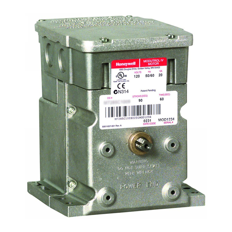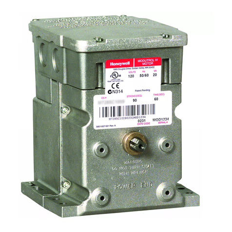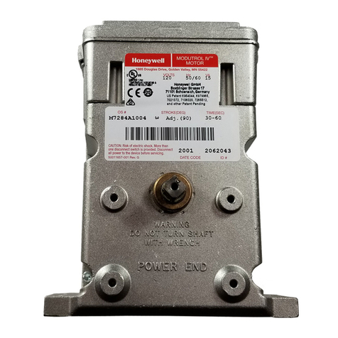
WHEN INSTALLING THIS PRODUCT…
1. Read these instructions carefully. Failure to follow
them could damage the product or cause a hazardous
condition.
2. Check the ratings given in the instructions and on
the product to make sure the product is suitable for your
application.
3. Installer must be a trained, experienced service
technician.
4. After installation is complete, check out product
operation as provided in these instructions.
CAUTION
1. Disconnect power supply before beginning
installationtopreventelectricshockorequip-
ment damage. More than one disconnect may
berequired to be openedto remove allpower.
2. Donotattempttoturnthemotorshaftbyhand
or with a wrench. Damage to the gear train
will result.
LOCATION
Install the motor in any location except where acid
fumesorother deterioratingvaporsmightattackthemetal
parts,orinatmospheresofescapinggasorotherexplosive
vapors. The M7484A is rated for temperatures between
32°F to150°F. If located outdoors, use weatherproofing
kit; see Accessories section.
Allow enough clearance for installing accessories and
servicing the motor when selecting a location. See Fig. 1.
MOUNTING
Always install the motor with the crankshaft horizon-
tal. Mounting flanges extending from the bottom of the
motor housing are drilled for 1/4 in. machine screws or
bolts.
The M7484A is shipped from the factory in the closed
position,whichisthelimitofcounterclockwiserotationas
viewed from the power end of the motor, see Fig. 2.
Fig. 2—Motor shaft position at rotational limits
as viewed from the power end of the motor.
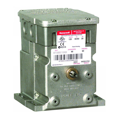
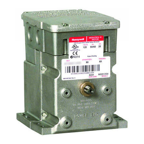
M7484A
INSTALLATION
4
Installation
!
INSTALLING LINKAGES
A crank arm is not included with the motor.
In general, check the following points of operation
when installing a motor and linkage:
1. Adjust linkages for valves and louver type dampers
adjust so that the damper or valve moves through only the
maximumrequireddistancewhenthemotormovesthrough
its full stroke.
2. Stop the motor at the end of its stroke by using
internaltravellimitswitch; do not stall themotorbyusing
the damper or valve. CAUTION: The motor will be
damaged if it is not permitted to complete its full stroke.
3. For any installation, do not exceed the motor rat-
ings.
WIRING
Disconnect power supply before wiring to prevent
electrical shock or equipment damage. More than one
disconnect may be required to be opened to remove all
power.
1. Be sure all wiring agrees with applicable codes,
ordinances, and regulations.
2. Make sure that the voltage and frequency stamped
onthemotorcorrespondtothecharacteristicsofthepower
supply.
3. See Fig. 3 for the internal schematics and terminal
connections to the M7484A motor.
4. Use the recommended wire size and type:
• Terminals 1, 2, and 3 require No. 18 wire insulated
for voltages and temperatures encountered in the
application. Suggested conductor types include
TW[60C], THW [75C] and THHN [90C].
• Terminals G, T, and Y for the motor position indi-
cation circuit require a shielded three conductor
cablethatisUL listedfortemperaturesandvoltages
encountered in the application. Suggested cables
include Belden 9365 rated for 300V, 105°C or
Belden 8770 rated for 300V, 60°C.
5. Do not connect the shield to anything at the motor
end; tape the shield to avoid any unintended contact with
the motor housing. At the BCS 7700 end, ground the
shield to the control panel with as short as practical lead
wire length.
6. Do not route the feedback potentiometer circuit
leadwires in conduit with line voltage circuits.
7. Avoid routing the feedback potentiometer circuit
leadwires close to the ignition transformer leadwires.
8. Feedback potentiometer (low voltage) circuit lead-
wires can be routed outside of conduit if properly sup-
ported and protected from damage.
9. Maximum feedback potentiometer circuit leadwire
length of 100 feet.
10. Complete the required checkout as indicated in this
specification and return the system to normal operation.
VERTICAL
REFERENCE
FULL
CLOSED
FULL
OPEN
90 DEGREE STROKE E2390
90°
45°
