Elsner 70387 Guide

Installation and Adjustment
Item number 70387
EN
Elsner Elektronik GmbH Control and AutomationTechnology
Sohlengrund 16
75395 Ostelsheim Phone +49 (0) 70 33 / 30 945-0 info@elsner-elektronik.de
Germany Fax +49 (0) 70 33 / 30 945-20 www.elsner-elektronik.de
Vari KNX GPS
GPS Receiver
Technical support: +49 (0) 70 33 / 30 945-250

1 Contents
Elsner Elektronik GmbH • Sohlengrund 16 • 75395 Ostelsheim • Germany
GPS Receiver Vari KNX GPS • from ETS programme version 1.0
Status:22.08.2017 • Errors excepted. Subject to technical changes.
1. Description ........................................................................................... 3
1.0.1. Scope of delivery .......................................................................................... 3
1.1. Technical specification ............................................................................................. 3
2. Installation and start-up ....................................................................... 4
2.1. Installation notes ...................................................................................................... 4
2.2. Installation location .................................................................................................. 4
2.3. Device design ........................................................................................................... 6
2.4. Installing the device ................................................................................................. 6
2.4.1. Preparation for installation .......................................................................... 6
2.4.2. Fitting the lower part of the housing with mounting ................................. 7
2.4.3. Connection .................................................................................................... 9
2.4.4. Completing the installation .......................................................................... 9
3. Addressing the device .......................................................................... 9
4. Maintenance ....................................................................................... 10
5. Transfer protocol ............................................................................... 11
5.1. List of all communication objects ......................................................................... 11
6. Parameter setting .............................................................................. 19
6.1. Behaviour on power failure/ restoration of power .............................................. 19
6.1.1. Malfunction objects .................................................................................... 19
6.1.2. General settings .......................................................................................... 19
6.2. GPS .......................................................................................................................... 19
6.3. Location ................................................................................................................... 20
6.4. Sun position ............................................................................................................ 22
6.5. Weekly timer ........................................................................................................... 23
6.5.1. Weekly timer period 1-24 ........................................................................... 23
6.6. Calendar timer ........................................................................................................ 24
6.6.1. Calendar clock Period 1-4 ........................................................................... 25
2 Clarification of signs
This manual is amended periodically and will be brought into line with new software
releases. The change status (software version and date) can be found in the contents footer.
If you have a device with a later software version, please check
www.elsner-elektronik.de in the menu area "Service" to find out whether a more up-to-
date version of the manual is available.
Clarification of signs used in this manual
Installation, inspection, commissioning and troubleshooting of the device
must only be carried out by a competent electrician.
Safety advice.
Safety advice for working on electrical connections, components,
etc.
DANGER! ... indicates an immediately hazardous situation which will lead to
death or severe injuries if it is not avoided.
WARNING! ... indicates a potentially hazardous situation which may lead to
death or severe injuries if it is not avoided.
CAUTION! ... indicates a potentially hazardous situation which may lead to
trivial or minor injuries if it is not avoided.
ATTENTION! ... indicates a situation which may lead to damage to property if it is
not avoided.
ETS In the ETS tables, the parameter default settings are marked by
underlining.

3 Description
GPS Receiver Vari KNX GPS • Status: 22.08.2017 • Errors excepted. Subject to technical changes.
1. Description
The GPS Receiver Vari KNX GPS for the KNX building system receives the GPS sig-
nal for time and location and uses it to compute the position of the sun (azimuth and
elevation).
The compact housing of the Vari KNX GPS accommodates the receiver, evaluation
circuits and bus-coupling electronics.
Functions:
•GPS receiver, outputting the current time and location coordinates. The GPS
Receiver Vari KNX GPS also computes the position of the sun (azimuth and
elevation)
•Weekly and calendar time switch: All time switching outputs can be used
as communication objects.
The weekly time switch has 24 periods. Each period can be configured either
as an output or as an input. If the period is an output, then the switching time
is set per parameter or per communication object.
The calendar time switch has 4 periods. Two on/off switching operations,
which are executed daily, can be set for each period
Configuration is made using the KNX software ETS. The product file can be down-
loaded from the Elsner Elektronik website on www.elsner-elektronik.de in the “Ser-
vice” menu.
1.0.1. Scope of delivery
• Receiver
• Stainless steel installation band for pole installation
• 4×50 mm stainless steel roundhead screws and 6×30 mm dowels for wall
mounting. Use fixing materials that are suitable for the base!
1.1. Technical specification
Housing Plastic
Colour White / Translucent
Assembly Surface mount
Protection category IP 44
Dimensions approx. 65 × 80 × 30 (W × H × D, mm)
Weight approx. 60 g
Ambient temperature Operation -30…+50°C, Storage -30…+70°C
Operating voltage KNX bus voltage
Bus current max. 20 mA
Data output KNX +/- bus connector terminal
BCU type Integrated microcontroller
PEI type 0

4 Installation and start-up
GPS Receiver Vari KNX GPS • Status: 22.08.2017 • Errors excepted. Subject to technical changes.
The product conforms with the provisions of EU directives.
2. Installation and start-up
2.1. Installation notes
Installation, testing, operational start-up and troubleshooting should
only be performed by an electrician.
CAUTION!
Live voltage!
There are unprotected live components inside the device.
• National legal regulations are to be followed.
• Ensure that all lines to be assembled are free of voltage and take
precautions against accidental switching on.
• Do not use the device if it is damaged.
• Take the device or system out of service and secure it against
unintentional use, if it can be assumed, that risk-free operation is no
longer guaranteed.
The device is only to be used for its intended purpose. Any improper modification or
failure to follow the operating instructions voids any and all warranty and guarantee
claims.
After unpacking the device, check it immediately for possible mechanical damage. If it
has been damaged in transport, inform the supplier immediately.
The device may only be used as a fixed-site installation; that means only when assem-
bled and after conclusion of all installation and operational start-up tasks and only in
the surroundings designated for it.
Elsner Elektronik is not liable for any changes in norms and standards which may occur
after publication of these operating instructions.
2.2. Installation location
The GPS Receiver Vari KNX GPS must be installed outside.
Group addresses max. 2000
Assignments max. 2000
Communication objects: 150
5 Installation and start-up
GPS Receiver Vari KNX GPS • Status: 22.08.2017 • Errors excepted. Subject to technical changes.
Magnetic fields, transmitters and interference fields from electrical consumers (e.g. flu-
orescent lamps, neon signs, switch mode power supplies etc.) can block or interfere
with the reception of the GPS signal.
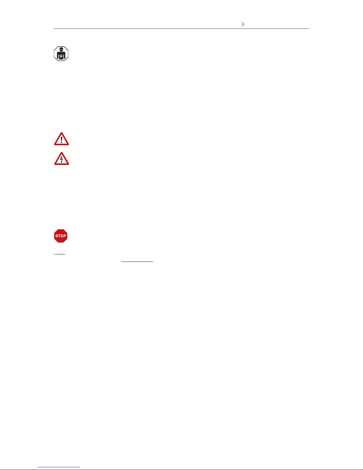
Fig. 1
The device must be attached to a vertical wall
(or a pole).
wall
or
pole
90°
Fig. 2
The device must be mounted in the horizontal
(transverse) direction.
Horizontal

6 Installation and start-up
GPS Receiver Vari KNX GPS • Status: 22.08.2017 • Errors excepted. Subject to technical changes.
2.3. Device design
2.4. Installing the device
ATTENTION!
Even a few drops of water can damage the device electronics.
• Do not open the device if water (e.g. rain) can get into it.
2.4.1. Preparation for installation
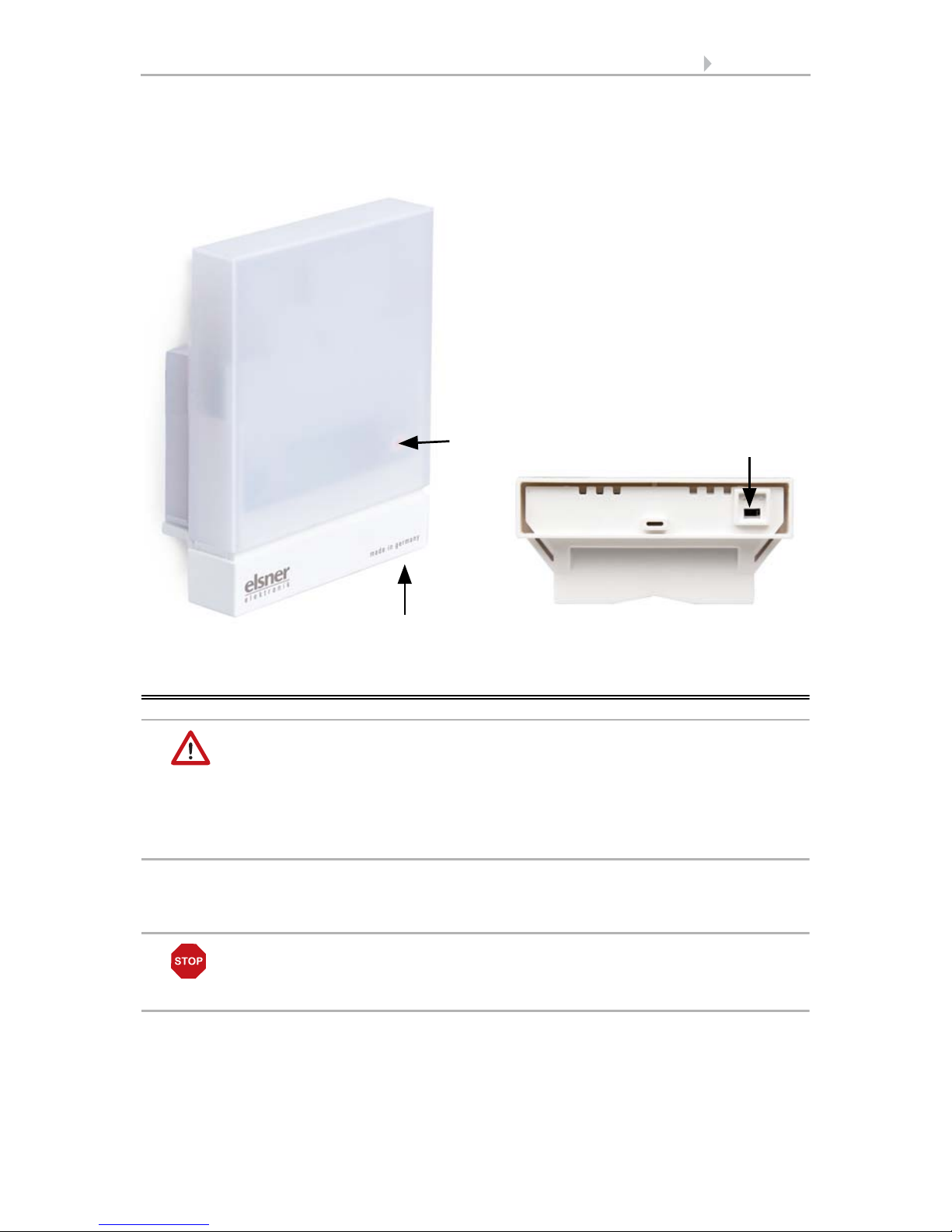
2
Fig. 3
1 Semi-transparent cover
(GPS receiver below)
2 Position of the Signal LED (un-
der the cover). LED is freely con-
trolled via two objects
3 Position of the programming
LED (under the cover)
4 Lower part of housing
5 Programming key on the bottom
of the housing (recessed), see
Device design, page 6
6 Wall/Pole holder
3
6
5
4
1
Fig. 4
The cover and lower part of the housing are
connected together. Pull both parts apart in a
straight line.
7 Installation and start-up
GPS Receiver Vari KNX GPS • Status: 22.08.2017 • Errors excepted. Subject to technical changes.
2.4.2. Fitting the lower part of the housing with mounting
Now, first of all, assemble the lower part of the housing with the integrated mounting
for wall or pole installation.
Wall installation
Use fixing materials (dowels, screws) that are suitable for the base.
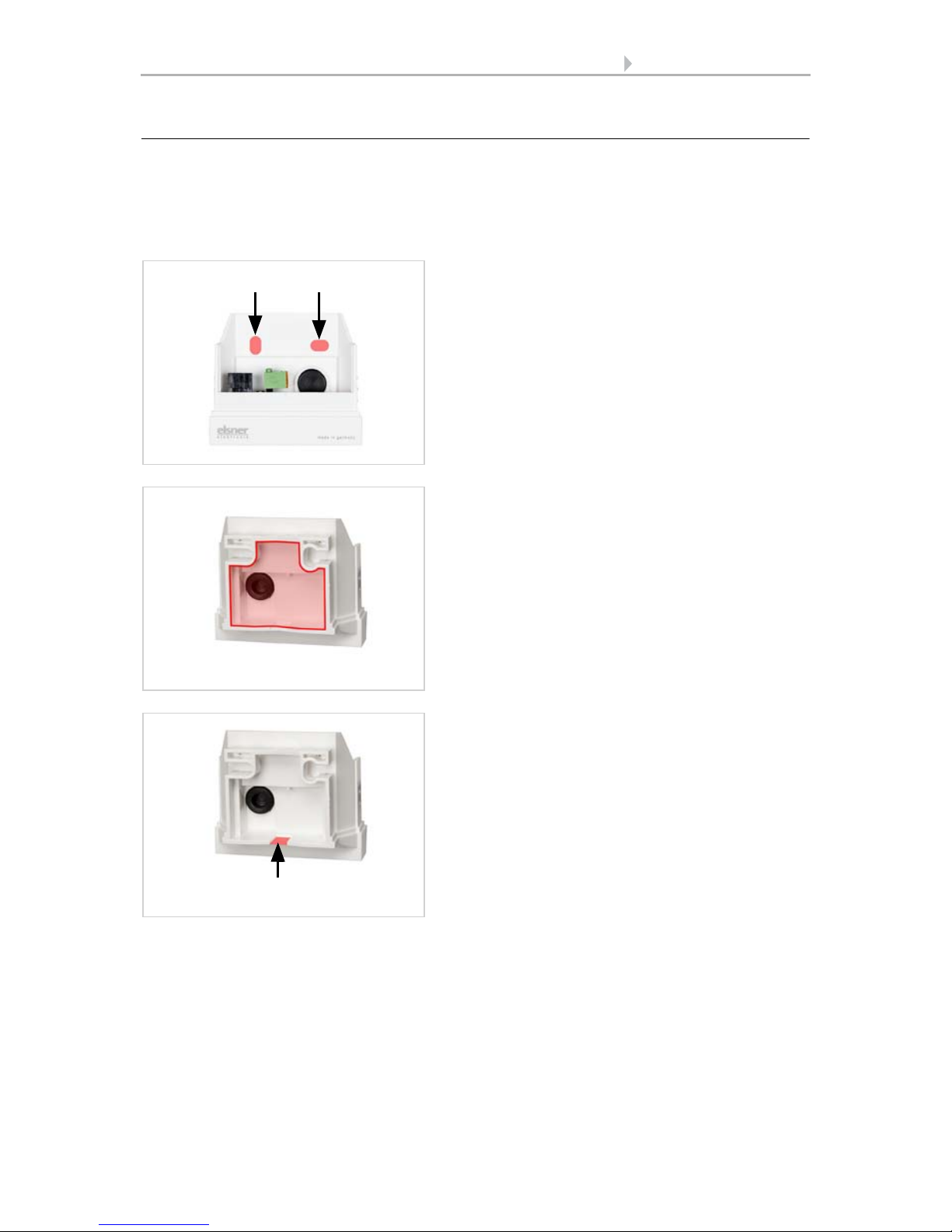
Fig. 5
The device is installed with two screws. Break
off the two longitudinal holes in the housing.
Longitudinal holes
Fig. 6 a+b
a) If the power lead is to be hidden when in-
stalled, it must emerge from the wall in
the vicinity of the rear of the housing
(marked area).
b) If the power lead is to be surface-mount-
ed, the cable guide is broken off. The lead
is then fed into the device from the bot-
tom of the housing.
Cable guide
8 Installation and start-up
GPS Receiver Vari KNX GPS • Status: 22.08.2017 • Errors excepted. Subject to technical changes.
Drilling plan
ATTENTION! The print out of the data sheet doesn‘t have original size!
A separate, dimensionally correct drilling plan is included ex works and this can be
used as a template.
Pole installation
The device is installed on the pole with the enclosed stainless steel mounting band.
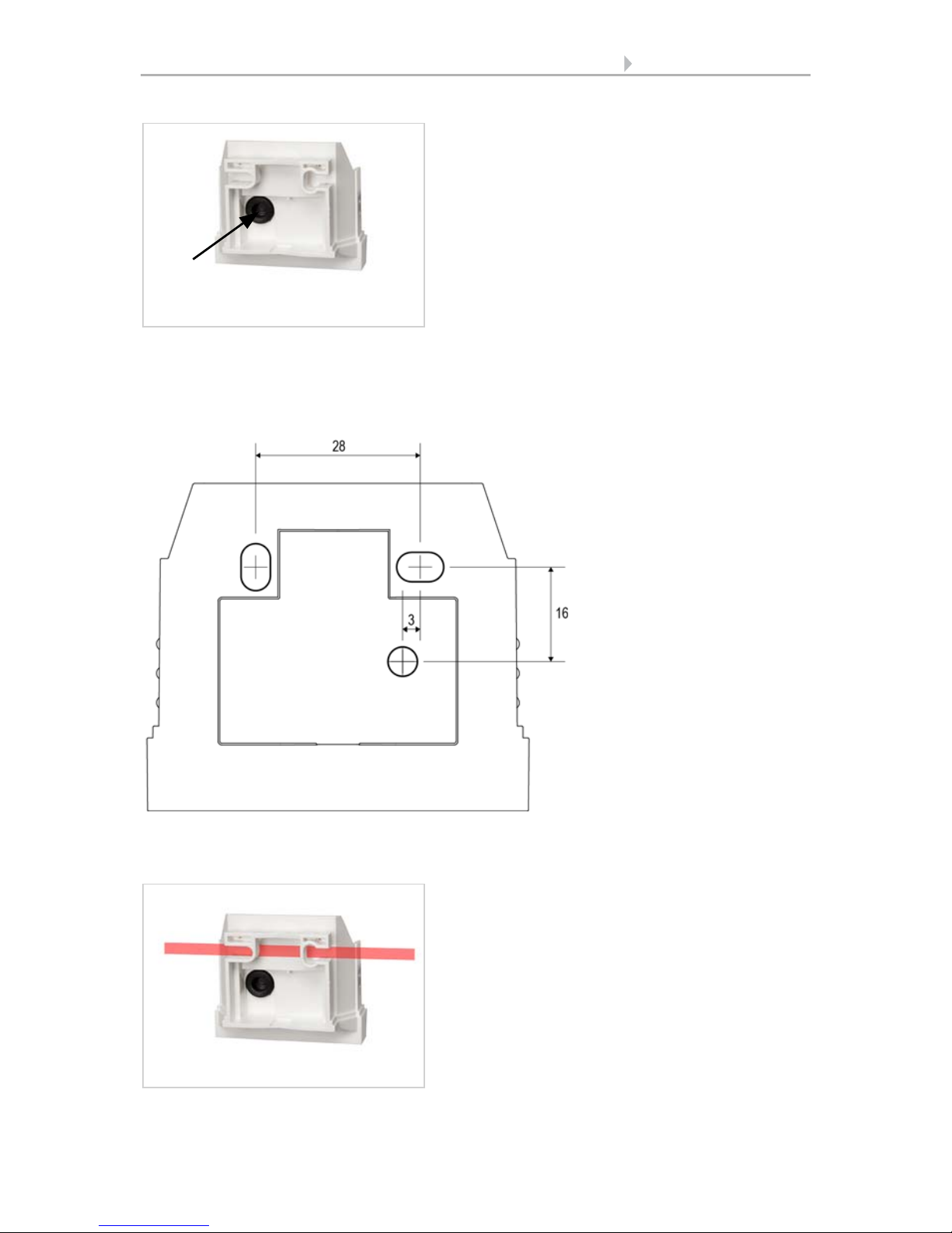
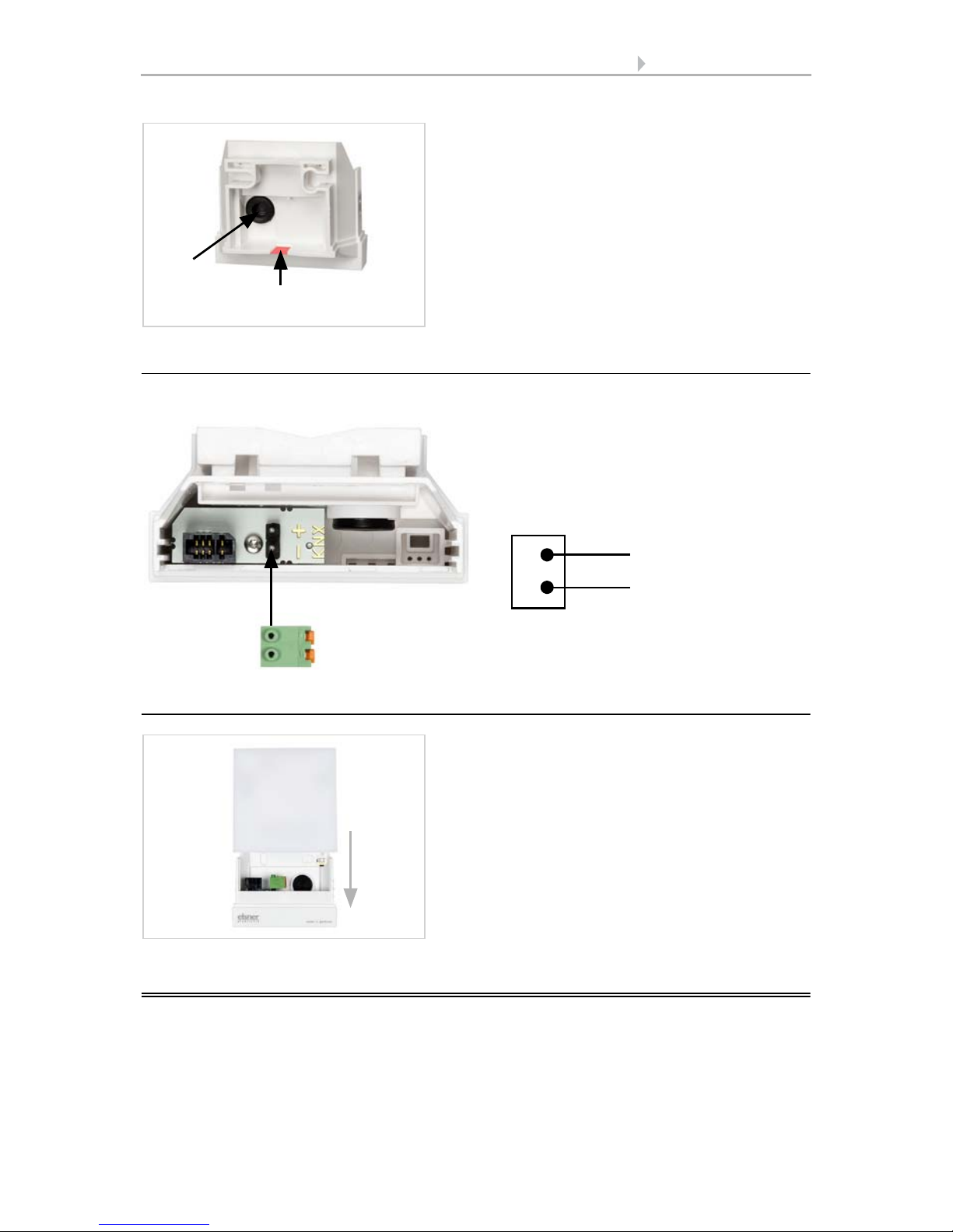
Fig. 7
Feed the power lead through the rubber gas-
ket.
Rubber
gasket
Fig. 8
Dimensions in mm. Varia-
tions are possible for tech-
nical reasons
A/B2× longitudinal holes
8 mm × 5 mm
C Position of the cable
outlet (rubber gasket)
in the housing
AB
C
Fig. 9
Feed the mounting band through the eyelets
in the lower part of the housing.
9 Addressing the device
GPS Receiver Vari KNX GPS • Status: 22.08.2017 • Errors excepted. Subject to technical changes.
2.4.3. Connection
The connector is in the lower part of the housing.
2.4.4. Completing the installation
3. Addressing the device
The device is delivered ex works with the bus address 15.15.250. You can program a
different address in the ETS by overwriting the address 15.15.250 or by teaching the
device via the programming button.
Fig. 10
Break the cable guide off.
Feed the power lead through the rubber gas-
ket.
Rubber
gasket Cable guide
Fig. 11
Connect the device to the KNX bus via
the pluggable terminal (+|-).
-
+
-
+
KNX
Fig. 12
Put the cover on the lower part. This also
makes the plug-in connection between the
board in the cover and the socket in the lower
part.
10 Maintenance
GPS Receiver Vari KNX GPS • Status: 22.08.2017 • Errors excepted. Subject to technical changes.
The programming button can be reached through the opening on the underside of the
housing; it is recessed by approx. 8 mm. Use a thin object to reach the button, e.g. a
1.5 mm² wire.
4. Maintenance
WARNING!
Risk of injury due to automatically moved components!
The automatic control may cause parts of the system to start up and
pose a danger to humans.
• Always disconnect the system from the mains power before
maintenance or cleaning.
The device should be regularly checked twice a year for soiling and cleaned if required.
If there is major soiling, the function of the receiver may be limited.
ATTENTION
The device may be damaged if water penetrates the housing.
• Do not clean with high pressure cleaners or steam jets.
Fig. 13 a+b
1 Programming LED (under the semi-
transparent cover)
2 Programming button for teaching
the device
12
2Housing from below

11 Transfer protocol
GPS Receiver Vari KNX GPS • Status: 22.08.2017 • Errors excepted. Subject to technical changes.
5. Transfer protocol
Units:
Azimuth and elevation in degrees
5.1. List of all communication objects
Abbreviation flags:
C Communication
R Read
WWrite
T Transfer
UUpdate
No. Text Func-
tion
Flags DPT type Size
1 Software version Output R-CT [217.1] DPT_Ver-
sion
2 bytes
21 Signal LED object 1s cycle Input -WC- [1.1] DPT_Switch 1 bit
22 Signal LED object 4s cycle Input -WC- [1.1] DPT_Switch 1 bit
24 GPS malfunction (0 : OK | 1: NOK) Output R-CT [1.2] DPT_Bool 1 bit
25 Date / time Output RWCT [19.1] DPT_Date-
Time
8 bytes
26 Date Output RWCT [11.1] DPT_Date 3 bytes
27 Time Output RWCT [10.1] DPT_-
TimeOfDay
3 bytes
28 Date and time query Input -WC- [1.017] DPT_Trig-
ger
1 bit
30 Location: Northern latitude [°] Output R-CT [14.7] DPT_Val-
ue_AngleDeg
4 bytes
31 Location: Eastern longitude [°] Output R-CT [14.7] DPT_Val-
ue_AngleDeg
4 bytes
261 Sun position: Azimuth Output R-CT [14.7] DPT_Val-
ue_AngleDeg
4 bytes
262 Sun position: Elevation Output R-CT [14.7] DPT_Val-
ue_AngleDeg
4 bytes
263 Sun position: Azimuth Output R-CT [9] 9.xxx 2 bytes
264 Sun position: Elevation Output R-CT [9] 9.xxx 2 bytes
1211 Weekly timer period 1: Switch-on
time
Input RWCT [10.1] DPT_-
TimeOfDay
3 bytes
1212 Weekly timer period 1: Switch-off
time
Input RWCT [10.1] DPT_-
TimeOfDay
3 bytes

12 Transfer protocol
GPS Receiver Vari KNX GPS • Status: 22.08.2017 • Errors excepted. Subject to technical changes.
1213 Weekly timer period 1: Switching
output
Output R-CT [1.1] DPT_Switch 1 bit
1214 Weekly timer period 1: 8 bit output Output R-CT [5.10] DPT_Val-
ue_1_Ucount
1 byte
1215 Weekly timer period 2: Switch-on
time
Input RWCT [10.1] DPT_-
TimeOfDay
3 bytes
1216 Weekly timer period 2: Switch-off
time
Input RWCT [10.1] DPT_-
TimeOfDay
3 bytes
1217 Weekly timer period 2: Switching
output
Output R-CT [1.1] DPT_Switch 1 bit
1218 Weekly timer period 2: 8 bit output Output R-CT [5.10] DPT_Val-
ue_1_Ucount
1 byte
1219 Weekly timer period 3: Switch-on
time
Input RWCT [10.1] DPT_-
TimeOfDay
3 bytes
1220 Weekly timer period 3: Switch-off
time
Input RWCT [10.1] DPT_-
TimeOfDay
3 bytes
1221 Weekly timer period 3: Switching
output
Output R-CT [1.1] DPT_Switch 1 bit
1222 Weekly timer period 3: 8 bit output Output R-CT [5.10] DPT_Val-
ue_1_Ucount
1 byte
1223 Weekly timer period 4: Switch-on
time
Input RWCT [10.1] DPT_-
TimeOfDay
3 bytes
1224 Weekly timer period 4: Switch-off
time
Input RWCT [10.1] DPT_-
TimeOfDay
3 bytes
1225 Weekly timer period 4: Switching
output
Output R-CT [1.1] DPT_Switch 1 bit
1226 Weekly timer period 4: 8 bit output Output R-CT [5.10] DPT_Val-
ue_1_Ucount
1 byte
1227 Weekly timer period 5: Switch-on
time
Input RWCT [10.1] DPT_-
TimeOfDay
3 bytes
1228 Weekly timer period 5: Switch-off
time
Input RWCT [10.1] DPT_-
TimeOfDay
3 bytes
1229 Weekly timer period 5: Switching
output
Output R-CT [1.1] DPT_Switch 1 bit
1230 Weekly timer period 5: 8 bit output Output R-CT [5.10] DPT_Val-
ue_1_Ucount
1 byte
1231 Weekly timer period 6: Switch-on
time
Input RWCT [10.1] DPT_-
TimeOfDay
3 bytes
1232 Weekly timer period 6: Switch-off
time
Input RWCT [10.1] DPT_-
TimeOfDay
3 bytes
1233 Weekly timer period 6: Switching
output
Output R-CT [1.1] DPT_Switch 1 bit
No. Text Func-
tion
Flags DPT type Size

13 Transfer protocol
GPS Receiver Vari KNX GPS • Status: 22.08.2017 • Errors excepted. Subject to technical changes.
1234 Weekly timer period 6: 8 bit output Output R-CT [5.10] DPT_Val-
ue_1_Ucount
1 byte
1235 Weekly timer period 7: Switch-on
time
Input RWCT [10.1] DPT_-
TimeOfDay
3 bytes
1236 Weekly timer period 7: Switch-off
time
Input RWCT [10.1] DPT_-
TimeOfDay
3 bytes
1237 Weekly timer period 7: Switching
output
Output R-CT [1.1] DPT_Switch 1 bit
1238 Weekly timer period 7: 8 bit output Output R-CT [5.10] DPT_Val-
ue_1_Ucount
1 byte
1239 Weekly timer period 8: Switch-on
time
Input RWCT [10.1] DPT_-
TimeOfDay
3 bytes
1240 Weekly timer period 8: Switch-off
time
Input RWCT [10.1] DPT_-
TimeOfDay
3 bytes
1241 Weekly timer period 8: Switching
output
Output R-CT [1.1] DPT_Switch 1 bit
1242 Weekly timer period 8: 8 bit output Output R-CT [5.10] DPT_Val-
ue_1_Ucount
1 byte
1243 Weekly timer period 9: Switch-on
time
Input RWCT [10.1] DPT_-
TimeOfDay
3 bytes
1244 Weekly timer period 9: Switch-off
time
Input RWCT [10.1] DPT_-
TimeOfDay
3 bytes
1245 Weekly timer period 9: Switching
output
Output R-CT [1.1] DPT_Switch 1 bit
1246 Weekly timer period 9: 8 bit output Output R-CT [5.10] DPT_Val-
ue_1_Ucount
1 byte
1247 Weekly timer period 10: Switch-on
time
Input RWCT [10.1] DPT_-
TimeOfDay
3 bytes
1248 Weekly timer period 10: Switch-off
time
Input RWCT [10.1] DPT_-
TimeOfDay
3 bytes
1249 Weekly timer period 10: Switching
output
Output R-CT [1.1] DPT_Switch 1 bit
1250 Weekly timer period 10: 8 bit output Output R-CT [5.10] DPT_Val-
ue_1_Ucount
1 byte
1251 Weekly timer period 11: Switch-on
time
Input RWCT [10.1] DPT_-
TimeOfDay
3 bytes
1252 Weekly timer period 11: Switch-off
time
Input RWCT [10.1] DPT_-
TimeOfDay
3 bytes
1253 Weekly timer period 11: Switching
output
Output R-CT [1.1] DPT_Switch 1 bit
1254 Weekly timer period 11: 8 bit output Output R-CT [5.10] DPT_Val-
ue_1_Ucount
1 byte
No. Text Func-
tion
Flags DPT type Size

14 Transfer protocol
GPS Receiver Vari KNX GPS • Status: 22.08.2017 • Errors excepted. Subject to technical changes.
1255 Weekly timer period 12: Switch-on
time
Input RWCT [10.1] DPT_-
TimeOfDay
3 bytes
1256 Weekly timer period 12: Switch-off
time
Input RWCT [10.1] DPT_-
TimeOfDay
3 bytes
1257 Weekly timer period 12: Switching
output
Output R-CT [1.1] DPT_Switch 1 bit
1258 Weekly timer period 12: 8 bit output Output R-CT [5.10] DPT_Val-
ue_1_Ucount
1 byte
1259 Weekly timer period 13: Switch-on
time
Input RWCT [10.1] DPT_-
TimeOfDay
3 bytes
1260 Weekly timer period 13: Switch-off
time
Input RWCT [10.1] DPT_-
TimeOfDay
3 bytes
1261 Weekly timer period 13: Switching
output
Output R-CT [1.1] DPT_Switch 1 bit
1262 Weekly timer period 13: 8 bit output Output R-CT [5.10] DPT_Val-
ue_1_Ucount
1 byte
1263 Weekly timer period 14: Switch-on
time
Input RWCT [10.1] DPT_-
TimeOfDay
3 bytes
1264 Weekly timer period 14: Switch-off
time
Input RWCT [10.1] DPT_-
TimeOfDay
3 bytes
1265 Weekly timer period 14: Switching
output
Output R-CT [1.1] DPT_Switch 1 bit
1266 Weekly timer period 14: 8 bit output Output R-CT [5.10] DPT_Val-
ue_1_Ucount
1 byte
1267 Weekly timer period 15: Switch-on
time
Input RWCT [10.1] DPT_-
TimeOfDay
3 bytes
1268 Weekly timer period 15: Switch-off
time
Input RWCT [10.1] DPT_-
TimeOfDay
3 bytes
1269 Weekly timer period 15: Switching
output
Output R-CT [1.1] DPT_Switch 1 bit
1270 Weekly timer period 15: 8 bit output Output R-CT [5.10] DPT_Val-
ue_1_Ucount
1 byte
1271 Weekly timer period 16: Switch-on
time
Input RWCT [10.1] DPT_-
TimeOfDay
3 bytes
1272 Weekly timer period 16: Switch-off
time
Input RWCT [10.1] DPT_-
TimeOfDay
3 bytes
1273 Weekly timer period 16: Switching
output
Output R-CT [1.1] DPT_Switch 1 bit
1274 Weekly timer period 16: 8 bit output Output R-CT [5.10] DPT_Val-
ue_1_Ucount
1 byte
1275 Weekly timer period 17: Switch-on
time
Input RWCT [10.1] DPT_-
TimeOfDay
3 bytes
No. Text Func-
tion
Flags DPT type Size

15 Transfer protocol
GPS Receiver Vari KNX GPS • Status: 22.08.2017 • Errors excepted. Subject to technical changes.
1276 Weekly timer period 17: Switch-off
time
Input RWCT [10.1] DPT_-
TimeOfDay
3 bytes
1277 Weekly timer period 17: Switching
output
Output R-CT [1.1] DPT_Switch 1 bit
1278 Weekly timer period 17: 8 bit output Output R-CT [5.10] DPT_Val-
ue_1_Ucount
1 byte
1279 Weekly timer period 18: Switch-on
time
Input RWCT [10.1] DPT_-
TimeOfDay
3 bytes
1280 Weekly timer period 18: Switch-off
time
Input RWCT [10.1] DPT_-
TimeOfDay
3 bytes
1281 Weekly timer period 18: Switching
output
Output R-CT [1.1] DPT_Switch 1 bit
1282 Weekly timer period 18: 8 bit output Output R-CT [5.10] DPT_Val-
ue_1_Ucount
1 byte
1283 Weekly timer period 19: Switch-on
time
Input RWCT [10.1] DPT_-
TimeOfDay
3 bytes
1284 Weekly timer period 19: Switch-off
time
Input RWCT [10.1] DPT_-
TimeOfDay
3 bytes
1285 Weekly timer period 19: Switching
output
Output R-CT [1.1] DPT_Switch 1 bit
1286 Weekly timer period 19: 8 bit output Output R-CT [5.10] DPT_Val-
ue_1_Ucount
1 byte
1287 Weekly timer period 20: Switch-on
time
Input RWCT [10.1] DPT_-
TimeOfDay
3 bytes
1288 Weekly timer period 20: Switch-off
time
Input RWCT [10.1] DPT_-
TimeOfDay
3 bytes
1289 Weekly timer period 20: Switching
output
Output R-CT [1.1] DPT_Switch 1 bit
1290 Weekly timer period 20: 8 bit output Output R-CT [5.10] DPT_Val-
ue_1_Ucount
1 byte
1291 Weekly timer period 21: Switch-on
time
Input RWCT [10.1] DPT_-
TimeOfDay
3 bytes
1292 Weekly timer period 21: Switch-off
time
Input RWCT [10.1] DPT_-
TimeOfDay
3 bytes
1293 Weekly timer period 21: Switching
output
Output R-CT [1.1] DPT_Switch 1 bit
1294 Weekly timer period 21: 8 bit output Output R-CT [5.10] DPT_Val-
ue_1_Ucount
1 byte
1295 Weekly timer period 22: Switch-on
time
Input RWCT [10.1] DPT_-
TimeOfDay
3 bytes
1296 Weekly timer period 22: Switch-off
time
Input RWCT [10.1] DPT_-
TimeOfDay
3 bytes
No. Text Func-
tion
Flags DPT type Size

16 Transfer protocol
GPS Receiver Vari KNX GPS • Status: 22.08.2017 • Errors excepted. Subject to technical changes.
1297 Weekly timer period 22: Switching
output
Output R-CT [1.1] DPT_Switch 1 bit
1298 Weekly timer period 22: 8 bit output Output R-CT [5.10] DPT_Val-
ue_1_Ucount
1 byte
1299 Weekly timer period 23: Switch-on
time
Input RWCT [10.1] DPT_-
TimeOfDay
3 bytes
1300 Weekly timer period 23: Switch-off
time
Input RWCT [10.1] DPT_-
TimeOfDay
3 bytes
1301 Weekly timer period 23: Switching
output
Output R-CT [1.1] DPT_Switch 1 bit
1302 Weekly timer period 23: 8 bit output Output R-CT [5.10] DPT_Val-
ue_1_Ucount
1 byte
1303 Weekly timer period 24: Switch-on
time
Input RWCT [10.1] DPT_-
TimeOfDay
3 bytes
1304 Weekly timer period 24: Switch-off
time
Input RWCT [10.1] DPT_-
TimeOfDay
3 bytes
1305 Weekly timer period 24: Switching
output
Output R-CT [1.1] DPT_Switch 1 bit
1306 Weekly timer period 24: 8 bit output Output R-CT [5.10] DPT_Val-
ue_1_Ucount
1 byte
1331 Calendar timer period 1: Start date Input RWCT [11.1] DPT_Date 3 bytes
1332 Calendar timer period 1: End date Input RWCT [11.1] DPT_Date 3 bytes
1333 Calendar timer period 1 sequence 1:
Switch-on time
Input RWCT [10.1] DPT_-
TimeOfDay
3 bytes
1334 Calendar timer period 1 sequence 1:
Switch-off time
Input RWCT [10.1] DPT_-
TimeOfDay
3 bytes
1335 Calendar timer period 1 sequence 1:
Switching output
Output R-CT [1.1] DPT_Switch 1 bit
1336 Calendar timer period 1 sequence 1:
8 bit output
Output R-CT [5.10] DPT_Val-
ue_1_Ucount
1 byte
1337 Calendar timer period 2 sequence 1:
Switch-on time
Input RWCT [10.1] DPT_-
TimeOfDay
3 bytes
1338 Calendar timer period 2 sequence 1:
Switch-off time
Input RWCT [10.1] DPT_-
TimeOfDay
3 bytes
1339 Calendar timer period 2 sequence 1:
Switching output
Output R-CT [1.1] DPT_Switch 1 bit
1340 Calendar timer period 2 sequence 1:
8 bit output
Output R-CT [5.10] DPT_Val-
ue_1_Ucount
1 byte
1341 Calendar timer period 2: Start date Input RWCT [11.1] DPT_Date 3 bytes
1342 Calendar timer period 2: End date Input RWCT [11.1] DPT_Date 3 bytes
1343 Calendar timer period 2 sequence 1:
Switch-on time
Input RWCT [10.1] DPT_-
TimeOfDay
3 bytes
No. Text Func-
tion
Flags DPT type Size

17 Transfer protocol
GPS Receiver Vari KNX GPS • Status: 22.08.2017 • Errors excepted. Subject to technical changes.
1344 Calendar timer period 2 sequence 1:
Switch-off time
Input RWCT [10.1] DPT_-
TimeOfDay
3 bytes
1345 Calendar timer period 2 sequence 1:
Switching output
Output R-CT [1.1] DPT_Switch 1 bit
1346 Calendar timer period 2 sequence 1:
8 bit output
Output R-CT [5.10] DPT_Val-
ue_1_Ucount
1 byte
1347 Calendar timer period 2 sequence 2:
Switch-on time
Input RWCT [10.1] DPT_-
TimeOfDay
3 bytes
1348 Calendar timer period 2 sequence 2:
Switch-off time
Input RWCT [10.1] DPT_-
TimeOfDay
3 bytes
1349 Calendar timer period 2 sequence 2:
Switching output
Output R-CT [1.1] DPT_Switch 1 bit
1350 Calendar timer period 2 sequence 2:
8 bit output
Output R-CT [5.10] DPT_Val-
ue_1_Ucount
1 byte
1351 Calendar timer period 3: Start date Input RWCT [11.1] DPT_Date 3 bytes
1352 Calendar timer period 3: End date Input RWCT [11.1] DPT_Date 3 bytes
1353 Calendar timer period 3 sequence 1:
Switch-on time
Input RWCT [10.1] DPT_-
TimeOfDay
3 bytes
1354 Calendar timer period 3 sequence 1:
Switch-off time
Input RWCT [10.1] DPT_-
TimeOfDay
3 bytes
1355 Calendar timer period 3 sequence 1:
Switching output
Output R-CT [1.1] DPT_Switch 1 bit
1356 Calendar timer period 3 sequence 1:
8 bit output
Output R-CT [5.10] DPT_Val-
ue_1_Ucount
1 byte
1357 Calendar timer period 3 sequence 2:
Switch-on time
Input RWCT [10.1] DPT_-
TimeOfDay
3 bytes
1358 Calendar timer period 3 sequence 2:
Switch-off time
Input RWCT [10.1] DPT_-
TimeOfDay
3 bytes
1359 Calendar timer period 3 sequence 2:
Switching output
Output R-CT [1.1] DPT_Switch 1 bit
1360 Calendar timer period 3 sequence 2:
8 bit output
Output R-CT [5.10] DPT_Val-
ue_1_Ucount
1 byte
1361 Calendar timer period 4: Start date Input RWCT [11.1] DPT_Date 3 bytes
1362 Calendar timer period 4: End date Input RWCT [11.1] DPT_Date 3 bytes
1363 Calendar timer period 4 sequence 1:
Switch-on time
Input RWCT [10.1] DPT_-
TimeOfDay
3 bytes
1364 Calendar timer period 4 sequence 1:
Switch-off time
Input RWCT [10.1] DPT_-
TimeOfDay
3 bytes
1365 Calendar timer period 4 sequence 1:
Switching output
Output R-CT [1.1] DPT_Switch 1 bit
1366 Calendar timer period 4 sequence 1:
8 bit output
Output R-CT [5.10] DPT_Val-
ue_1_Ucount
1 byte
No. Text Func-
tion
Flags DPT type Size
18 Transfer protocol
GPS Receiver Vari KNX GPS • Status: 22.08.2017 • Errors excepted. Subject to technical changes.
1367 Calendar timer period 4 sequence 2:
Switch-on time
Input RWCT [10.1] DPT_-
TimeOfDay
3 bytes
1368 Calendar timer period 4 sequence 2:
Switch-off time
Input RWCT [10.1] DPT_-
TimeOfDay
3 bytes
1369 Calendar timer period 4 sequence 2:
Switching output
Output R-CT [1.1] DPT_Switch 1 bit
1370 Calendar timer period 4 sequence 2:
8 bit output
Output R-CT [5.10] DPT_Val-
ue_1_Ucount
1 byte
No. Text Func-
tion
Flags DPT type Size
19 Parameter setting
GPS Receiver Vari KNX GPS • Status: 22.08.2017 • Errors excepted. Subject to technical changes.
6. Parameter setting
6.1. Behaviour on power failure/ restoration of
power
Behaviour following a failure of the bus power supply:
The device sends nothing.
Behaviour on bus restoration of power and following programming or reset:
The device sends all outputs according to their send behaviour set in the parameters
with the delays established in the "General settings" parameter block.
6.1.1. Malfunction objects
Malfunction objects are sent after every reset and, additionally, after changes (i.e. at
the beginning and end of a malfunction).
6.1.2. General settings
Set basic characteristics of data transfer. A different transmission delay prevents an
overload of the bus shortly after the reset.
Set the function of the signal LED. Via the input objects "Signal LED object 1s/4s cycle",
the LED can visualise two different types of information flashing slowly or quickly. If
both objects receive a 1, it flashes in the prioritised cycle.
6.2. GPS
Set whether the time and date are to be sent as separate objects or as one common
object. Specify whether the time and date are to be set by the GPS signal or objects.
If time and date are set by the GPS-Signal, the data is available as soon as a valid
GPS signal is received.
If time and date are set by two objects, then only a maximum of 10 seconds may
elapse between receiving the date and receiving the time Furthermore, a change of
Transmission delay after reset/restoration of bus for:
GPS and sun position objects 5 … 300 seconds
Time switch objects 5 … 300 seconds
Maximum telegram quota 1 • 2 • 5 • 10 • 20 • 50 Telegrams per sec.
Function of the signal LED • always OFF
• flashes if a signal LED object
receives a 1
The following has priority
(if the signal LED is being used)
• Signal LED object 1s cycle
• Signal LED object 4s cycle
Table of contents


