Elster Instromet FE260 Specification sheet

FE260
Function Expansion Unit FE260
Operating Manual and Installation Instructions
Operating Manual: 73017824
HW version: from V21 / V11
(AC / DC version)
Issue: 5.4.2006 (c)
Edition: 01

Function Expansion Unit FE260
2 Elster-Instromet GmbH
All rights reserved.
Copyright © 2006 Elster-Instromet GmbH, D-55252 Mainz-Kastel
All the figures and descriptions in this operating and instruction manual have been
compiled only after careful checking. Despite this however, the possibility of errors cannot
be completely eliminated. Therefore, no guarantee can be given for completeness or for
the content. Also, the manual cannot be taken as giving assurance with regard to product
characteristics. Furthermore, characteristics are also described in it that are only available
as options.
The right is reserved to make changes in the course of technical development. We would
be very grateful for suggestions for improvement and notification of any errors, etc.
With regard to extended product liability the data and material characteristics given
should only be taken as guide values and must always be individually checked and
corrected where applicable. This particularly applies where safety aspects must be
taken into account.
You can obtain further support from the branch or representative responsible for your area.
You will find the address in the Internet or simply enquire at Elster-Instromet GmbH.
Passing this manual to third parties and its duplication, in full or in part, are only allowed
with written permission from Elster-Instromet.
Mainz-Kastel, April 2006

Function Expansion Unit FE260
Elster-Instromet GmbH 3
Contents
ISafety information ....................................................................................................... 4
II Items supplied and accessories................................................................................. 5
II-1 Included items ................................................................................................ 5
II-2 Ordering information and accessories............................................................ 5
1Brief description .......................................................................................................... 6
2Mounting ...................................................................................................................... 8
3Installation.................................................................................................................. 10
3.1 Power supply to the FE260 .......................................................................... 10
3.1.1 "AC" versions (for alternating voltage 230 V or 115 V) ....................................... 10
3.1.2 "DC" version (for direct voltage of 10 to 30 V) .................................................... 10
3.2 Screening and earthing ................................................................................ 11
3.3 Intrinsically safe electrical circuits................................................................. 11
3.3.1 Cables and cable lengths ................................................................................... 12
3.3.2 Terminal layout ................................................................................................... 13
3.4 Digital Outputs A1 to A4 ............................................................................... 14
3.5 Modem.......................................................................................................... 14
3.5.1 Integral standard modem or ISDN modem ......................................................... 14
3.5.2 Integral GSM modem.......................................................................................... 15
3.5.3 Connection of a separate modem....................................................................... 16
3.5.4 Connection of a CL modem ................................................................................ 17
4Initial operation.......................................................................................................... 18
4.1 Power supply ................................................................................................ 18
4.2 Digital outputs............................................................................................... 19
4.3 Modem.......................................................................................................... 20
4.3.1 CL modem .......................................................................................................... 21
4.3.2 Problems during data transfer and solutions ...................................................... 21
4.4 Local interfaces (optical interface and RS-232) ........................................... 23
4.4.1 Reading out and parameterising the volume corrector ....................................... 24
4.4.2 Parameterisation of the modem integrated into the FE260................................. 24
4.4.3 Test mode........................................................................................................... 24
AApprovals ................................................................................................................... 25
A-1 EC Declaration of Conformance................................................................... 25
A-2 Approval as associated operating equipment .............................................. 26
A-3 Declaration of conformance for use in areas subject to explosion hazards,
Zone 2 .......................................................................................................... 30
BTechnical data............................................................................................................ 31
B-1 General data (mechanical and ambient conditions) ..................................... 31
B-2 Power supply ................................................................................................ 31
B-3 Intrinsically safe power supply for the volume corrector............................... 32
B-4 Connections for volume corrector digital outputs ......................................... 32
B-5 Serial data interface to the volume corrector................................................ 33
B-6 Digital outputs............................................................................................... 33

Function Expansion Unit FE260
4 Elster-Instromet GmbH
I Safety information
! Before mounting, installing or putting the FE260 into operation, this
operating manual must be carefully read to avoid damage, hazards and
problems.
Mounting and installation should only be carried out by specialist personnel.
! The "AC" versions of the Function Expansion Unit FE260 are supplied with
mains voltage at 230 V. Avoid touching live parts, because this can be
highly dangerous.
Switch off the mains voltage before starting installation or wire connection
work and before opening the housing.
Only switch the mains voltage on again after all the work has been
completed and the housing has been firmly closed.
! Also, follow all the safety instructions in Chapter 3.
Function Expansion Unit FE260
Elster-Instromet GmbH 5
II Items supplied and accessories
II-1 Included items
The items supplied with the FE260 include:
a) Function Expansion Unit FE260
b) Dispatch list
c) Operating Manual
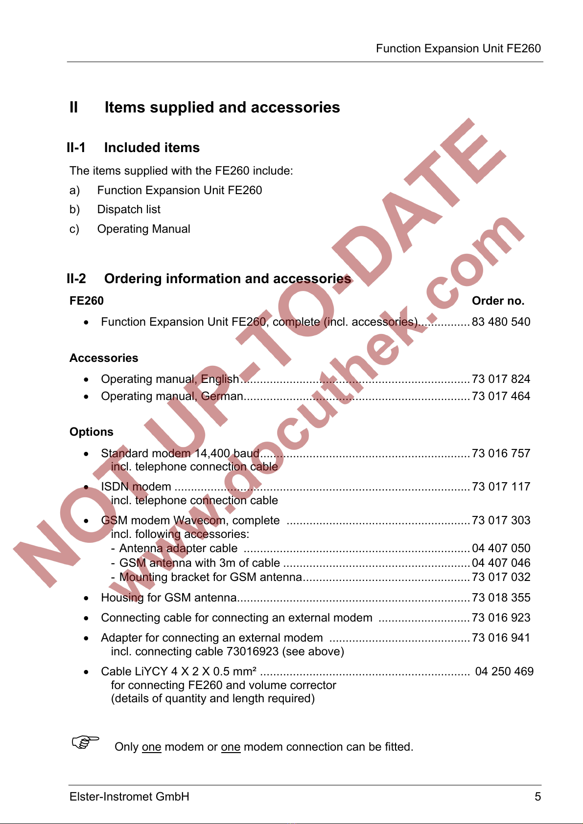
II-2 Ordering information and accessories
FE260 Order no.
• Function Expansion Unit FE260, complete (incl. accessories)................ 83 480 540
Accessories
• Operating manual, English...................................................................... 73 017 824
• Operating manual, German..................................................................... 73 017 464
Options
• Standard modem 14,400 baud................................................................ 73 016 757
incl. telephone connection cable
• ISDN modem .......................................................................................... 73 017 117
incl. telephone connection cable
• GSM modem Wavecom, complete ........................................................ 73 017 303
incl. following accessories:
- Antenna adapter cable ..................................................................... 04 407 050
- GSM antenna with 3m of cable ......................................................... 04 407 046
- Mounting bracket for GSM antenna................................................... 73 017 032
• Housing for GSM antenna....................................................................... 73 018 355
• Connecting cable for connecting an external modem ............................ 73 016 923
• Adapter for connecting an external modem ........................................... 73 016 941
incl. connecting cable 73016923 (see above)
• Cable LiYCY 4 X 2 X 0.5 mm² ................................................................ 04 250 469
for connecting FE260 and volume corrector
(details of quantity and length required)
Only one modem or one modem connection can be fitted.

Function Expansion Unit FE260
6 Elster-Instromet GmbH
1 Brief description
The Function Expansion Unit FE260 is used for expanding the functions of a volume
corrector in the LIS-200 range, such as for example the EK260 from software version 2.02.
In the current level of expansion it fulfils the following tasks:
• Intrinsically safe power supply for the volume corrector.
• Ex isolation for the digital outputs (pulse / signalling outputs).
• Ex isolation of the internal data interface.
• Remote data transmission on request, can also be retrofitted.
• Local data transmission on request (cannot be retrofitted)
For the "AC" versions the power supply is provided as 230 V or 115 V alternating voltage
(mains voltage) and for the "DC" version it is provided as 10 to 30 V direct voltage.
Electrical
isolation
Pulse
outputs
(4 x
RS232
Interface
Optical
Interface Local
interface
(optional)
Telecommu-
nications
network
230 V AC
(115 V AC)
Modem
(optional)
RS485
Interface
Pulse
ouputs
(4 x)
Intrinsically
safe circuits
Power
supply
8,5 V
Fig. 1: Block diagram of the FE260,"AC" versions.

Function Expansion Unit FE260
Elster-Instromet GmbH 7
Telecommu-
nications
network
Modem
(optional)
Local
interface
(optional)
Pulse
outputs
(4 x)
Optical
Interface
RS232
Interface
Electrical
isolation
10...30 V DC
Voltage
monitor
Intrinsically
safe circuits
Pulse
ouputs
(4 x)
RS485
Interface
Power
good
signal
Power
supply
8,5 V
Fig. 2: Block diagram of FE260, "DC" version.
Two signalling lamps fitted to the cover indicate the following states:
• “Power”: The device is ready for operation.
• “Online”: Data transmission is running via the installed or connected modem. Data
is being transmitted between the connected volume corrector and the
readout station or control station over a telecommunications network.
At the start of a remote data transmission "Online" flashes with the ringing
tones which the modem receives.
Function Expansion Unit FE260
8 Elster-Instromet GmbH
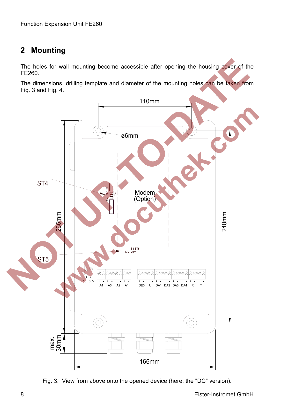
2 Mounting
The holes for wall mounting become accessible after opening the housing cover of the
FE260.
The dimensions, drilling template and diameter of the mounting holes can be taken from
Fig. 3 and Fig. 4.
110mm
166mm
DE3
Modem
(Option)
266mm
ST5
10...30V
+
max.
30mm
A4
-
+-+-
A3
-+-+
A2 A1
+
12V 24V
ST5
ST4
ST4
inv.non-inv.
ø6mm
240mm
+--+-++
U
-
DA1 DA2
-
R
-+-++
DA3 DA4
-
T
Fig. 3: View from above onto the opened device (here: the "DC" version).

Function Expansion Unit FE260
Elster-Instromet GmbH 9
167mm
a
c
b
7mm
100mm
Fig. 4: View from the front onto the cable entries
a = Plastic gland for mains supply 230VAC
b = Plastic gland for telephone or antenna cable
c = Earth connection
! As “associated electrical equipment”, the FE260 cannot be installed in Zone 1. (See
[DIN] EN 60079-10 and [DIN) EN 60079-14.)
For versions of the FE260 with a GSM modem, the supplied antenna must be mounted,
e.g. on the wall. A mounting bracket is provided in the supplied items for this.
A housing for installation of the antenna can be ordered separately (see Chapter II).
Function Expansion Unit FE260
10 Elster-Instromet GmbH
3 Installation
! The terminals of the FE260 are freely accessible on opening the housing. To avoid
damage to the device, it must be ensured that no electrostatic discharge (ESD)
from persons via the FE260 can occur.
To prevent this, the installer should discharge himself by touching an earthed
metallic object directly before connecting a cable.
! After installation replace all unused cable glands by the enclosed plugs to ensure
that the housing is sealed.
3.1 Power supply to the FE260
3.1.1 "AC" versions (for alternating voltage 230 V or 115 V)
! The "AC" versions of the Function Expansion Unit FE260 are supplied with
mains voltage at 230 V or 115 V. Avoid touching live parts, because this can
be highly dangerous.
Switch off the mains voltage before starting installation or wire connection
work and before opening the housing.
Only switch the mains voltage on again after all the work has been
completed and the housing has been firmly closed.
Mains alternating voltage should be connected to the terminal block labelled "230V" or
"115V" and the earth conductor should be connected to "PE".
! Depending on the version, the FE260 is suitable for power supply of 230 V
or 115 V alternating voltage. In order to avoid damaging the device, only
connect the voltage labelled on the terminals.
3.1.2 "DC" version (for direct voltage of 10 to 30 V)
The "DC" version of the FE260 is suitable for a direct-voltage power supply in the range
from 10 to 30 V. It can be operated, for example, with nominal voltages of 12 V or 24 V.
The "DC" version (not the "AC" versions) have the possibility of monitoring the supply
voltage on the terminal "10...30V". In this respect, the terminal "DE3" must be connected
to the terminal of the same name on the volume corrector. (→0
Terminal layout, page 13).
The monitoring can be set for nominal voltages of 12 V and 24 V. For further details: see
Chapter 4.1.
Function Expansion Unit FE260
Elster-Instromet GmbH 11
3.2 Screening and earthing
The cables for connection to the intrinsically safe electrical circuits (blue terminal block)
and to the outputs A1 to A4 have a screen which must be earthed at both ends to prevent
interference due to high frequency electromagnetic fields.. The screen must be connected
all round, complete and flat. The FE260, similar to the volume corrector (e.g. EK260) to be
connected, has special metallic EMC cable glands for this.
3.3 Intrinsically safe electrical circuits
The FE260 is approved according to DIN EN 50020 as “associated electrical equipment” in
the Category “ia” (see Chapter A-2). The blue terminal block on the right-hand side
includes three intrinsically safe circuits. If an intrinsically safe device is connected to them
(e.g. an EK260 volume corrector) which is located in the area subject to explosion hazards
(Zone 1), then the appropriate regulations must be followed. The implications of this
include:
! Follow the stipulations in the relevant regulations and standards, in particular DIN
EN 60079-14 (VDE 0165 Part 1) and DIN EN 50014.
! Make sure that the limits quoted in the certificate of conformance (Chapter A-2) do
not exceed the limits quoted in the certificate of conformance for the intrinsically
safe device to be connected.
! Only cable may be used for the intrinsically safe electrical circuits which fulfils the
following requirements according to DIN EN 60079-14, Section 12.2.2.1:
Insulated cables with a proof voltage of at least 500 VAC between conductor-earth,
conductor-screen and screen-earth.
If fine-stranded conductors are used, the conductor ends must be protected
against splaying out, e.g. by the use of wire-end sleeves.
The diameter of individual conductors as well as single wires in fine-stranded
conductors must not be less than 0.1 mm.
! Since the cable screens are connected at both ends, the volume corrector housing
must be electrically connected to the earthed housing of the FE260 via a potential
equalisation conductor. The potential equalisation conductor must have a cross-
sectional area of at least 4 mm². (DIN EN 60079-14, Sect. 12.2.2.3).
The FE260 is earthed using terminal "c" in Fig. 4 (page 9).
Furthermore all other relevant requirements in DIN EN 60079-14 must be fulfilled.
Screened cables must be used for reasons of electromagnetic compatibility (EMC). In this
respect, labelling of the cables or a special sheath colour is not necessary according to
DIN EN 60079-14, Sect. 12.2.2.6.
Function Expansion Unit FE260
12 Elster-Instromet GmbH
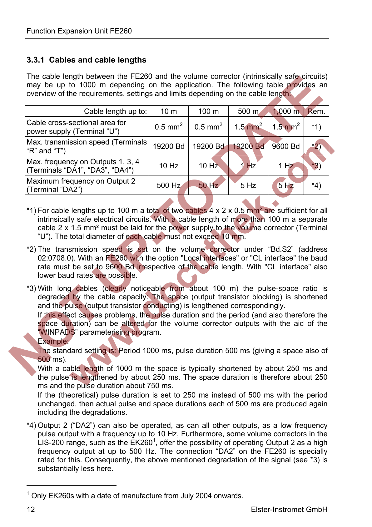
3.3.1 Cables and cable lengths
The cable length between the FE260 and the volume corrector (intrinsically safe circuits)
may be up to 1000 m depending on the application. The following table provides an
overview of the requirements, settings and limits depending on the cable length:
Cable length up to: 10 m 100 m 500 m 1,000 m Rem.
Cable cross-sectional area for
power supply (Terminal “U”) 0.5 mm20.5 mm21.5 mm21.5 mm2*1)
Max. transmission speed (Terminals
“R” and “T”) 19200 Bd 19200 Bd 19200 Bd 9600 Bd *2)
Max. frequency on Outputs 1, 3, 4
(Terminals “DA1”, “DA3”, “DA4”) 10 Hz 10 Hz 1 Hz 1 Hz *3)
Maximum frequency on Output 2
(Terminal “DA2”) 500 Hz 50 Hz 5 Hz 5 Hz *4)
*1) For cable lengths up to 100 m a total of two cables 4 x 2 x 0.5 mm² are sufficient for all
intrinsically safe electrical circuits. With a cable length of more than 100 m a separate
cable 2 x 1.5 mm² must be laid for the power supply to the volume corrector (Terminal
“U”). The total diameter of each cable must not exceed 10 mm.
*2) The transmission speed is set on the volume corrector under “Bd.S2” (address
02:0708.0). With an FE260 with the option "Local interfaces" or "CL interface" the baud
rate must be set to 9600 Bd irrespective of the cable length. With "CL interface" also
lower baud rates are possible.
*3) With long cables (clearly noticeable from about 100 m) the pulse-space ratio is
degraded by the cable capacity: The space (output transistor blocking) is shortened
and the pulse (output transistor conducting) is lengthened correspondingly.
If this effect causes problems, the pulse duration and the period (and also therefore the
space duration) can be altered for the volume corrector outputs with the aid of the
“WINPADS” parameterising program.
Example:
The standard setting is: Period 1000 ms, pulse duration 500 ms (giving a space also of
500 ms).
With a cable length of 1000 m the space is typically shortened by about 250 ms and
the pulse is lengthened by about 250 ms. The space duration is therefore about 250
ms and the pulse duration about 750 ms.
If the (theoretical) pulse duration is set to 250 ms instead of 500 ms with the period
unchanged, then actual pulse and space durations each of 500 ms are produced again
including the degradations.
*4) Output 2 (“DA2”) can also be operated, as can all other outputs, as a low frequency
pulse output with a frequency up to 10 Hz, Furthermore, some volume correctors in the
LIS-200 range, such as the EK2601, offer the possibility of operating Output 2 as a high
frequency output at up to 500 Hz. The connection “DA2” on the FE260 is specially
rated for this. Consequently, the above mentioned degradation of the signal (see *3) is
substantially less here.
1Only EK260s with a date of manufacture from July 2004 onwards.

Function Expansion Unit FE260
Elster-Instromet GmbH 13
3.3.2 Terminal layout
With an EK260 volume corrector, set “TypS2” = “2” before you connect it to the
FE260 in order to avoid damage to the devices.
Cable 1
White
+ +
Brown
FE260
U - - Uext
Volume corrector
e.g. EK260
Green
+ +
Yellow
R - - R
Grey
+ +
Pink
T - - T
Blue
+ +
Red
„DC“ version
only
DE3 - - DE3
White
+ +
Brown
DA1 - - DA1
Green
+ +
Yellow
DA2 - - DA2
Grey
+ +
Pink
DA3 - - DA3
Blue
+ +
Red
DA4 - - DA4
if present
Cable 2
On the EK260 the terminals “R+”, “R-“, “T+” and “T-“ are also labelled with “CS”, “RD”,
“RS” and “TD”. When connecting the FE260, these designations have no significance. The
terminals “Ri” and “Gnd” on the EK260 remain unconnected.
The cable designations (Cable 1 and Cable 2) and the suggested core colours are based
on the use of two similar cables, LiYCY 4 x 2 x 0.5 mm², twin-twisted with colour code
according to DIN 47100. Suitable cables can also be obtained from Elster-Instromet (see
II-2, Options).
With "AC" versions (with 230V or 115V power supply) the blue and red wires of Cable 1
remained unused. They should then be cut off at both ends flush with the cable sheath or
safely insulated to prevent hazardous short circuits from forming.
Of course, other cables can also be used provided they conform to the requirements
quoted in 0. Similarly, a different designation of the core colours is possible.
Function Expansion Unit FE260
14 Elster-Instromet GmbH
3.4 Digital Outputs A1 to A4
The terminals “A1” to “A4” are individually electrically isolated digital outputs which pass
on the incoming signals on “DA1” to “DA4” (pulse or message signals) from the volume
corrector unmodified with respect to time. Due to the approved electrical isolation, any
devices without Ex approval can be connected to A1 to A4, provided they do not exceed
the limits quoted in the chapter “Technical Data”.
3.5 Modem
On request, the FE260 can be fitted with an integral modem or a connection for a separate
modem in order to read out the data from the connected volume corrector by remote data
transmission. Various modems are possible.
For data transfer via the FE260 the EK260 requires at least the software version 2.02.
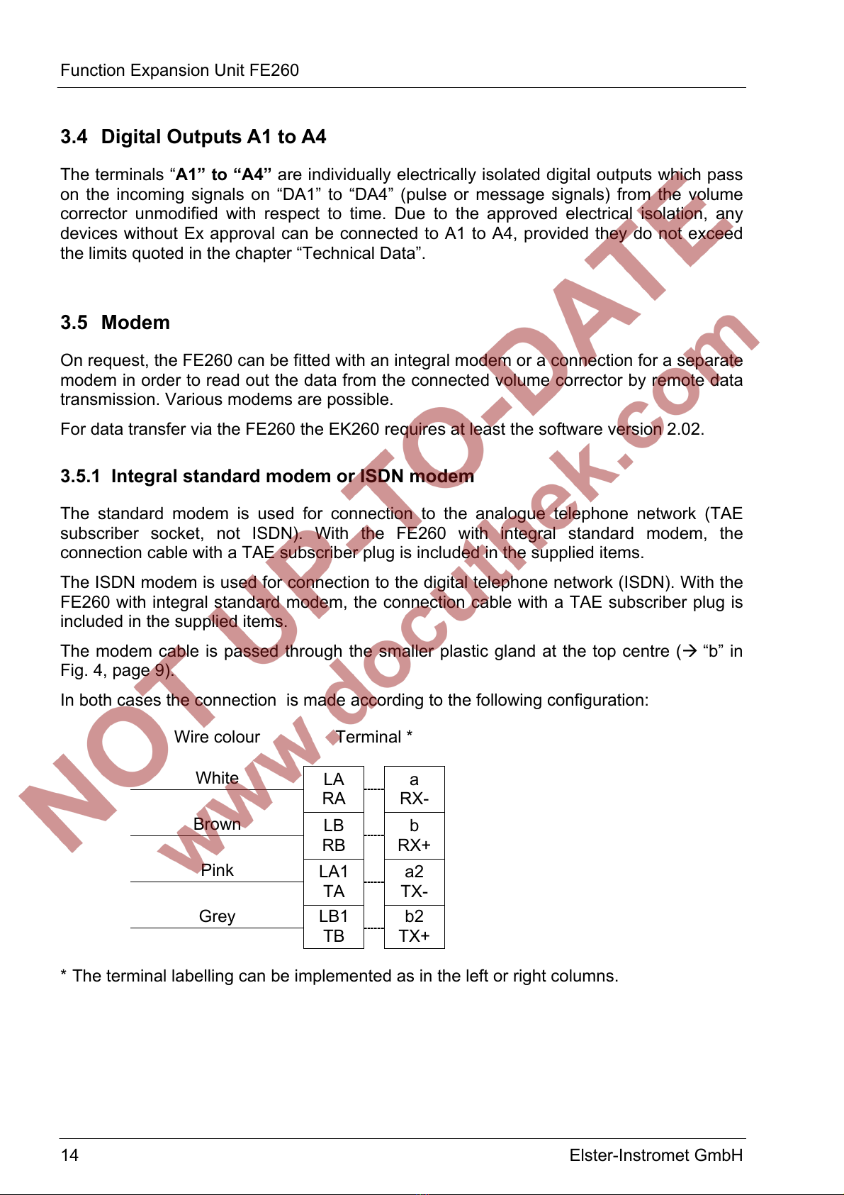
3.5.1 Integral standard modem or ISDN modem
The standard modem is used for connection to the analogue telephone network (TAE
subscriber socket, not ISDN). With the FE260 with integral standard modem, the
connection cable with a TAE subscriber plug is included in the supplied items.
The ISDN modem is used for connection to the digital telephone network (ISDN). With the
FE260 with integral standard modem, the connection cable with a TAE subscriber plug is
included in the supplied items.
The modem cable is passed through the smaller plastic gland at the top centre (“b” in
Fig. 4, page 9).
In both cases the connection is made according to the following configuration:
Wire colour
Terminal *
White
LA
RA
a
RX-
Brown
LB
RB
b
RX+
Pink
LA1
TA
a2
TX-
Grey
LB1
TB
b2
TX+
* The terminal labelling can be implemented as in the left or right columns.

Function Expansion Unit FE260
Elster-Instromet GmbH 15
3.5.2 Integral GSM modem
The GSM modem is used for data transmission via the GSM network (radio network,
“mobile phone network”). With the FE260 with an integral GSM modem the antenna
required for this is included in the supplied items.
Similarly, a mounting bracket for mounting the antenna (e.g. on the wall) is also included in
the supplied items. A housing for installation of the antenna can be ordered separately
(see Chapter II).
Once the antenna has been mounted, the antenna cable is passed through the top centre
plastic gland (“b” Fig. 4, page 9). Where applicable, the sealing ring must for this first be
removed from the gland and pulled over the antenna cable connection.
Only use the top centre plastic gland for the antenna cable so that the point of
connection does not form a short circuit to the earthed housing.
Then the antenna cable is connected to the modem within the FE260 using the short
cable.
Following this, the connected cables should be pulled back into the gland until about half
of the point of connection is located in the gland. The cable can then be fixed by screwing
the gland closed.
To operate the modem you need a SIM card from your provider (e.g. D1 or D2 network)
with the following properties:
- Released for data transmission via GSM modem.
- PIN interrogation switched off.
A "normal" SIM card for mobile telephones cannot be used.
Disconnect the FE260 from the power supply before you insert the SIM card
into the modem drawer.
Then close the drawer carefully and switch on the power supply again.

Function Expansion Unit FE260
16 Elster-Instromet GmbH
3.5.3 Connection of a separate modem
For the connection of a CL modem: refer to Chapter 3.5.4, page 17.
If the FE260 is implemented with a connection for a separate modem, you can connect a
commercially available modem to it to read out the volume corrector by remote data
transmission. You can use a modem with or without automatic call acceptance.
A modem without automatic call acceptance must be parameterised such that it sends the
text “Ring” over the data line to the volume corrector for each ringing tone (for each “ring”).
This then causes the modem to accept the call (“lift receiver”) after the set number of
ringing tones (“Num.T”, 0 in Chapter 4.3).
Depending on the connected modem, “Md.S2” should be set in the volume corrector:
• Modem without automatic call acceptance ... Md.S2 = “3”
• Modem with automatic call acceptance1....... Md.S2 = “5”
The modem connection in the FE260 can be configured as an RS-232 or RS-485
interface. To enable this, there is a jumper labelled “RS-232” and “RS-485” on the board
with the terminals for the modem connection.
Before connecting a commercially available modem to the RS-232 interface,
make sure that the jumper in the vicinity of the modem connection terminals is
plugged on the side labelled “RS-232”.
Connection diagram:
Brown
Green
White
Yellow
Pink
Grey
DTR / RTS
RI
GND
DSR / DCD / CTS
RxD
TxD
FE260
5
9
4
GND
RI
DTR
2
3
1
RxD
TxD
DCD
Modem
The modem signals “DCD”, “DTR” and “RI” are not used by the FE260. These terminals
may be connected or left unconnected. Connection of “RxD”, “TxD” and “GND” is needed.
1E.g. when using the option "Local interfaces", see Chap. 0, page 22.
Function Expansion Unit FE260
Elster-Instromet GmbH 17
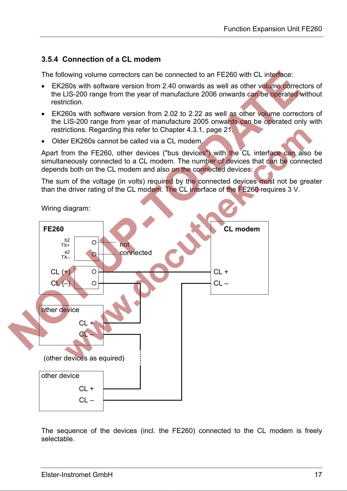
3.5.4 Connection of a CL modem
The following volume correctors can be connected to an FE260 with CL interface:
• EK260s with software version from 2.40 onwards as well as other volume correctors of
the LIS-200 range from the year of manufacture 2006 onwards can be operated without
restriction.
• EK260s with software version from 2.02 to 2.22 as well as other volume correctors of
the LIS-200 range from year of manufacture 2005 onwards can be operated only with
restrictions. Regarding this refer to Chapter 4.3.1, page 21.
• Older EK260s cannot be called via a CL modem.
Apart from the FE260, other devices ("bus devices") with the CL interface can also be
simultaneously connected to a CL modem. The number of devices that can be connected
depends both on the CL modem and also on the connected devices:
The sum of the voltage (in volts) required by the connected devices must not be greater
than the driver rating of the CL modem. The CL interface of the FE260 requires 3 V.
Wiring diagram:
FE260 CL modem
b2
TX+ *
a2
TX– *
not
connected
CL (+) *CL +
CL (–) *CL –
other device
CL +
CL –
(other devices as equired)
other device
CL +
CL –
The sequence of the devices (incl. the FE260) connected to the CL modem is freely
selectable.

Function Expansion Unit FE260
18 Elster-Instromet GmbH
4 Initial operation
For initial operation the following steps should be carried out:
4.1 Power supply
• Once all cables are connected and the housing firmly closed, switch on the FE260
power supply (mains voltage for the "AC" versions).
• Check the “Power” signal lamp on the cover of the FE260. A continuous green signal
indicates that the FE260 power supply is functioning correctly.
• Check the power supply of the connected volume corrector by bringing the status
messages into the volume corrector display. If the message “Batt. operat” (message
"15" in status "St.SY") is not entered here, the volume corrector is being supplied from
the FE260.
If the volume corrector displays the message "Batt. operat" (message "15" in "St.SY",
the volume corrector is not being supplied from the FE260. In this case check that the
intrinsically safe electrical circuits are connected correctly.
Only the "DC" version (not the "AC" versions) have the possibility of monitoring the supply
voltage on the terminal "10...30V". When a voltage limit is undercut, the connected volume
corrector receives a corresponding signal through the "DE3" terminal, setting the status
message "8" in the status "St.3" of the volume corrector. Due to this status signal, the
volume corrector can for example, with appropriate parameterisation, then activate an
output or execute another event-controlled action.
If you would like to use the voltage monitoring of the "DC" version, carry out the following
steps:
• Set the voltage limit with jumper "ST5" (→Fig. 3, page 8) appropriate to your power
supply:
- to the position "12" for power supply with a nominal voltage of 12 V
(The limit for the warning is then approx. 11 V.)
- to the position "24" for power supply with a nominal voltage of 24 V
(The limit for the warning is then approx. 20 V.)
• Make sure also that the terminal "DE3" is connected to the terminal of the same name
on the volume corrector. (→3.3.2 Terminal diagram, page 13).
• On the volume corrector set the value "MdME3" (in the display column "Inp.") to "3".
• If the monitoring does not function, also check the following values in the display
column "Inp." on the volume corrector:
- SC.I3 = 0003:228_0 ("St.E3")
- L1.I3 = 1
- SpI3 = 0.08_03:1.1 ("I3 Warn.sig↑“)

Function Expansion Unit FE260
Elster-Instromet GmbH 19
4.2 Digital outputs
If you are using digital outputs, check whether the devices connected to terminals A1 to A4
are receiving the volume corrector signals.
If this is not the case, then check:
• the output settings of the volume corrector according to its operating manual and the
details in Chapter 0.
• by how far the technical data for the outputs (Chapter B) match the connected device.
• whether all specifications regarding cables and cable lengths in Chapter 0 have bee
fulfilled.
• whether the signal inversion of the outputs may possibly be incorrectly set (see
above).
• The transfer of an HF signal via output "DA2" functions with an EK260 with a date of
manufacture from July 2004 onwards.
Signal inversion
With the aid of the jumper "ST4" (→Fig. 3, page 8) you can set whether the output signals
are inverted with respect to those supplied by the volume corrector.
• Position "non-inv." The signals are not inverted (standard setting).
• Position "inv." The signals are inverted.
"Inverted" signifies that the FE260 output is switched through (conducts) when the volume
corrector output blocks and vice versa.

Function Expansion Unit FE260
20 Elster-Instromet GmbH
4.3 Modem
When using an integral or connected modem, the interface of the volume corrector must
be parameterised as follows (all values can be found in the menu “Ser.IO” on the volume
corrector):
AD Address Designation Setting Meaning Rem.
Md.S2 2:0705 Mode 3 or 5 *1)
DF.S2 2:0707 Data format 0 7 data bits, even parity,
1 stop bit ("7e1")
Bd.S2 2:0708 Initial baud rate 19200 or 9600 baud *2)
TypS2 2:070A Type of interface 2 RS-485 *3)
Num.T 2:0720 Ringing tones before call
acceptance
*4)
CW1.S 5:0150 Call Time Window 1 Start *5)
CW1.E 5:0158 Call Time Window 1 End
CW2.S 6:0150 Call Time Window 2 Start
CW2.E 6:0158 Call Time Window 2 End
1:01FB Activation with external
power supply
1 Remains continuously
active
*6)
2:0709 "Identification baud rate" 19200 or 9600 baud *2), *6)
*1) When using a modem without automatic call acceptance (standard case), Md.S2 = “3”
must be set and MD.S2 = “5” for modems with automatic call acceptance (e.g. with an
FE260 with the option "Local interfaces" or "CL interface").
*2) 19200 Bd is standard. With longer lengths of cable between the FE260 and the volume
corrector (refer to Chapter 0, page 12) and when using the option "Local interfaces" or
"CL interface", the baud rate may be set to a maximum of 9600 Bd.
When using an FE260, the starting baud rate "Bd.S2" and the "Identification baud rate"
(address 2:0709) must always be set to the same value.
*3) The setting of the type of interface is only needed with those types of volume corrector
where “TypS2” is present in the display (e.g. EK260).
*4) The adjustable number of ringing tones (rings) before call acceptance depends on the
modem used. With a GSM modem it should be set to "1" and with other modems to a
value between "2" and "9".
With a modem with automatic call acceptance, “Num.T” has no significance.
*5) Volume correctors in the LIS-200 range, such as the EK260, offer at least two time
windows within which calls can be accepted for data interrogation. Outside of these
time windows calls are ignored, so that, for example, a person located in the station
can be called via a telephone connected to the same telephone line.
*6) The values with the addresses 1:01FB and 2:0709 are not always available in the
volume corrector display. They can be changed, for example, via the optical interface
using the parameterisation software "WinPADS". The standard setting is “1:01FB = 1”
and "2:0709 = 19200".
This manual suits for next models
1
Table of contents
Popular Power Supply manuals by other brands


Hioki
Hioki 3272 instruction manual

Horizont
Horizont ranger AN3000 instruction manual

Rutland
Rutland ESB377 GSM installation guide

Insignia
Insignia NS-GPSV1303 Quick setup guide

TDK-Lambda
TDK-Lambda Genesys GSPS10-3000 Product Safety & Installation Manual

Larson Electronics
Larson Electronics DCP-38-42V instruction manual


