*2
@
External output/specificat~ons
I-.:
4.
Handlingand InstallationMethod
@
External output usage method
RUN
...........
Whether the GOT is operating correctly or not is output ex-
ternally.
(Outputstatus)
ON: When operating normally
OFF: When operatingabnormally
Usewhen you want to monitorGOT operationusingthe PC
CPU. For the usage methoduse the Input modulereceived
PC programto check this output.
OUTPUT
..
..
This is not used.
BCAUTION
Usethis moduleinthegeneralspecificationenvironmentprescribed
inthe GOT User'sManual.
If th~smodule is used outsideof the general specificationenviron-
ment, electric shock, fire, malfunctionor damageanddegradation
tothe productcould result.
When installingor removingthe Power SupplyModuleinor from the
GOT be sure to removethe power cablefrom the Power Supply
Module'sterminal block.Troublecould result ~fwork is conducted
while the power cable is connected.
Correctlyinstallthewiringtothe Power Supply Moduleafter check-
ing
the
ratedvoltage and terminallayoutfor theproduct.Usingother
than the rated power or incorrectwiring could cause fire or other
trouble.
Followthe guide
when
installingthe screwsinthe GOT installation
areaand conductthe installationusingthe modulefixing screws. If
themoduleisnotcorrectlyinstalledthen maMvlction
or
trouble
could
result or the modulecouldfall off.
Takeprecautionsso that debris, such as sawdust
or
wiring debris,
does not get insidethe module. If such debris does get inside it
could causefire, trouble, or malfunction.
.Do not disassembleor modify the module. Doing so could cause
trouble, malfunction,injury, or fire.
Do not touch the module'spnntedwiring boardor electroniccom-
ponents.Doing
so
couldcausetrouble inthe module.
.The module is made of plasticso do not drop it or subject it to
strongimpacts.Doing
so
couldcausetrouble.
Do not removethe module printedwiring boardsfrom the case.
Doing
so
couldcausetrouble.
When discardingthe producttreat it as industrialwaste.
@
Installthe power supply unit inthe GOT,
and tighten the screw to secure it.
To removethepower
supply
unit,
loosen
thescrew, andthen reversethe installa-
tion procedure.
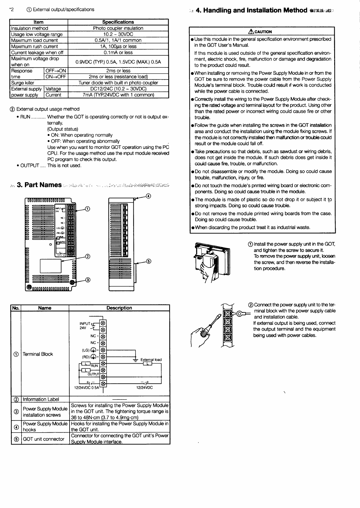
Description
12
Screwsfor installingthe Power Supply Module
inthe GOT unit.The tighteningtorque range is
36
to 48N.c-n (3.7to 4.9mg.cm)
Hooksfor installingthePowerSupply Modulein
the GOT unit.
Connectorfor connectingtheGOT unit'sPower
SuDolvModuleinterface.
No.
@
@
@
@
@
@Connectthe power supplyunittotheter-
minalblockwith the powersupply cable
@=
and installationcable.
If externaloutput is beingused,connect
the output terminaland the equipment
beingusedwith power cables.
Name
Terminal Block
InformationLabel
Power
Module
installation
screws
PowerSupplyModule
hooks
unit
connector


