eltima electronic 50051 User manual
1
© Copyright eltima electronic 2017
Assembly instructions
eltima carrier systems
version: 11.2017
© Copyright eltima electronic 2017

2 Part list
© Copyright eltima electronic 2017
Part list
Profile rail 20 x 20 mm
Angle clamp bracket
Profile rail 20 x 40 mm
Angle bracket
Cover cap for
angle bracket
Cap screws M5 x 8,
for angle bracket
t-slot nut
Lenshead screw M5 x 10
Allen key
3 mm
Large corner plate
Small corner plate
¼“ screw

3 Content
© Copyright eltima electronic 2017
Content
Part list..................................................................................................... 2
Content .................................................................................................... 3
Introduction.............................................................................................. 4
Intended use.................................................................................................. 4
Symbols ......................................................................................................... 4
Assembly technology ................................................................................ 5
Inserting the T-slot nut.................................................................................. 5
Corner connections ....................................................................................... 6
Cross connections.......................................................................................... 8
Carrier system for experimental photography............................................ 9
Carrier system for bird photography........................................................ 15
Carrier for insect photography................................................................. 16
Notices ................................................................................................... 18

4 Introduction
© Copyright eltima electronic 2017
Introduction
Dear customer,
thank you for purchasing the eltima carrier system. It should be a flexible and
reliable tool for you.
If you have any wishes and suggestions for improvement, do not hesitate and
let us know. Thus this product can grow and meet your requirements.
Please read these assembly instructions carefully before using the carrier sys-
tem. It will help you to familiarize with the structure and operation of this
system. This way you can fully exploit the benefits it offers you.
Intended use
The eltima carrier system has been developed for the mounting and fixing of
light barriers, light barrier accessories and other photographic accessories.
Use it only for this purpose.
Symbols
Tips for handling the device.
Important note on the function of the device.
Important note to avoid damage to the device or connected devices.
5 Assembly technology
© Copyright eltima electronic 2017
Assembly technology
This section describes the basic handling and assembly methods of the car-
rier system.
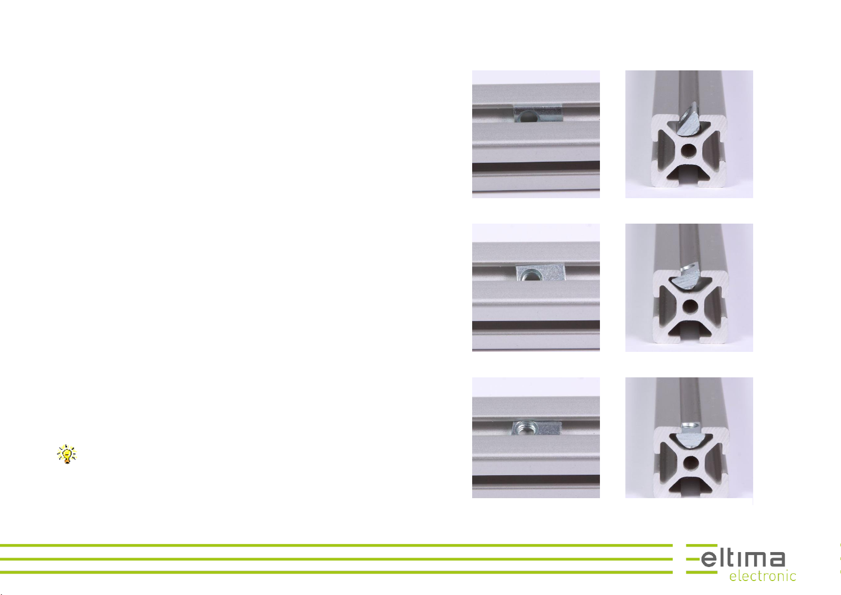
Inserting the T-slot nut
Profile rails, angle brackets and corner plates are bolt together by the means
of screws and T-slot nuts.
Place the T-slot nut with one edge ahead into the slot of a rail, like depicted
in Figure 1.
Then press the nut completely into the slot, like shown in Figure 2.
Push the second edge of the nut into the slot. The T-slot nut is now in posi-
tion, held by the spring-mounted ball of the nut, see Figure 3.
You can now move the T-slot nut to the right position by using a tool,
e.g. the included Allen key.
Figure 1: Placing the T-slot nut into the rail
Figure 2: inserting the second edge of the nut into the slot
Figure 3: T-slot nut in position
6 Assembly technology
© Copyright eltima electronic 2017
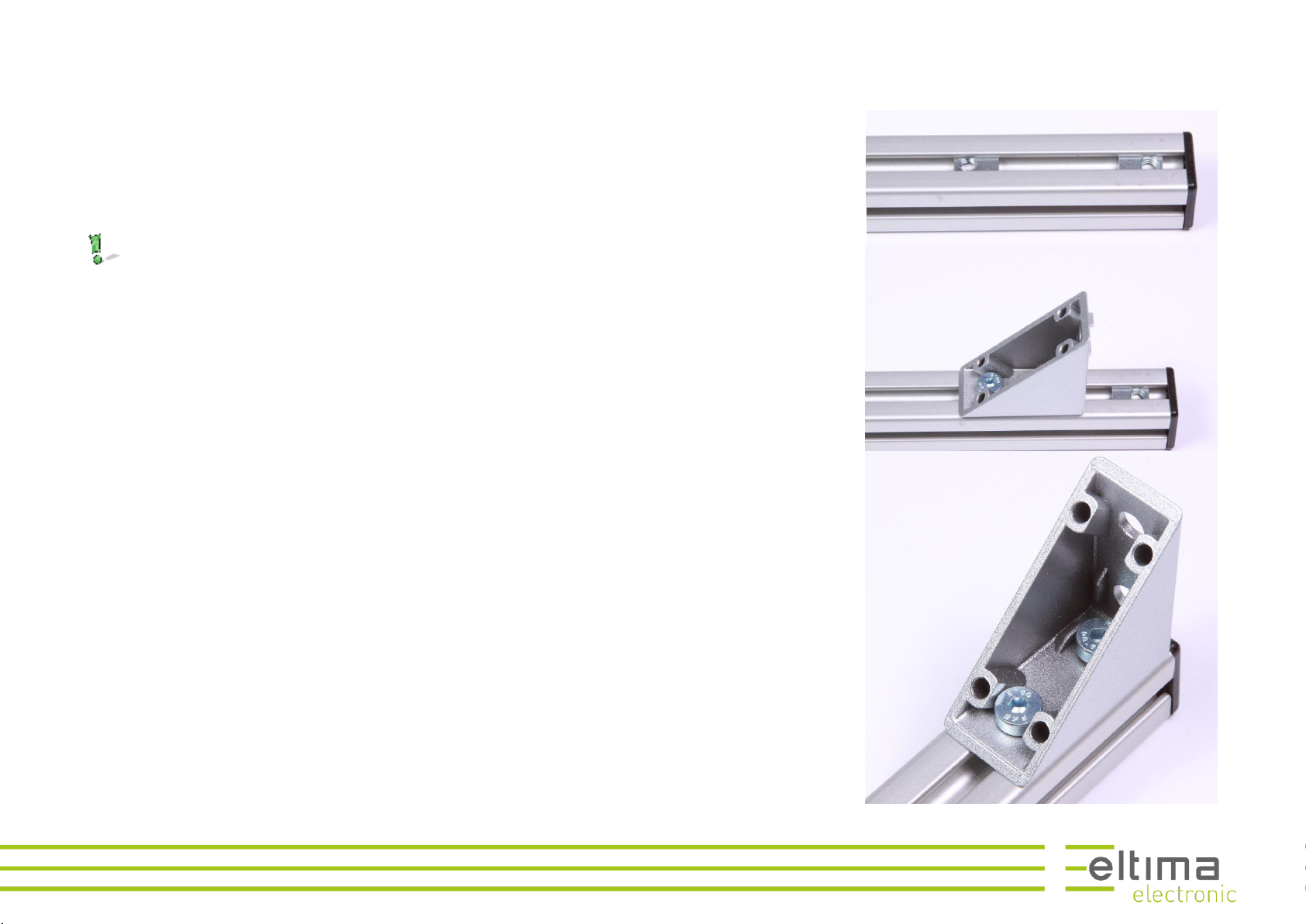
Corner connections
Two profile rails are connected by the means of angle brackets.
At first, insert two T-lot nuts at the end of the slot, see Figure 6.
The two threads of the nuts should point to the ends of the rail. This
is important, so that the angle can subsequently be pushed all the way
to the end of the rail.
Screw the bracket firstly with the outer screw, by turning it 1 to 2 turns, so
the bracket will still be loose, see Figure 5.
Then slide the bracket with the remaining hole over the second slot nut and
also loosely tighten the second screw, see Figure 4.
Now push the angle to the end of the rail.
Figure 6:
inserting the T-slot nuts
Figure 5:
insertig the first screw
Figure 4:
inserting the second screw

7 Assembly technology
© Copyright eltima electronic 2017
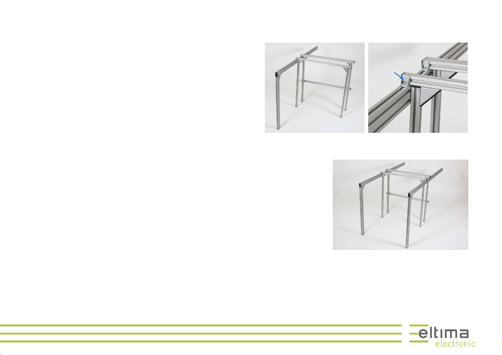
Insert as shown in Figure 6 two T-slot nuts in the slot of the second rail. Screw
the bracket as shown in Figure 4 on the second rail, but do not tighten the
screws. The two rails are now loosely connected, see Figure 7.
Slide the rails to the desired position and tighten the screws, see Figure 8.
Insert the cover cap by pushing it firmly into the bracket, see Figure 9.
Figure 7:
joining two rails
Figure 8:
aligning the rails
Figure 9:
tightened corner connec-
tion

8 Assembly technology
© Copyright eltima electronic 2017
Cross connections
Insert a T-slot nut at the desired position into the slot of a rail. Screw it loose
into the nut using a M5x10 lens head screw, see Figure 11.
At first just turn the screw by one turn. The bracket will hang loosely
and you can hook the rail easily into the bracket.
Hook the cross profile into the bracket at the right position and tighten the
screw, see Figure 10.
Figure 11: mounting the clamp bracket
Figure 10: completed cross connection
9 Carrier system for experimental photography
© Copyright eltima electronic 2017
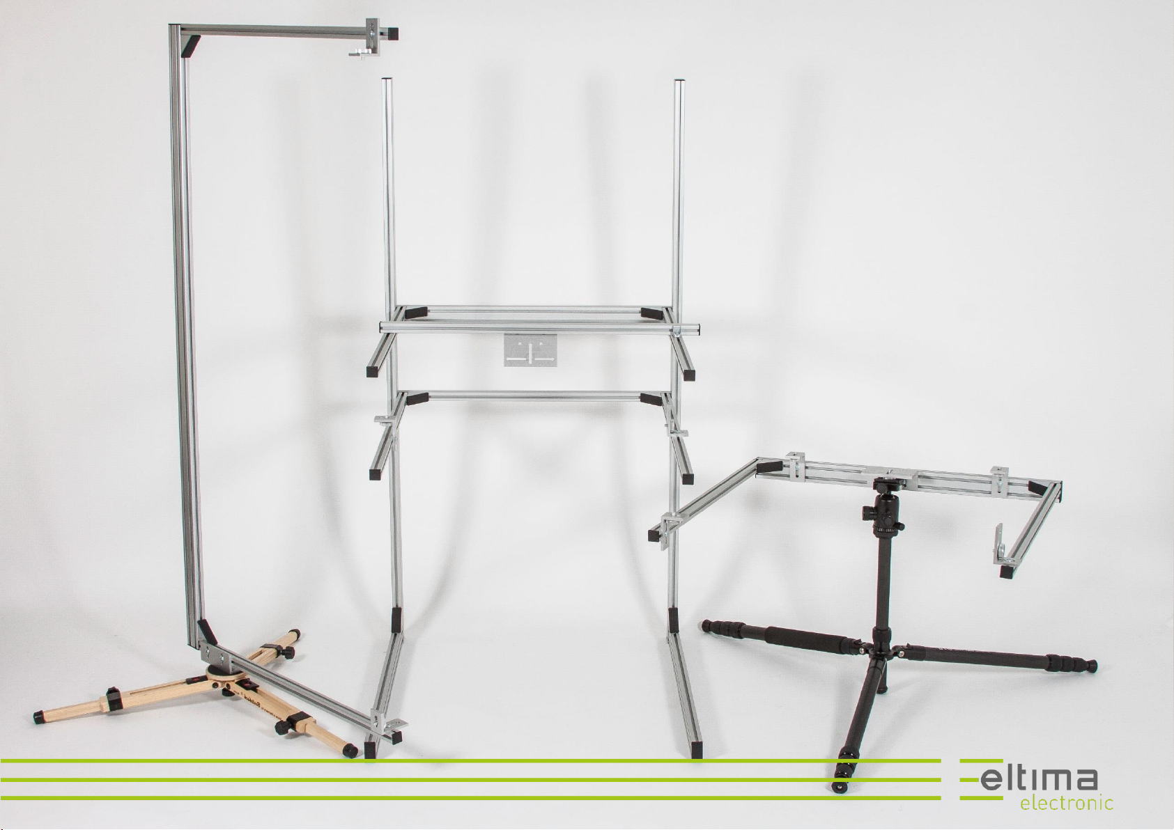
Carrier system for experimental photography
Bolt up two assemblies consisting of one rail 20x40x600 mm and one
20x40x1200 mm, like shown in Figure 13.
The assemblies will form the support frames of the carrier system.
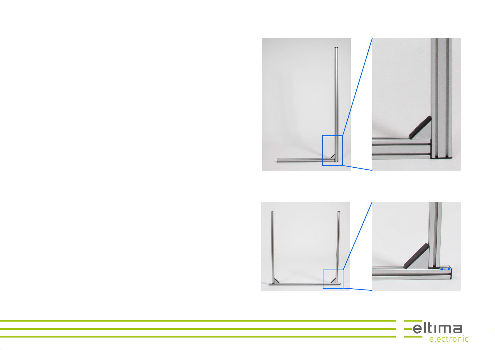
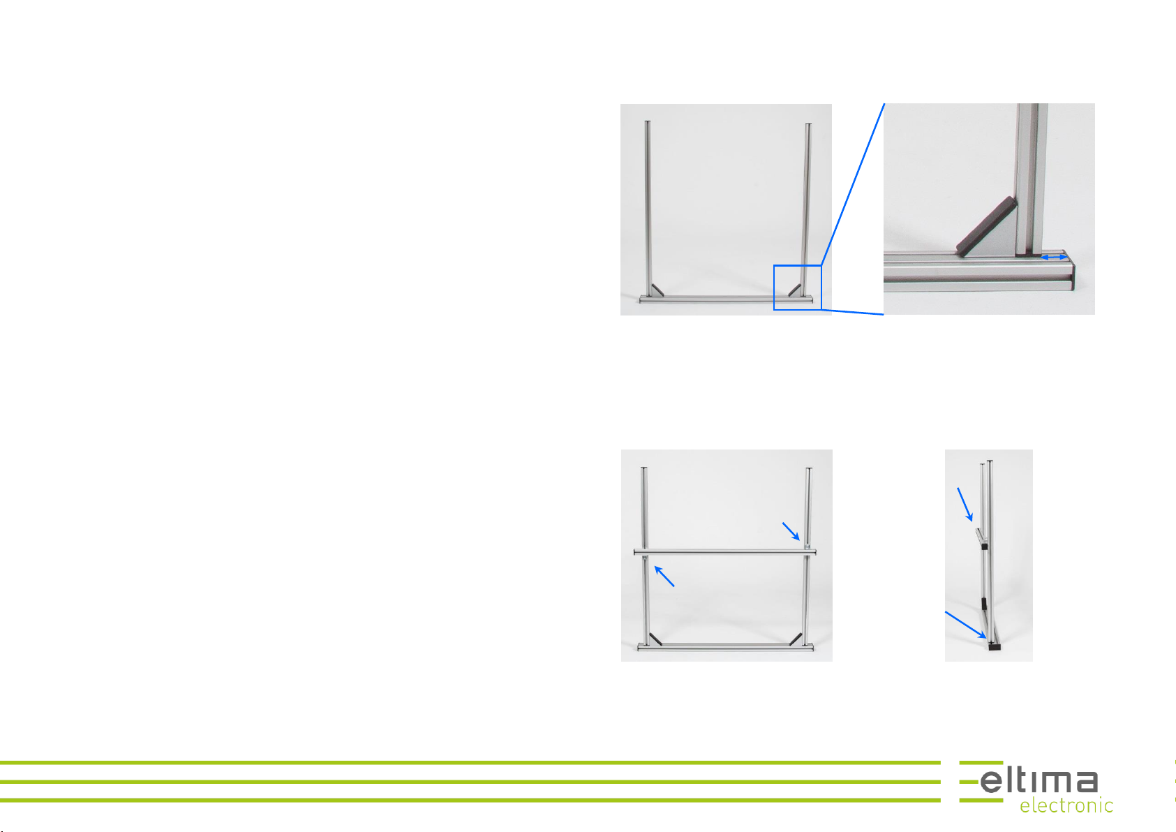
Bolt up three 20x20x600 mm rails to a frame like shown in Figure 12. The
spacing between the vertical rail and the end of the horizontal rail should be
app. 20 mm, i.e. breadth of a rail.
This will be the carrier for the light barrier, as far as needed.
2x
Figure 13: Aufbau der seitlichen Stützen
Figure 12: Aufbau des Trägers für die Lichtschranke
ca. 20 mm
10 Carrier system for experimental photography
© Copyright eltima electronic 2017
Bolt up two 20x20x600 mm rails and one 20x40x600 mm rail to a frame like
shown in Figure 15. The spacing between the vertical rail and the end of the
horizontal rail should be app. 20 mm, i.e. breadth of a rail.
This frame will form the carrier for the drop dispenser.
Bold a 20x20x600 mm rail on the flushly mounted side of the drop dispenser
frame, like shown on the right side of the Figure 14.
The clamp brackets must be mounted on opposite sides of the cross profile,
see the left side of Figure 14.
ca. 20 mm
Figure 15: Aufbau des Trägers für die Tropfenspender
Figure 14: Befestigung des Querprofils
Flushly mounted
side

11 Carrier system for experimental photography
© Copyright eltima electronic 2017
Screw three angle clamp brackets loosely to the positions indicated in Figure
16, to both support frames.
The two upper brackets will fix the frame for the drop dispenser, the lower
the one for the light barriers.
Hook the frame for the drop dispenser into the brackets of one support
frame, like shown in Figure 17. One bracket must be hooked in the upper nut
of the rail the other in the lower one, see Figure 18 left side.
Please take care that there is no gap between the rails, like shown in Figure
18 right side. This increases the stability of the system.
Figure 17:
hooking the frame for the
drop dispenser into the
support frame
Figure 18:
position of the angle clamp brackets
Figure 16:
details for hooking in the
drop dispenser frame
Leave no gap
between the
rails
Upper side
Lower side
12 Carrier system for experimental photography
© Copyright eltima electronic 2017
Now hook in the frame for the light barriers and tighten the screw, see Figure
19 left. The clamp bracket must be hooked in from the lower side of the rail,
see Figure 19 right.
Please take again care that there is no gap between the rails.
Next hook in the clamp brackets of the second support frame and tighten the
screws.
Pay attention that the two support frames must be positioned at the same
level. To check this out, use a meter rule.
Figure 20: hooking in the frame for the light barriers
The clamp bracket
must be hooked in
from the lower
side of the rail
Figure 19: hooking in the second support frame

13 Carrier system for experimental photography
© Copyright eltima electronic 2017
Mount the large corner plate on the lower side of the cross profile using 2 T-
slot nuts and 2 lenshead screws, see Figure 21.
Mount the 2 small corner plates on the rails of the light barrier frame, like
shown in Figure 22, by using T-slot nuts and lenshead screws.
The carrier system is now ready to use.
Figure 22: mounting of the large corner plate
Figure 21:
mounting of the small corner
plates
Light barrier
reflector

15 Carrier system for bird photography
© Copyright eltima electronic 2017
Carrier system for bird photography
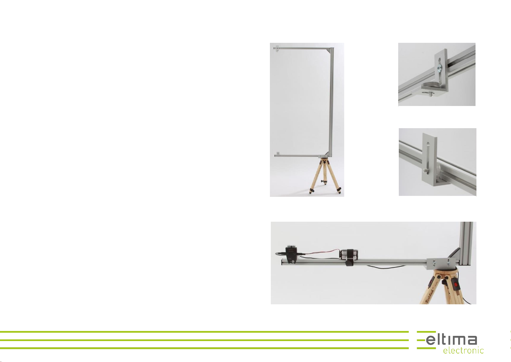
Assembly two 20x20x600 rails and one 20x40x1200 rail to a frame like shown
in Figure 24.
Mont on the upper rail a small corner plate for the reflector, like seen in Fig-
ure 25.
Mont on the lower rail a small corner plate for the light barrier, like seen in
Figure 26.
Mont on the lower rail a large corner plate for mounting the carrier on a tri-
pod, like seen in Figure 26.
The carrier system is now ready to use.
Figure 27: carrier system mounted on an tripod with installed light
barrier
Figure 26: corner plate for the
light barrier
Figure 25:
corner plate for the reflector
Figure 24: ready to use carrier
system
16 Carrier for insect photography
© Copyright eltima electronic 2017
Carrier for insect photography
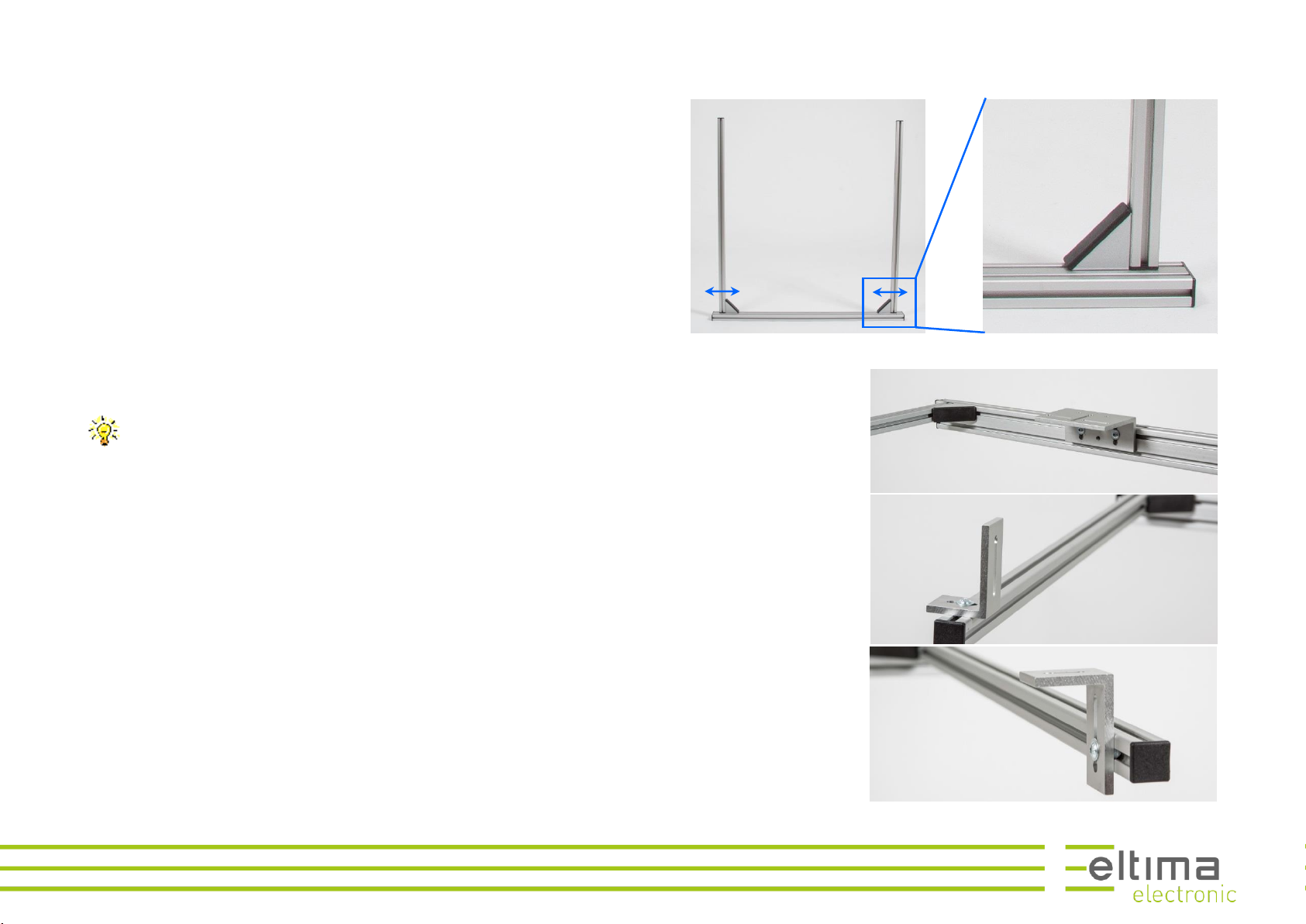
Assembly 2 20x20x600 rails and 1 20x40x600 rail to a frame like shown in
Figure 28.
Set the distance between the two vertical rails according to your needs.
Mount the large corner plate in the middle of the 20x40x600 rail, like shown
in Figure 29. It will be the support for the camera.
Put the large corner plate on the back side of the rail if you need more
distance between the camera and the light barrier.
Mount the two small corner plates for the reflector and the light barrier at
the ends of the frame like shown in the Figure 30 and Figure 31.
Figure 31: Frame for insect photography
Figure 30:
mounting of the large cor-
ner plate
Figure 29: corner plate for
the reflector
Figure 28: corner plate for
the light barrier

17 Carrier for insect photography
© Copyright eltima electronic 2017
Optionally, you can mount 2 small corner plates for fixing flashes, Figure 32.
The carrier system is now ready to use.
The carrier system can be used by holding it in the hands. It can be
carried to places were insects go to, like flowers or resting places, see
Figure 33.
The carrier system can be used monted on a tripod and installed in
front of bee or wasp nests, like in Figure 34.
Figure 33:
handheld usage
Figure 32:
usage on a tripod
Figure 34:
ready to use carrier

18 Notices
© Copyright eltima electronic 2017
Notices
19
© Copyright eltima electronic 2017
eltima electronic
Hans Gierlich
Staufenstraße 10
73230 Kirchheim unter Teck
07021-863444
www.eltima.de
This manual suits for next models
2
Table of contents


