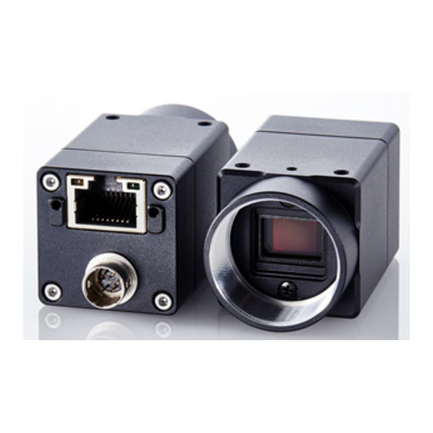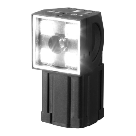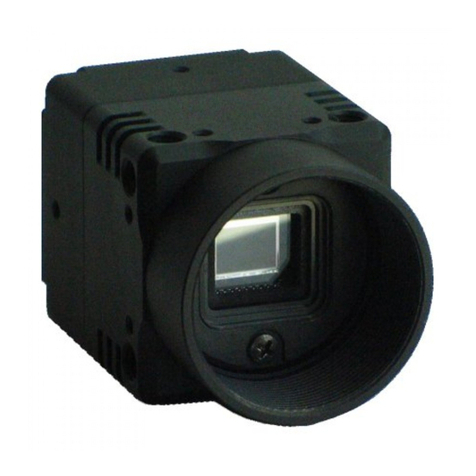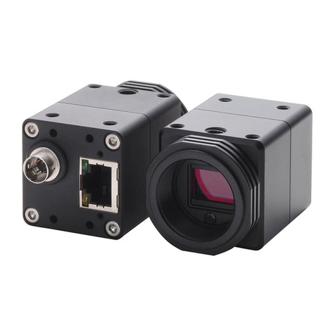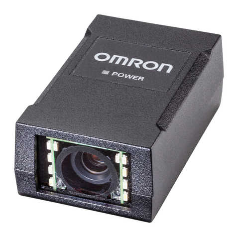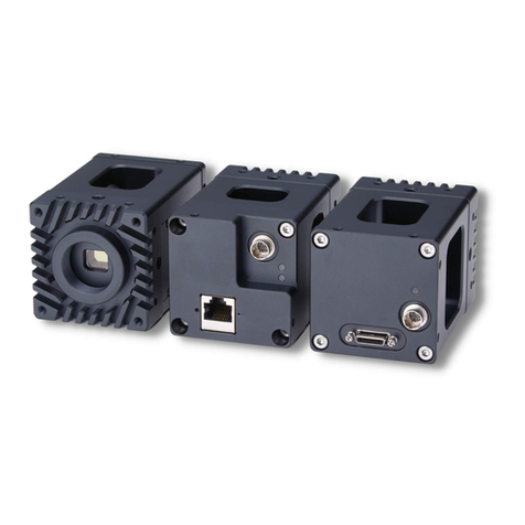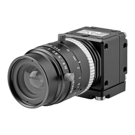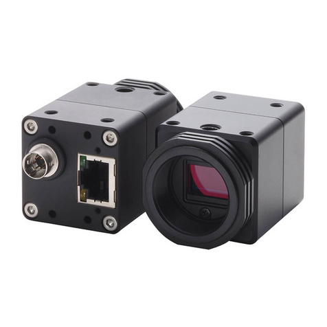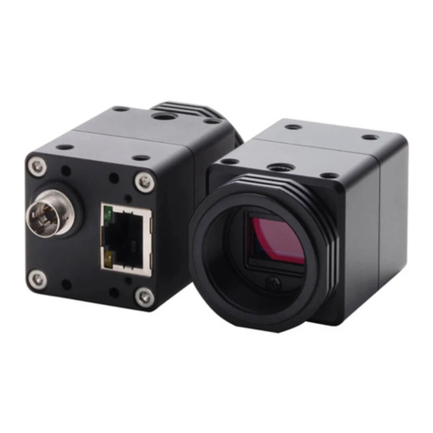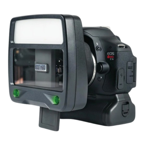
ImageSensorforFH-5MegapixelDigitalCamera
FH-SM05R/SC05R
Pleaseobservethefollowingprecautionstopreventfailuretooperate,
malfunction,orundesirableeffect.
1.Installationandstorageoftheproduct
Donotinstallinthefollowinglocations.
・Locationswheretheambienttemperatureexceedstherated
temperaturerange.
・Locationssubjecttosuddentemperaturechanges(where
condensationwillform).
・Locationswheretherearecorrosiveorflammablegases.
・Locationswherethereisdust,salt,orironpowder.
・Locationswherethedevicewillbesubjecttodirectvibrationor
shock.
・Locationswherethereisstrongscatteredlight.
・Locationsexposedtodirectsunlight
・Locationswherethereissplashingofwater,oil,orchemicals.
・Locationswherethereisastrongelectricalormagneticfield.
・Locationsclosetohigh-voltagedevicesand/orpowerdevices
2.Cables
・Whenconnectingordisconnectingthecameracableor
Camera-mountLightingcontrollercable,besuretoturnoffthe
controllerunit.
・Donotusethecameracableexceedingthespecifiedlength.
・Uptothreecameracablescanbeconnectedusingtheextensionunit
FZ-VSJ.Besuretousetherecommendedcameracablewith
FZ-VSJ.
・Whenconnectingthecameracable,tightenthecablewiththefixing
screwwiththerecommendedtorque(0.15N・m).Applyingexcessive
forcetothecameraconnectormaycausefailureoftheproduct.
・UsetheferritecoreequivalenttoZCAT2035-0930A(manufactured
byTDK)atthecontrollersideofthecameracable.(exceptforFH-L
series)
・ThecameracableFZ-VS□□haspolarity.Besuretoconnectthe
sidewiththenameplateonittothecontroller.Besuretoconnect
thesidewiththenameplateonittothecontroller.
3.Mounting
Thecameracaseisconnectedtothe0Vlineoftheinternalcircuit.
Observethefollowingprecautionstopreventnoisefromentering
thecamera.
・Donotgroundthecameraunit.
・Besuretouseabaseforinstallation.Whenmountingabase,engage
itwiththescrew(M4)withtherecommendedtorque(1.2N・m).
4.Beam
・Thebeamcentermayvaryforeachcamera.Besuretoconfirmthe
centerpositionoftheimageusingthemonitorbeforemounting.In
thenatureofthematerialsused,thebeamcenterofthisproduct
maychangeforthenumberofpixelsduetochangesinambient
temperature.
5.Maintenance
・Avoidusingthinner,alcohol,benzene,acetoneorkerosenetoclean
theproduct.
・Ifthereislargedirtordustattachedtotheimagingelement,blow
themoffwithblowerbrush(forcameralens).Donotuseyourbreath
toblowthedustoff.
・Whenthelensisnotmounted,besuretoattachtheC-mountcapon
thelensmount.Ifdirtordustisattachedtotheimageelements,
falsedetectionorfailuremayoccur.
・Besuretoattachaconnectorcaponunusedconnectorsattheback
ofthecamera.Removingtheconnectorcapmaycauseaforeign
materialenteringinthecamera,causingfalseoperationorfailure.
・Donotconnectdevicestotheextensionconnectorotherthanthe
dedicatedones(FL-TCC1orFLV-TCC□).
6.Imagingelement
・Inthenatureofimagingelement,linesmayappearinimagesdueto
measurementconditionsorsensitivities.Thisdoesnotindicateda
malfunction.Althoughtheremaybemultiplefaultypixels,thisdoes
notindicateamalfunction.Iftheseconditionsaffectmeasurementor
inspection,usetheCCDcamera.
This product is not designed or rated for ensuring safety
of persons. Do not use it for such purposes.
Meaning of Alert Symbols
Alert statements
INSTRUCTION SHEET
Thank you for selecting OMRON product. This sheet pri-
marily describes precautions required in installing and
operating the product.
Before operating the product, read the sheet thoroughly to
acquire sufficient knowledge of the product. For your con-
venience, keep the sheet at your disposal.
Model
WARNING
PRECAUTIONS ON SAFETY
PRECAUTIONS FOR SAFE USE
■Dimensions
© OMRON Corporation 2015 All Rights Reserved.
(Unit:mm)
Indicates a potentially hazardous situation which, if
not avoided, will result in minor or moderate injury,
or may result in serious injury or death. Additionally
there may be significant property damage.
WARNING
NOTICE:
This product meets CISPR11 class A. The intended use of this product is in an
industrial environment only.
Item
Model
Item Model
10 to 150Hz: half-amplitude: 0.35mm:(maximum acceleration: 50m/s
2
),
10 times for 8 minutes each in 3 directions
Shock resistance 150m/s2; 3 times each in 6 directions
Operating and storage: 35% to 85%
(with no condensation)
No corrosive gases
X, Y : ±0.31mm
∂x, ∂y : ±2.1°
Operating: 0 to 40 ℃(with no icing nor condensation)
Storage: -25 to 65 ℃ (with no icing nor condensation)
Powerconsumption
Vibration
resistance
Shock resistance
Ambient
Temperature
Ambient
humidity
Ambient
environment
Center positional
accuracy of
optical axis
Materials
Accessories
Degree of
protection IEC60529 IP40 (in-panel)
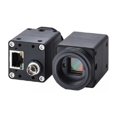
Camera cable
FZ-VS□□
Name plate
Enhancing connetor
Camera cable
connector
Picture element
Effective pixels
Pixel size
Video output
Gain
Lens mounting
*
Digital (8 bits)
C mount(Recommended: 3Z4S-LE SV-H series)
■Ratings / Performance
1.2 W max. (13 VDC)
Case: Aluminum
Camera base: PC/ABS
Mount screw: brass
●General specifications
FH-SM05R
FH-SC05R
Instruction Sheet (this sheet)
Using FZ-VS4/VSL4: 15 m max.
Using a dedicated product other than
FZ-VS4/VSL4: 10 m max.
Cable length
Weight Approx. 60 g (including base)
Exposure time
Scanning method
Frame rate
Synchronization method
●Performance specifications
■Connecting
* The camera cable FZ-VS□□ has polarity. Be sure to connect the side
with the name plate on it to the controller.
2592(H)×1944V)
1/2.5-inch color CMOS
2.2(μm)×2.2(μm)
Progressive
Shutter Rollingshutter
14fps
Internal
0to+20dB
500us〜100,000us (by50usunit)
FH-SC05R FH-SM05R
1/2.5-inch monochrome
CMOS
* The base at the bottom of the camera can be mounted to the bottom, top,
and both sides. Remove the base mounting screw (M2x7) and correct the
mounting position. (Recommended mounting screw torque: 0.32 N・m)
Using the Camera cable FZ-VS□□(sold separately), connect the connector
on the back of the camera and the camera connector on Controller FH series.
Besuretorespectfollowingitemsforsafety.
・Tightenallscrewssecurelyduringinstallation.
・DonotconnecttheSensortotheproductsotherthanthededicated
cameracable(FZ-VS□□),controller(FH),Camera-mount
Lightingcontroller(FL-TCC1andFLV-TCC□),extensionunit
(FZ-VSJ).IftheSensorisconnectedtonon-dedicatedproductsand
turnedthepoweron,thedevicesmaybedamagedandbeheatedtoa
hightemperature.Donotputanimpossiblestressonthecamera
cablewhenyousetitup.Thecableisdisconnected,anditbecomes
impossiblemightdoanormalmeasurement.
・Ifyoususpectanerrorormalfunction,stopusingtheController
immediately,turnOFFthepowersupply,andconsultyourOMRON
representative.
・Donottrytodisassemble,repair,ormodifytheproduct.
・Besuretodisposeoftheproductasindustrialwaste.
・Donotputanimpossiblestressonthecameracablewhenyousetit
up.Thecableisdisconnected,anditbecomesimpossiblemightdoa
normalmeasurement.
*For optical diagrams, refer to FH manual or catalog.
OPTICALAXIS
PRECAUTIONS FOR CORRECT USE
MOUNTINGSCREWHOLES
TRACEABILITY INFORMATION:
Importer in EU:
Omron Europe B.V.
Wegalaan 67-69
2132 JD Hoofddorp,
The Netherlands
2-
4.5
19±0.1
28
28
6.5
24
1"-32UN-2A(CMOUNT)
12
14.5
22
40
7.3
11
20.5
3-M2DEPTH3.0(BOTHSIDE)
14.5
12
22
3-M2DEPTH3.0
5.5
33.5
10.5
9.59.5
1/4-20UNCDEPTH5.5
2-M4DEPTH5.5
19.4
7.9
5.4
Suitability for Use
Suitability for Use
s
Omron Companies shall not be responsible for conformity with any standards,
codes or regulations which apply to the combination of the Product in the
Buyer’s application or use of the Product. At Buyer’s request, Omron will
provide applicable third party certification documents identifying ratings and
limitations of use which apply to the Product. This information by itself is not
sufficient for a complete determination of the suitability of the Product in
combination with the end product, machine, system, or other application or
use. Buyer shall be solely responsible for determining appropriateness of the
particular Product with respect to Buyer’s application, product or system.
Buyer shall take application responsibility in all cases.
NEVER USE THE PRODUCT FOR AN APPLICATION INVOLVING
SERIOUS RISK TO LIFE OR PROPERTY WITHOUT ENSURING THAT THE
SYSTEM AS A WHOLE HAS BEEN DESIGNED TO ADDRESS THE RISKS,
AND THAT THE OMRON PRODUCT(S) IS PROPERLY RATED AND
INSTALLED FOR THE INTENDED USE WITHIN THE OVERALL
EQUIPMENT OR SYSTEM.
See also Product catalog for Warranty and Limitation of Liability.
Oct, 2014
D
OMRON Corporation Industrial Automation Company
Contact: www.ia.omron.com
Tokyo, JAPAN
OMRON ELECTRONICS LLC
2895 Greenspoint Parkway, Suite 200
Hoffman Estates, IL 60169 U.S.A.
Tel: (1) 847-843-7900/Fax: (1) 847-843-7787
OMRON ASIA PACIFIC PTE. LTD.
No. 438A Alexandra Road # 05-05/08 (Lobby 2),
Alexandra Technopark,
Singapore 119967
Tel: (65) 6835-3011/Fax: (65) 6835-2711
OMRON (CHINA) CO., LTD.
Room 2211, Bank of China Tower,
200 Yin Cheng Zhong Road,
PuDong New Area, Shanghai, 200120, China
Tel: (86) 21-5037-2222/Fax: (86) 21-5037-2200
OMRON EUROPE B.V.
Sensor Business Unit
Carl-Benz-Str. 4, D-71154 Nufringen, Germany
Tel: (49) 7032-811-0/Fax: (49) 7032-811-199
Regional Headquarters
