EM-Technik 2D Series User manual
EM-Technik GmbH - Industriestraße 2 - 67133 Maxdorf - Germany
1
Pipe Connectors 2D
Operating and Installation Instructions
EN

EM-Technik GmbH - Industriestraße 2 - 67133 Maxdorf - Germany
2
1 General information .............................................................................................................................................. 3
1.1 Introduction...................................................................................................................................................... 3
1.2 Warnings ......................................................................................................................................................... 3
1.3 Special Hazards .............................................................................................................................................. 3
1.4 General Safety Instructions ............................................................................................................................. 3
1.5 Designated Use............................................................................................................................................... 3
1.6 Reasonably Foreseeable Misuse .................................................................................................................... 3
2 Manufacturer’sSpecication ............................................................................................................................. 4
2.1 Description ...................................................................................................................................................... 4
2.2 Transport and Storage..................................................................................................................................... 4
3 Technical Data ..................................................................................................................................................... 4
3.1 Dimensions...................................................................................................................................................... 4
3.2 Operating Medium........................................................................................................................................... 4
3.3 Pressure Guide ............................................................................................................................................... 4
3.4 Connecting Guide............................................................................................................................................ 4
4 Assembly and Operation .................................................................................................................................... 4
4.1 Assembly Instructions...................................................................................................................................... 4
4.2 Tools Required ................................................................................................................................................ 4
4.3 Connect Thread Side ...................................................................................................................................... 5
4.4 Torque Chart.................................................................................................................................................... 5
4.5 Connecting Pipe Side...................................................................................................................................... 5
4.6 Fastening Options ........................................................................................................................................... 5
5 Commissioning ................................................................................................................................................... 5
5.1 Precondition for Commissioning...................................................................................................................... 5
6 Maintenance......................................................................................................................................................... 5
7 Disposal ............................................................................................................................................................... 5
8 Return Delivery.................................................................................................................................................... 6
9 Troubleshooting/FaultRectication ................................................................................................................ 6
10 Manufacturer‘s Declaration ................................................................................................................................ 6
11 Contact ................................................................................................................................................................. 6
Contents
EM-Technik GmbH - Industriestraße 2 - 67133 Maxdorf - Germany
3
1. General information
1.1 Introduction
• These instructions apply to series 2D pipe connectors,
also referred to below as connectors.
• Read the instructions completely before using our pro-
ducts to prevent injuries, material damage and mal-
functions!
• Save the instructions for later reference.
• All rights including copyright and industrial property
rights are explicitly reserved.
1.2 Warnings
• Warnings are always identied by a signal word. The
following signal words or hazard levels are used:
Danger: Failure to follow instructions will
lead to serious injuries or death. High risk le-
vel of endangerment.
Warning: Failure to follow instructions may
lead to serious injuries or death. Moderate
risk level of endangerment.
Caution: May lead to slight or moderate inju-
ries. Low risk level of endangerment.
Note: Refers to an instruction that must ab-
solutely be followed.
Information: Gives useful tips and recom-
mendations..
1.3 Special Hazards
• It must be ensured that the connector is resistant for
the media and temperatures that will be used. The re-
sistance of the connector with aggressive media de-
pends in individual cases on many variables (such as
the temperature, concentration ratio of the medium,
material, environment, pipe material etc.). The person
ordering the connector is responsible for checking for
the specic application. In case of doubt install the con-
nector on a trial basis.
• Always comply with the safety data sheets or the safety
requirements for the media you are using!
• Before removing the connector it must be ensured that
there is no more medium in the exible pipe system
and the pressure has completely dissipated. Exercise
caution for toxic, corrosive or hot media residue owing
out of the line or remaining in dead spaces.
1.4 General Safety Instructions
• The connector must be properly connected to the pipe
system.
• Before installing the connector make certain that ex-
ternal mechanical eects such as thrust and bending
forces are not acting on the pipe system.
• Installation, commissioning, operation, installation,
maintenance, troubleshooting and disassembly must
only be performed by qualied specialists with due con-
sideration of accident prevention regulations. Person-
nel must be capable based on their technical training
and experience of performing assembly tasks, follo-
wing technical specications and recognizing possible
dangers.
• Personnel with decient knowledge must be trained
and instructed.
• Areas of responsibility and responsibilities must be pre-
cisely regulated and personnel must be monitored.
These safety instructions do not take into consideration
any:
• Coincidences and events that could occur at the cus-
tomer location during assembly, operation and mainte-
nance.
• Local safety requirements, for which the operating
company is responsible to ensure compliance, inclu-
ding assembly personnel who are used.
1.5 Designated Use
• The connector must only be operated within the permit-
ted usage ranges for pressure and temperature.
• Only the operating media named in the documentation
are permitted to ow through the connector.
• The connector must only be operated if it is in awless
technical condition.
• The connector must not be operated if it is in partially
assembled condition.
• If other operating modes are not named in the docu-
mentation, they must be approved with the manufac-
turer.
1.6 Reasonably Foreseeable Misuse
• Any usage other than designated use.
• Do not make any modications to the product by your-
self!
• Components should only be retrotted after consulta-
tion with the manufacturer.
EM-Technik GmbH - Industriestraße 2 - 67133 Maxdorf - Germany
4
2Manufacturer’sSpecication
2.1 Description
The pipe connector series 2D is used to securely connect
pipes.
2.2 Transport and Storage
• The connector must be protected against mechanical
damage, moisture, dirt and dust. The storage tempera-
ture range is 10 – 40°C.
• Avoid UV radiation and direct sunlight.
• Leave the connector in its original packaging to ensure
the best possible protection.
• Dispose of the packaging material according to dispo-
sal requirements/environmental protection regulations.
3 Technical Data
3.1 Dimensions
The exact dimensions of the pipe connector can be
found on our homepage under the following link:
www.em-technik.com
3.2 Operating Medium
• Gaseous and liquid media that do not negatively aect
the physical and chemical properties of the relevant
housing and sealing material.
• If you have questions about resistance please contact
emtechnik.
• For the maximum permitted operating pressure/tempe-
rature see the pressure guide.
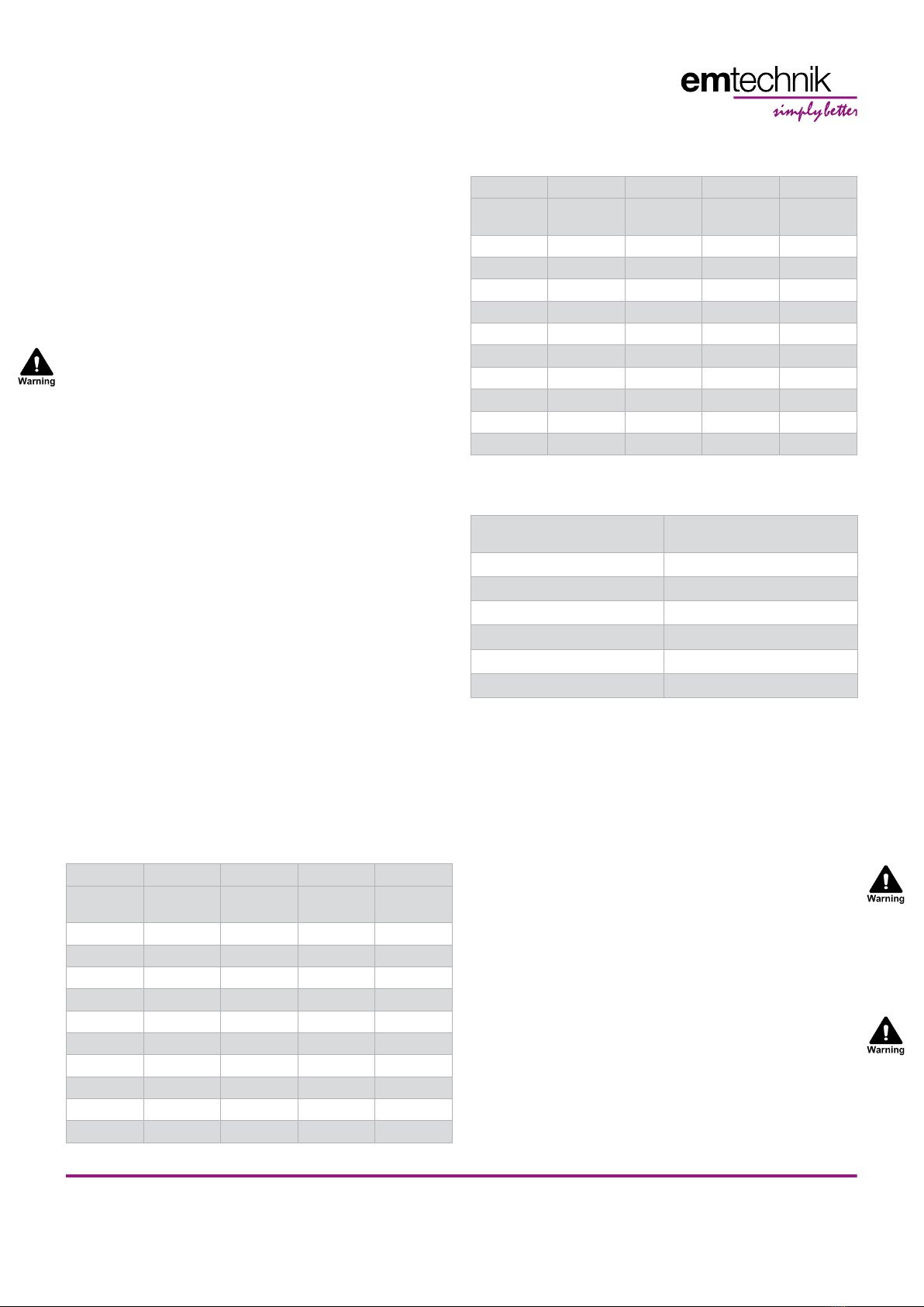
3.3 Pressure Guide
As the temperature rises, the eectiveness of the con-
nector falls, as shown by this table.
Material PP PVDF PTFE PFA
Pressure
Stage PN 10 PN 10 PN 6 PN 10
-40°C 75% 75% 75%
-20°C 100% 100% 100%
5°C 100% 100% 100% 100%
20°C 100% 100% 100% 100%
30°C 80% 80% 80% 90%
40°C 70% 70% 70% 85%
50°C 60% 60% 60% 80%
60°C 50% 50% 50% 70%
70°C 40% 45% 40% 60%
80°C 30% 40% 30% 50%
Material PP PVDF PTFE PFA
Pressure
Stage PN 10 PN 10 PN 6 PN 10
90°C 20% 35% 30% 40%
100°C 35% 30% 40%
110°C 30% 25% 35%
120°C 25% 25% 30%
130°C 25% 25% 30%
140°C 10% 20% 25%
150°C 10% 20%
160°C 15%
170°C 10%
180°C 10%
3.4 Connecting Guide
The connector 2D is suitable for following pipes:
Pipe Material Recommended 2D Material
(depending on medium)
Glass pipes PVDF PFA PTFE
Metal pipes PP PVDF
PA (pipe) PP
PE (HD) PP PVDF PFA
PFA (pipe) PVDF PFA PTFE
PVDF (pipe) PVDF PTFE
4 Assembly and Operation
4.1 Assembly Instructions
• Make certain the connector is suitable for the relevant
application. The connector must be suitable for the
operating conditions of the pipeline system (medium,
concentration, temperature and pressure) as well as
the relevant ambient conditions.
• Check the connector for transport damage before in-
stalling it. If the connector is damaged do not install it.
• The planner, the construction company or operating
company are responsible for the positioning and ins-
tallation of the connector. Planning and installation er-
rors can adversely aect the reliable functionality of the
connector and may represent a signicant potential for
hazard.
• After the connector is installed perform a tightness and
function check.
4.2 Tools Required
The tools required for installation and assembly are not
included with delivery.
EM-Technik GmbH - Industriestraße 2 - 67133 Maxdorf - Germany
5
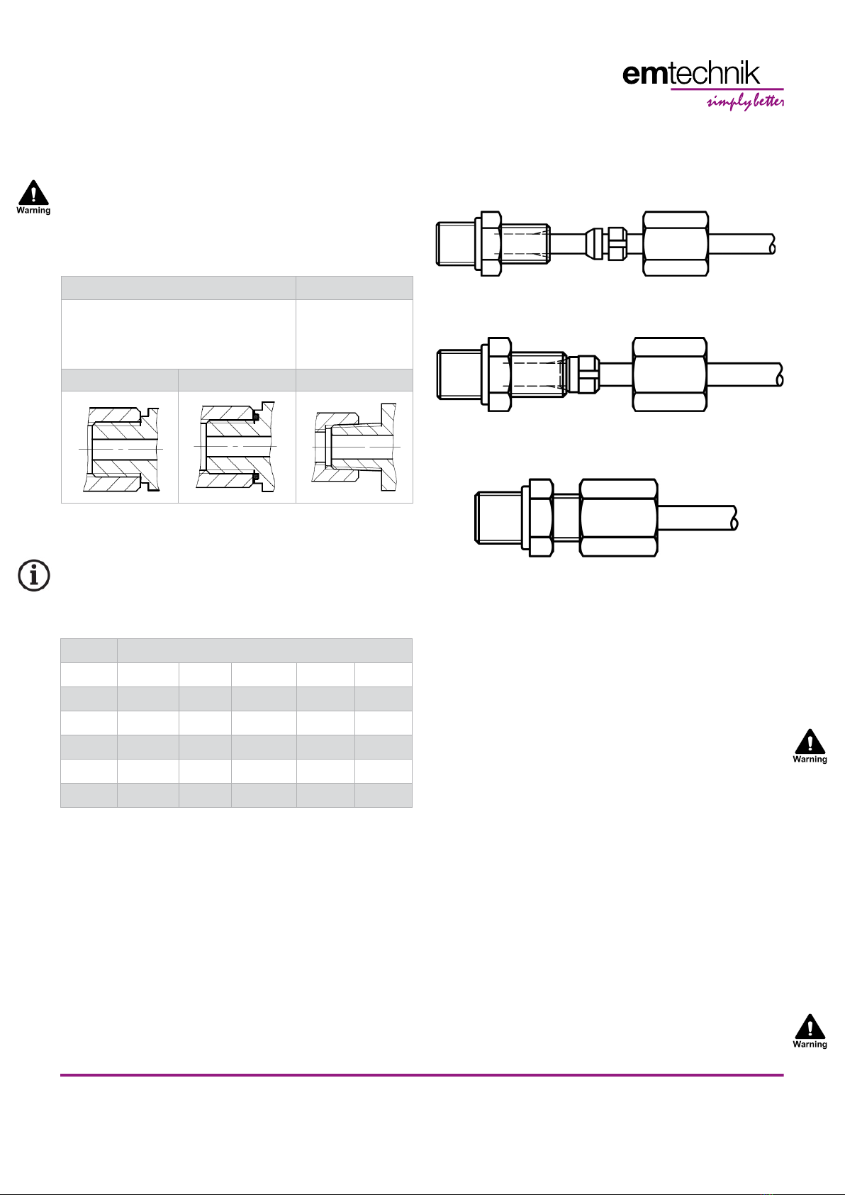
4.3 Connect Thread Side
• The connector must be connected to the pipeline so it
is free of mechanical stress.
• The connector can have a male or female thread (ISO,
DIN, ANSI) and can be connected with various connec-
ting elements of the emtechnik system.
Cylindrical thread Conical thread
Sealing is provided by a sealing collar for
Cylindrical threads (G, M or UNF).
A version with an O-ring is also possible.
Sealing is provided
by the thread itself
for Conical threads
(NPT).
Sealing Collar O-Ring Thread
• Each thread must always be connected with the same
thread type.
• If a plastic connector is used in combination with a me-
tallic male tting, additional sealing with Teon® tape is
recommended.
4.4 Tightening torques for G-thread
Plastic Thread
G 1/8“ G 1/4“ G 3/8“ G 1/2“ G 3/4“
PP 1,0 Nm 1,5 Nm 4,0 Nm 4,0 Nm 4,0 Nm
PVDF 1,0 Nm 1,5 Nm 4,0 Nm 4,0 Nm 4,0 Nm
PFA 60° 60° 60° 45° 30°
PTFE 60° 60° 60° 45° 30°
PEEK on request on request on request on request on request
All data in Nm; Angle of rotation from contact with the sealing surface
4.5 Connecting Pipe Side
Regard the following steps when mounting the pipe con-
nectors:
• Cut o the pipe in a right angle.
• Push the nut, the cutting ring and the sealing ring over
the end of the pipe.
Connector Body Sealing
Ring
Cutting
RIng
Nut Pipe
• Push the end of the pipe through the connector.
• Screw on the nut by hand and tighten carefully with an
open-ended spanner.
4.6 Fastening Options
For the connectors are no fastening options intended.
5 Commissioning
5.1 Precondition for Commissioning
• Protect against leaks: Take protective measures
against exceeding the maximum permitted pressure
due to possible pressure surges.
• Check the tightness and function of the connector.
• In new systems and after repairs, ush the line system
to remove foreign materials.
6 Maintenance
• When used as designated, the connector is practically
wear-free and generally requires no maintenance.
• The operating company must perform regular visual
inspections of the connector according to the operating
conditions to prevent leaks and damage.
7 Disposal
• When disposing of the connector and packaging,
comply with the relevant disposal requirements and
environmental protection regulations.
• When disposing of connector, pay careful attention to
any residues of toxic or corrosive media.

EM-Technik GmbH - Industriestraße 2 - 67133 Maxdorf - Germany
6
8 Return Delivery
Do not return before consulting with emtechnik.
1. Please consult with emtechnik.
2. Empty the connector properly.
3. Rinse and clean the connector thoroughly, especially
if the media is being conveyed are harmful, explosive,
hot, or hazardous in some other way.
4. For connectors that have been operated with aggres-
sive, corrosive, combustible, toxic or water polluting
media, a completely lled in clearance certicate must
always be included.
9 Troubleshooting / Fault
Rectication
Error Possible Cause ErrorRectication
Connection
between thread side
and system leaking
Sealing surface is
damaged
Use sealant, see 4.3
Pipe connection is
leaking
Pipe is not correct
mounted
Mount connector
correctly, see 4.5
No ow Connector is blocked Clean the connector
or replace it
10 Manufacturer‘s Declaration
• Our products do not fall under the scope of the Ma-
chinery Directive 2006/42/EC. However, they can be
incorporated in an installation that is considered as
machinery. In this case regard the following note: The
products may not be put into operation until it is made
sure that the nal machinery into which our products
are incorporated complies with the provisions of the
Machinery Directive 2006/42/EC.
• Based on the uid class, pressure and nominal diame-
ter, our products fall under diagram 8 of the Pressure
Equipment Directive PED 2014/68/EU. Because of the
ratio of nominal diameter, pressure and volume, they
fall only under article 4 paragraph 3 and are designed
and manufactured according to applicable good engi-
neering practice. They must not carry any CE marking.
• The warranty of armature expires in the following ca-
ses: Operating conditions which do not follow the in-
tended use or do not follow technical specications.
Improper installation or assembly. Just as well as inap-
propriate use, dismantling or modication.
• Failure to observe information provided here may lead
to injuries, material damage, malfunctions and impuri-
ties due to escaping medium
11 Contact
If you have questions or suggestions please contact us at:
EM-Technik GmbH
Industriestr. 2 Tel +49 6237 407-0
67133 Maxdorf Fax +49 6237 407-77
Germany [email protected]
Version 01/2023
Table of contents
Other EM-Technik Cables And Connectors manuals


Popular Cables And Connectors manuals by other brands


Volkswagen
Volkswagen VAS 5581/15 operating manual

BERNSTEIN
BERNSTEIN SEU-1/0-T45 Series instruction manual

Tektronix
Tektronix Keithley 237-ALG-2 quick start guide

TE Connectivity
TE Connectivity Quadrax DSub Application Specification

TE Connectivity
TE Connectivity Miniature AMP-IN Application Specification

HP
HP StorageWorks SN6000 Quickstart installation instructions


