manuals.online logo
Brands
  1. Home
  2. •
  3. Brands
  4. •
  5. TE Connectivity
  6. •
  7. Cables And Connectors
  8. •
  9. TE Connectivity Miniature AMP-IN User guide

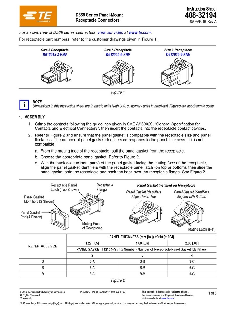
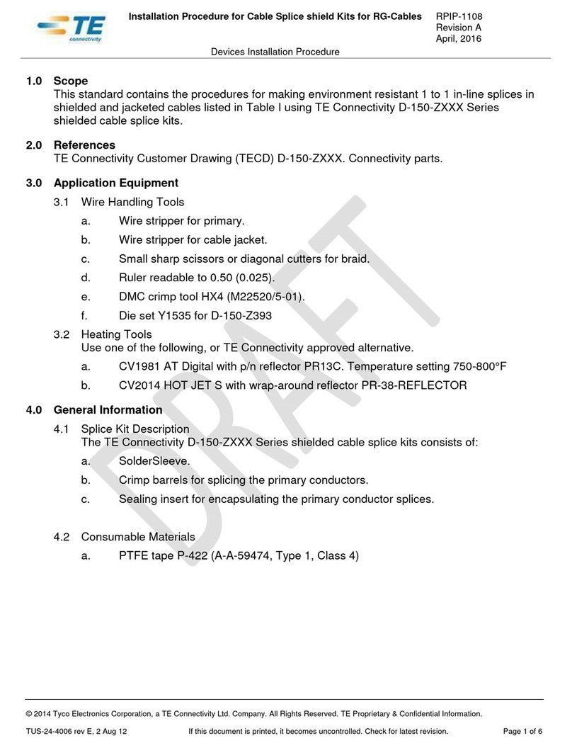
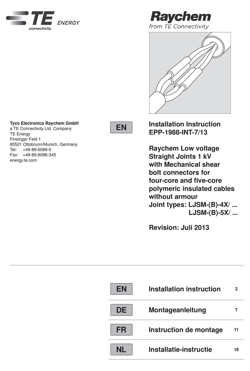
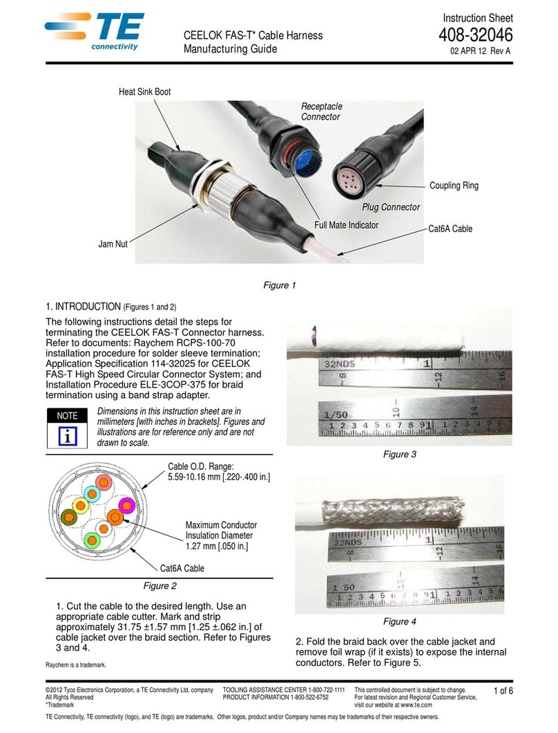
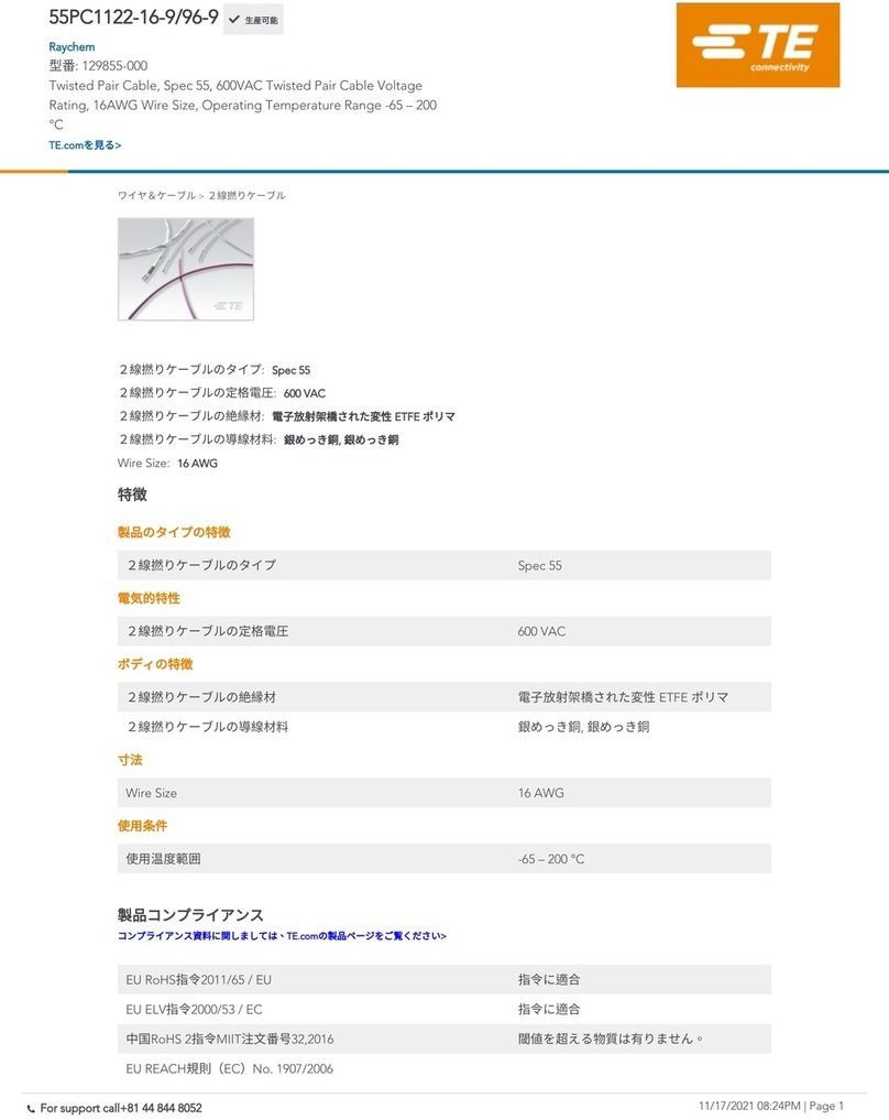
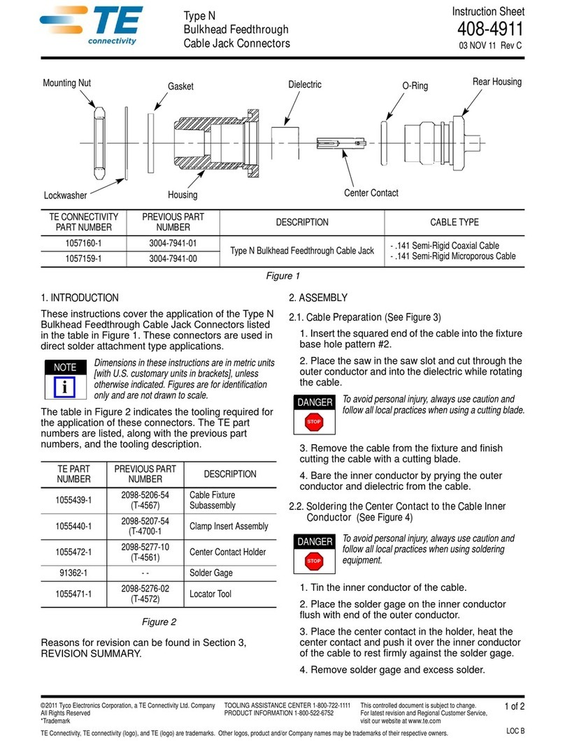
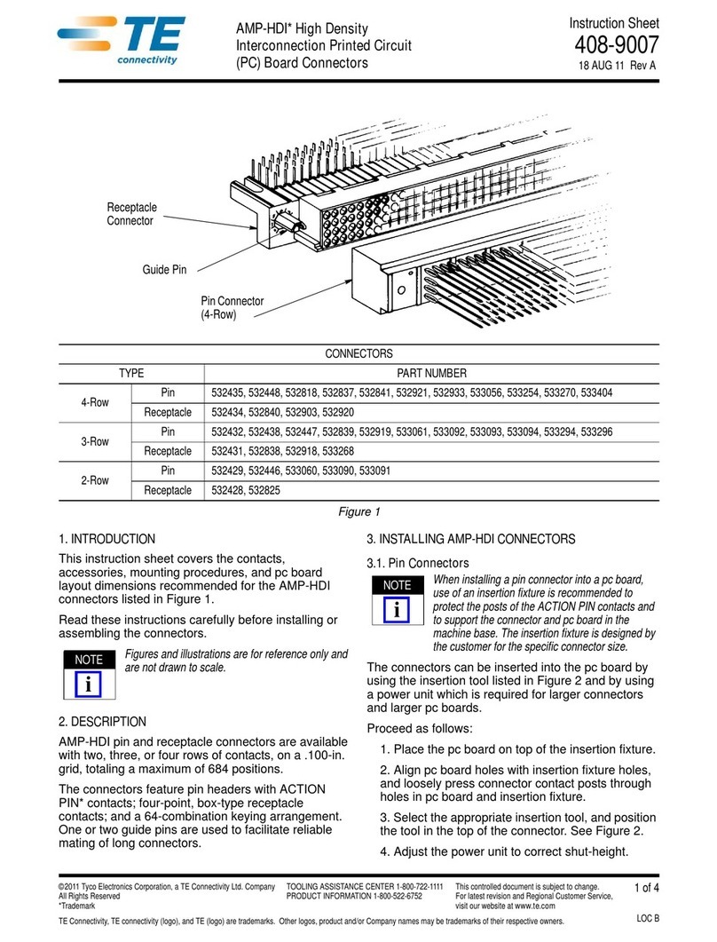
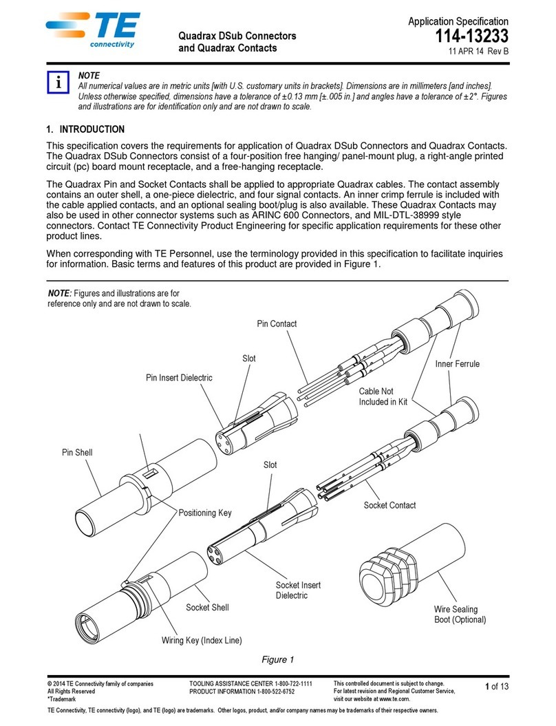
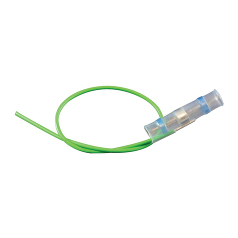
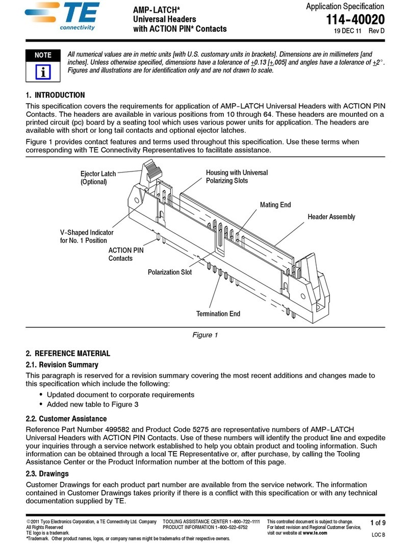
TE Connectivity Miniature AMP-IN User guide

NOTE
i
Application Specification
©2012 Tyco Electronics Corporation, a TE Connectivity Ltd. company
All Rights Reserved
*Trademark
TE Connectivity, TE connectivity (logo), and TE (logo) are trademarks. Other logos, product and/or company names may be trademarks of their respective owners.
1of 8
TOOLING ASSISTANCE CENTER
1-800-722-1111
PRODUCT INFORMATION
1-800-522-6752
This controlled document is subject to change.
For latest revision and Regional Customer Service,
visit our website at www.te.com
114-1016
Miniature AMP-IN* Contacts and
Miniature AMP-IN 2000 Contacts 16 OCT 12 Rev EE
Allnumerical valuesare inmetric units[withU.S.customary unitsinbrackets]. Dimensionsare inmillimeters [andinches].
Unless otherwise specified, dimensions have a tolerance of ±0.13 [±.005] and angles have a tolerance of ±2°. Figures
and illustrations are for identification only and are not drawn to scale.
1. INTRODUCTION
This specification covers the requirements for application of miniature AMP-IN contacts and miniature AMP-IN
2000 contacts. These contacts are designed to hold the strands of wire together so that the wire can be inserted
into holes in a printed circuit (pc) board.
Each contact features a wire barrel, insulation barrel, locking lance(s), and stabilizer barrel or insulation stop/
positive board stop. The locking lance is designed to prevents the contact from backing out of the pc board hole.
The stabilizer barrel holds the contact steady during the soldering process, and the insulation stop/positive
board stop prevents the wire insulation from being inserted and the contact from being over inserted into the pc
board hole. These requirements are applicable to automatic termination machines.
When corresponding with personnel, use the terminology provided in this specification to facilitate your inquiries
for information. Basic terms and features of this product are provided in Figure 1.
Miniature AMP-IN Contact Miniature AMP-IN 2000 Contact
Insulation Stop/
Positive Board Stop
Locking Lance
Wire Barrel
Insulation
Barrel
Wire Barrel
Insulation
Barrel
Stabilizer
Barrel
Locking Lance
(2 Places)
Figure 1
2. REFERENCE MATERIAL
2.1. Revision Summary
Revisions to this application specification include:
•Corrected inch conversion for pc board thickness in Paragraph 3.4
2.2. Customer Assistance
Reference Product Base Part Numbers 640401 and 794121 and Product Code 1326 are representative of
miniature AMP-IN contacts and miniature AMP-IN 2000 contacts. Use of these numbers will identify the product
line and help you to obtain product and tooling information. Such information can be obtained through a local
Representative, by visiting our website at www.te.com, or by calling PRODUCT INFORMATION or the
TOOLING ASSISTANCE CENTER at the numbers at the bottom of this page.
2.3. Drawings
Customer Drawings for specific products are available from the responsible Engineering Department via the
service network. The information contained in the Customer Drawings takes priority if there is a conflict with this
specification or with any other technical documentation supplied.
114-1016
2of 8
Rev EE
2.4. Manuals
Manual 402-40 can be used as a guide to soldering. This manual provides information on various flux types and
characteristics with the commercial designation, flux removal procedures, and a guide for information on
soldering problems.
2.5. Specifications
Product Specification 108-1081 provides product performance and test information.
2.6. Instructional Material
Instruction Sheets (408-series) provide product assembly instructions or tooling setup and operation procedures
and Customer Manuals (409-series) provide machine setup and operating procedures. Documents available
that pertain to this product are:
408-8040 Heavy Duty Miniature Quick-Change Applicators with Mechanical Feed System
408-9640 Crimp Quality Monitor (CQM) Applicators for Side-Feed and End-Feed Applications
409-5128 AMP-O-LECTRIC* Model “K" Terminating Machine (Obsolete)
409-5842 AMP-O-LECTRIC Model “G" Terminating Machine
409-5866 AMPOMATOR* CLS IV Lead-Making Machine
3. REQUIREMENTS
3.1. Safety
Do not stack product shipping containers so high that the containers buckle or deform.
3.2. Wire Selection and Preparation
The contacts accept stranded wire sizes 26 to 10 AWG with an insulation diameter range given in Figure 2.
Wire strip length shall be as given in Figure 2.
!
CAUTION
Care shall be taken during the stripping operation to ensurethe conductor is not nicked, scraped, or cut.
3.3. Crimp Requirements
The contacts must be crimped according to the instructions packaged with the machine.
!
CAUTION
Care shall be taken to ensure that the wire insulation is not cut or broken during the crimping operation and ensure that
the insulation is not crimped into the wire barrel nor the stabilizer barrel.
A. Crimp Height and Width
The wire barrel, insulation barrel, and stabilizer barrel crimp height and width must not exceed the dimensions
given in Figure 3.
B. Stabilizer Barrel
The stabilizer barrel seam may be open only if the contact is crimped to wire sizes 10 or 12 AWG.
The stabilizer barrel can have an F-crimp or “O” crimp.
C. Insulation Stop/Positive Board Stop
The insulation stop/positive board stop must not be terminated; it must remain in the open U shape.
D. Wire Barrel Seam
The wire barrel seam can be closed or slightly open, but shall have no wire strands protruding from the seam.
E. Wire Barrel Flash
The wire barrel flash must be no more than the dimension given in Figure 3.
Strip Length (See Table)
Miniature
AMP-IN
350566 22-18 1.52-2.79 [.060-.110] 4.51 [.178]
640108 26-22 1.52-2.54 [.060-.100]
640311 22-18 1.52-2.79 [.060-.110] 4.83 [.190]
640401 26-22 1.02-2.54 [.040-.100]
640663 26-22 1.02-1.78 [.040-.070] 4.51 [.178]
770060 18-14 2.29-3.81 [.090-.150] 5.21 [.205]
770565 22-18 1.52-2.79 [.060-.110] 4.33 [.170]
794013 12 2.29-3.81 [.090-.150] 5.21 [.205]
794037 12-10 5.08 [.200] Max
Miniature
AMP-IN 2000 794121 22-18 1.27-2.79 [.050-.110] 5.08 [.200]
794122 26-22 1.27-2.79 [.050-.110]
114-1016
3of 8
Rev EE
Figure 2
Miniature AMP-IN Contact
0.64 [.025] Min
Locking Lance Height
Wire Conductors and Insulation
Both Visible Between Wire
Barrel and Insulation Barrel
0.25 [.010]
Rear Bellmouth
0.38 [.015] Max
End of Wire
Conductor to
Wire Barrel
X
X
Miniature AMP-IN 2000 Contact
X
X
See Detail A See Detail A
Wire Insulation Not Crimped in Stabilizer Barrel
WireConductorsandInsulationVisible
Between Insulation Barrel and
Insulation Stop/Positive Board Stop
Y
Y
Y
Y
3.56 [.140] Min
Between
Locking Lances
0.08 [.003]
Wire Barrel Flash
Wire Barrel Seam
Closed (or Can Be
Slighty Open) with
No Strands Visible
Section X-X Detail A 0.08 [.003]
Max Burr
0.38
[.015] Max
Cutoff Tab
WireBarrelorStabilizerBarrel
Crimp Height
Wire Barrel or
StabilizerBarrelCrimp
Width
Section Y-Y
Insulation Barrel Crimp
Width
StabilizerBarrelCanHave
F-Crimp or “O” Crimp
Wire
Barrel Insulation
Barrel
Stabilizer
Barrel
Wire
Barrel Insulation
Barrel
Figure 3 (Cont’d)
CONTACT WIRE
TYPE BASE PART NUMBER SIZE (AWG) INSULATION DIAMETER STRIP LENGTH
(±0.38 [±0.15])
Miniature
AMP-IN
350566 22-18 1.07 [.042] 1.57 [.062] — —
2.79 [.110]
640108 26 0.81 [.032] 1.07 [.042] — —24 0.86 [.034]
22 0.96 [.038]
640311 22-20 0.76 [.030] 1.57 [.062] 1.40±0.05
[.055±.002] 1.57 [.062]
18 0.94 [.037]
640401 26-24 0.74 [.029] 1.07 [.042] 1.02±0.05
[.040±.002] 1.07 [.042]
22 0.89 [.035]
640663 26 0.81 [.032] 1.07 [.042] — — 1.78 [.070]24 0.86 [.034]
22 0.96 [.038]
770060 18-16 1.09 [.043] 2.79 [.110]
2.40±0.10
[.094±.004] 2.79+0.13/-0.00
[.110+.005/-.000] 3.94 [.155]
14 1.40 [.055] 2.75±0.10
[.108±.004]
770565 22 0.81 [.032] 1.57 [.062] — — 2.79 [.110]20 0.91 [.036]
18 1.07 [.042]
794013 12 2.16 [.085] 2.79 [.110] 2.79±0.05
[.110±.002] 2.79 [.110] 3.94 [.155]
794037 12 2.41 [.095] 2.79 [.110] 2.79+0.05
[.110+.002] 2.79 [.110] 5.33 [.210]
10 2.74 [.108] 3.56 [.140] 3.56 [.140]
Miniature
AMP-IN 2000
794121 22 0.76 [.030] 1.57 [.062] — —
3.30 [.130]
20 0.86 [.034]
18 0.91 [.036]
794122 26 0.71 [.028] 1.07 [.042] — —24 0.79 [.031]
22 0.86 [.034]
114-1016
4of 8
Rev EE
Figure 3 (End)
F. Cutoff Tab and Burr
The carrier strip cutoff tab and burr must be no more than the dimensions given in Figure 3.
G. Rear Bellmouth
The rear bellmouth length must be no more than the dimension given in Figure 3.
H. Wire Location
The wire conductor end shall be flush with the front end of the contact wire barrel or extend past the end of
the wire barrel no more than the dimension given in Figure 3.
For miniature AMP-IN contacts, the wire conductor and insulation should be visible between the insulation
barrel and the wire barrel or stabilizer barrel. The wire insulation should not be crimped into the stabilizer
barrel. For miniature AMP-IN 2000 contacts, the wire conductor and insulation should be visible between the
insulation barrel and insulation stop/positive board stop.
CONTACT
WIRESIZE
(AWG)
CONTACT
TYPE BASE PART
NUMBER
WIRE BARREL CRIMP STABILIZER BARREL CRIMP INSULATION
BARREL
CRIMP WIDTH
HEIGHT
(±0.05 [±.002]) WIDTH HEIGHT WIDTH
114-1016
5of 8
Rev EE
I. Locking Lance(s)
The locking lance(s) shall be set to within limits given in Figure 3.
3.4. PC Board
The pc board thickness shall be 0.157±0.18 [.062±.007]. The pc board hole size for the contact should be within
the tolerances specified in Figure 4.
Miniature
AMP-IN
350566 22-20 1.83±0.08 [.072±.003]
18 1.96±0.08 [.077±.003]
640108 26-22 1.40±0.10 [.055±.004]
640311 22-20 1.83±0.08 [.072±.003]
18 1.96±0.08 [.077±.003]
640401 26-22 1.40±0.10 [.055±.004]
640663 26-22 1.40±0.10 [.055±.004]
770060 18-14 3.18±0.08 [.125±.003]
770565 22-20 1.83±0.08 [.072±.003]
18 1.96±0.08 [.077±.003]
794013 12 3.18±0.08 [.125±.003]
794037 12 3.18±0.08 [.125±.003]
10 3.76±0.08 [.148±.003]
Miniature
AMP-IN 2000 794121 22-20 1.83±0.08 [.072±.003]
18 1.96±0.08 [.077±.003]
794122 26-22 1.40±0.10 [.055±.004]
Figure 4
3.5. Inserting Contact into PC Board Hole
The contact must be inserted into the pc board hole until the locking lance(s) are through the pc board hole.
For the miniature AMP-IN 2000contact, the insulation stop/positive board stop will prevent the contact from
being further inserted in the hole. See Figure 5.
Miniature AMP-IN Contact
Miniature AMP-IN 2000 Contact
LockingLancesThrough
PC Board Hole Locking Lance Through
PC Board Hole
Insulation Stop/
Positive Board Stop
Against PC Board (Ref)
Figure 5
CONTACT WIRE SIZE (AWG) PC BOARD HOLE SIZE
TYPE BASE PART NUMBER
Wave 260°C [500°F] (Wave Temperature) 5 Seconds
Vapor Phase 215°C [419°F] 5 Minutes
Infrared Reflow 230°C [446°F] 5 Minutes
114-1016
6of 8
Rev EE
3.6. Soldering
A. Process
The contacts can be soldered using wave soldering or equivalent soldering techniques. Temperature and
exposure time shall be as specified in Figure 6.
Figure 6
RMA Mild Noncorrosive 185/197 611
Center (Activated) Medium Corrosive or Noncorrosive 1544, 1545, 1547 711, 809, 811
B. Flux Selection
The contact wire barrel must be fluxed prior to soldering with a rosin base flux. Selection of the flux will
depend on the type of pc board and other components mounted on the board. Additionally, the flux must be
compatible with the wave solder line, manufacturing, health, and safety requirements. Call PRODUCT
INFORMATION at the number at the bottom of page 1 for consideration of other types of flux. Flux that is
compatible with these connectors are provided in Figure 7.
Figure 7
ALPHA 2110 Aqueous 1132°C [270°F]
BIOACT EC-7 Solvent 5100°C [212°F]
Butyl CARBITOL Solvent 1Ambient Room
Isopropyl Alcohol Solvent
5100°C [212°F]
KESTER 5778 Aqueous
KESTER 5779 Aqueous
LONCOTERGE 520 Aqueous
LONCOTERGE 530 Aqueous
Terpene Solvent
C. Cleaning
After soldering, removal of fluxes, residues, and activators is necessary. Consult with the supplier of the solder
and flux for recommended cleaning solvents. Cleaners must be free of dissolved flux and other contaminants.
It is recommended that cleaning takes place with the pc board on its edge. If using an aqueous cleaner, it is
recommended using standard equipment, such as a soak tank or automatic in-line machine. Common cleaning
solvents with times and temperatures that will not affect these contacts is specified in Figure 8.
Figure 8
ALPHA, BIOACT, CARBITOL, LONCOTERGE, and KESTER are trademarks of their respective owners.
D. Drying
When drying cleaned contacts and pc boards, temperature limitations must not be exceeded: -55° to 105°C
[-67° to 221°F]. Excessive temperatures may cause contact degradation.
4. QUALIFICATION
Miniature AMP-IN contacts and miniature AMP-IN 2000 contacts are not required to have outside agency approval.
SOLDERING PROCESS TEMPERATURE TIME (At Max Temperature)
FLUX TYPE ACTIVITY RESIDUE COMMERCIAL DESIGNATION
KESTER ALPHA
CLEANER TIME
(Minutes) TEMPERATURE
(Maximum)
NAME TYPE
114-1016
7of 8
Rev EE
5. TOOLING
Tooling part numbers and instructional material packaged with the tooling are shown in Figure 9.
Each applicators is designed to crimp contacts onto pre-stripped wire and provide for high volume, heavy duty
production requirements. These applicators accept interchangeable crimping dies and must be installed onto a
power unit. The crimp quality monitor applicator is designed to be connected to the crimp quality monitor used
with the power unit.
AMP-O-LECTRIC Model “K” Terminator Machine
565435-5 (409-5128) (Obsolete)
AMPOMATORCLSIVLead-Making
Machines 217500-[ ] (409-5866)
Heavy-Duty Quick-Change Applicators
(Side-Feed Type with Mechanical Feed
System) (See Table) (408-8040)
Crimp Quality Monitor (CQM) Applicators for Side-Feed
and End-Feed Applications (See Table) (408-9640)
AMP-O-LECTRIC Model “G” Terminating
Machines 354500-[ ] (409-5842)
Miniature
AMP-IN
26-22 1.02-1.78 [.040-.070] 466739-1 466739-4 466739-3 466991-1
1.02-2.54 [.040-.100] 466676-3 —466676-4 —
1.52-2.54 [.060-.100] 466062-1 —466062-6
22-18 1.52-2.79 [.060-.110] 567336-1 —567336-2 567840-1
1.52-2.79 [.060-.110] 687911-1 687911-8 687911-7 567924-1
1.52-2.79 [.060-.110] 466648-3 —466648-4 —
18-14 2.29-3.81 [.090-.150] 567183-8 —567183-7 567923-1
12 2.29-3.81 [.090-.150] 567183-8 —567183-7 567923-1
12-10 5.08 [.200] Max 680078-1 680078-3 680078-2 —
680078-4
Miniature
AMP-IN 2000 26-22 1.27-2.79 [.050-.110] 680423-1 680423-3 680423-2 —
22-18 680422-1 680422-3 680422-2
Figure 9
CONTACT
TYPE
WIRE APPLICATOR FOR POWER UNIT CQM
APPLICATOR
SIZE
(AWG) INSULATION
DIAMETER
AMPOMATORCLSIV
Lead-Making
Machine
AMP-O-LECTRIC
Model "G"
Terminating Machine
AMP-O-LECTRIC
Model "K"
Terminating Machine
114-1016
8of 8
Rev EE
6. VISUAL AID
The illustration below shows a typical application of miniature AMP-IN contacts and miniature AMP-IN 2000
contacts. This illustration should be used by production personnel to ensure a correctly applied product.
Applications which DO NOT appear correct should be inspected using the information in the preceding pages of
this specification and in the instructional material shipped with the product or tooling.
MINIATURE AMP-IN CONTACT
MINIATURE AMP-IN 2000 CONTACT
SOLDER MUST BE EVENLY FORMED
AND THERE MUST BE NO CRACKS
LOCKING LANCE MUST BE COMPLETELY
THROUGH PC BOARD HOLE
LOCKING LANCE MUST BE COMPLETELY
THROUGH PC BOARD HOLE
WIRE INSULATION SHOULD
NOT BE CRIMPED IN
STABILIZER BARREL
INSULATION STOP/POSITIVE
BOARD STOP MUST NOT BE
TERMINATED
THEREMUSTBE NO DAMAGE
TO WIRE
THEREMUSTBE NO DAMAGE
TO WIRE
SOLDER MUST BE EVENLY FORMED
AND THERE MUST BE NO CRACKS
CUTOFF TAB AND BURR
CAN BE VISIBLE
CUTOFF TAB AND BURR
CAN BE VISIBLE
WIRE CONDUCTORS AND INSULATION
MUST BOTH BE VISIBLE BETWEEN
WIRE BARREL AND
INSULATION BARREL
WIRE CONDUCTORS AND
INSULATION MUST BOTH BE VISIBLE
BETWEEN INSULATION BARREL AND
INSULATION STOP/POSITIVE BOARD STOP
WIRE BARREL SEAM MUST BE
CLOSED(ORCANBESLIGHTLYOPEN)
WITH NO WIRE STRANDS VISIBLE
WIRE BARREL SEAM MUST BE
CLOSED(ORCANBESLIGHTLYOPEN)
WITH NO WIRE STRANDS VISIBLE
FIGURE 10. VISUAL AID

This manual suits for next models

7

Other TE Connectivity Cables And Connectors manuals

TE Connectivity VAL-U-LOK 3-1586040-6 User manual

TE Connectivity

TE Connectivity VAL-U-LOK 3-1586040-6 User manual

TE Connectivity Raychem LJSM Series User manual

TE Connectivity

TE Connectivity Raychem LJSM Series User manual

TE Connectivity CEELOK FAS-T User manual

TE Connectivity

TE Connectivity CEELOK FAS-T User manual

TE Connectivity RAYCHEM D-436 Series Reference guide

TE Connectivity

TE Connectivity RAYCHEM D-436 Series Reference guide

TE Connectivity SolderSleeve CWT Series Reference guide

TE Connectivity

TE Connectivity SolderSleeve CWT Series Reference guide

TE Connectivity 55PC1122-16-9/96-9 User manual

TE Connectivity

TE Connectivity 55PC1122-16-9/96-9 User manual

TE Connectivity EP-II User manual

TE Connectivity

TE Connectivity EP-II User manual

TE Connectivity SGI 1.25 User guide

TE Connectivity

TE Connectivity SGI 1.25 User guide

TE Connectivity 747564-9 User manual

TE Connectivity

TE Connectivity 747564-9 User manual

TE Connectivity M12 User guide

TE Connectivity

TE Connectivity M12 User guide

TE Connectivity RD-316 User manual

TE Connectivity

TE Connectivity RD-316 User manual

TE Connectivity HVA630-5p User manual

TE Connectivity

TE Connectivity HVA630-5p User manual

TE Connectivity Quadrax DSub User guide

TE Connectivity

TE Connectivity Quadrax DSub User guide

TE Connectivity AMPOWER 68361-1 User manual

TE Connectivity

TE Connectivity AMPOWER 68361-1 User manual

TE Connectivity D-150-Z Series Reference guide

TE Connectivity

TE Connectivity D-150-Z Series Reference guide

TE Connectivity HVA630-5p User manual

TE Connectivity

TE Connectivity HVA630-5p User manual

TE Connectivity DRC16 User manual

TE Connectivity

TE Connectivity DRC16 User manual

TE Connectivity AMP-LATCH User guide

TE Connectivity

TE Connectivity AMP-LATCH User guide

TE Connectivity 025/250 User manual

TE Connectivity

TE Connectivity 025/250 User manual

TE Connectivity HVP800 2PHI 90 User manual

TE Connectivity

TE Connectivity HVP800 2PHI 90 User manual

TE Connectivity HV-CP User manual

TE Connectivity

TE Connectivity HV-CP User manual

TE Connectivity Type N User manual

TE Connectivity

TE Connectivity Type N User manual

TE Connectivity AMPLIMITE HDP-20 User manual

TE Connectivity

TE Connectivity AMPLIMITE HDP-20 User manual

TE Connectivity QSFP-DD User guide

TE Connectivity

TE Connectivity QSFP-DD User guide

Popular Cables And Connectors manuals by other brands

CYP CMDP-13MDPI Operation manual

CYP

CYP CMDP-13MDPI Operation manual

Lindy 32409 user manual

Lindy

Lindy 32409 user manual

Sitecom PRO LINE CA-1001 user manual

Sitecom

Sitecom PRO LINE CA-1001 user manual

Philips SWA2302W Specifications

Philips

Philips SWA2302W Specifications

Cameo SB 6T RDM user manual

Cameo

Cameo SB 6T RDM user manual

stellar labs 33-12511 user manual

stellar labs

stellar labs 33-12511 user manual

Staubli MA220 Assembly instructions

Staubli

Staubli MA220 Assembly instructions

FireBoard drive Fan Control Cable quick start guide

FireBoard

FireBoard drive Fan Control Cable quick start guide

Spectrum Industries 99037 Technical specifications

Spectrum Industries

Spectrum Industries 99037 Technical specifications

Gomax SP-5002IZM-DA user manual

Gomax

Gomax SP-5002IZM-DA user manual

Hitachi SPX-WDC3 Installation & operation manual

Hitachi

Hitachi SPX-WDC3 Installation & operation manual

Comprehensive CDA-HD200EC user manual

Comprehensive

Comprehensive CDA-HD200EC user manual

Omniflex C1168B installation guide

Omniflex

Omniflex C1168B installation guide

MW TOOLS HAE31508N manual

MW TOOLS

MW TOOLS HAE31508N manual

BEKA BA3903 instructions

BEKA

BEKA BA3903 instructions

Dynex DX-PU965XF Quick setup guide

Dynex

Dynex DX-PU965XF Quick setup guide

Crestron FlipTop FT2 Series quick start

Crestron

Crestron FlipTop FT2 Series quick start

Freecom Cable II IEEE 1394 user manual

Freecom

Freecom Cable II IEEE 1394 user manual

manuals.online logo
manuals.online logoBrands
  • About & Mission
  • Contact us
  • Privacy Policy
  • Terms and Conditions

Copyright 2025 Manuals.Online. All Rights Reserved.