EMC Ionix SCA Manual

EMC Corporation
Corporate Headquarters:
Hopkinton, MA 01748-9103
1-508-435-1000
www.EMC.com
EMC®Ionix Storage Configuration Advisor
Version 2.0
Installation Quick Reference
P/N 300-010-422
Rev A01

22
Copyright © 2010 EMC Corporation. All rights reserved.
Printed March 2010
EMC believes the information in this publication is accurate as of its publication
date. The information is subject to change without notice.
THE INFORMATION IN THIS PUBLICATION IS PROVIDED “AS IS.” EMC
CORPORATION MAKES NO REPRESENTATIONS OR WARRANTIES OF
ANY KIND WITH RESPECT TO THE INFORMATION IN THIS
PUBLICATION, AND SPECIFICALLY DISCLAIMS IMPLIED WARRANTIES
OF MERCHANTABILITY OR FITNESS FOR A PARTICULAR PURPOSE.
Use, copying, and distribution of any EMC software described in this
publication requires an applicable software license.
For the most up-to-date regulatory document for your product line, go to the
Technical Documentation and Advisories section on EMC Powerlink.
For the most up-to-date listing of EMC product names, see EMC Corporation
Trademarks on EMC.com.
All other trademarks used herein are the property of their respective owners.

3
Introduction
This installation quick reference provides the following information
for EMC Ionix Storage Configuration Advisor (SCA):
• Basic system information and requirements
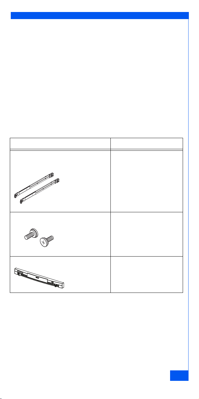
• Information on hardware that you need to provide
• Where to find step-by-step installation and configuration
documentation
• Complete list of SCA documentation
• List of basic installation tasks
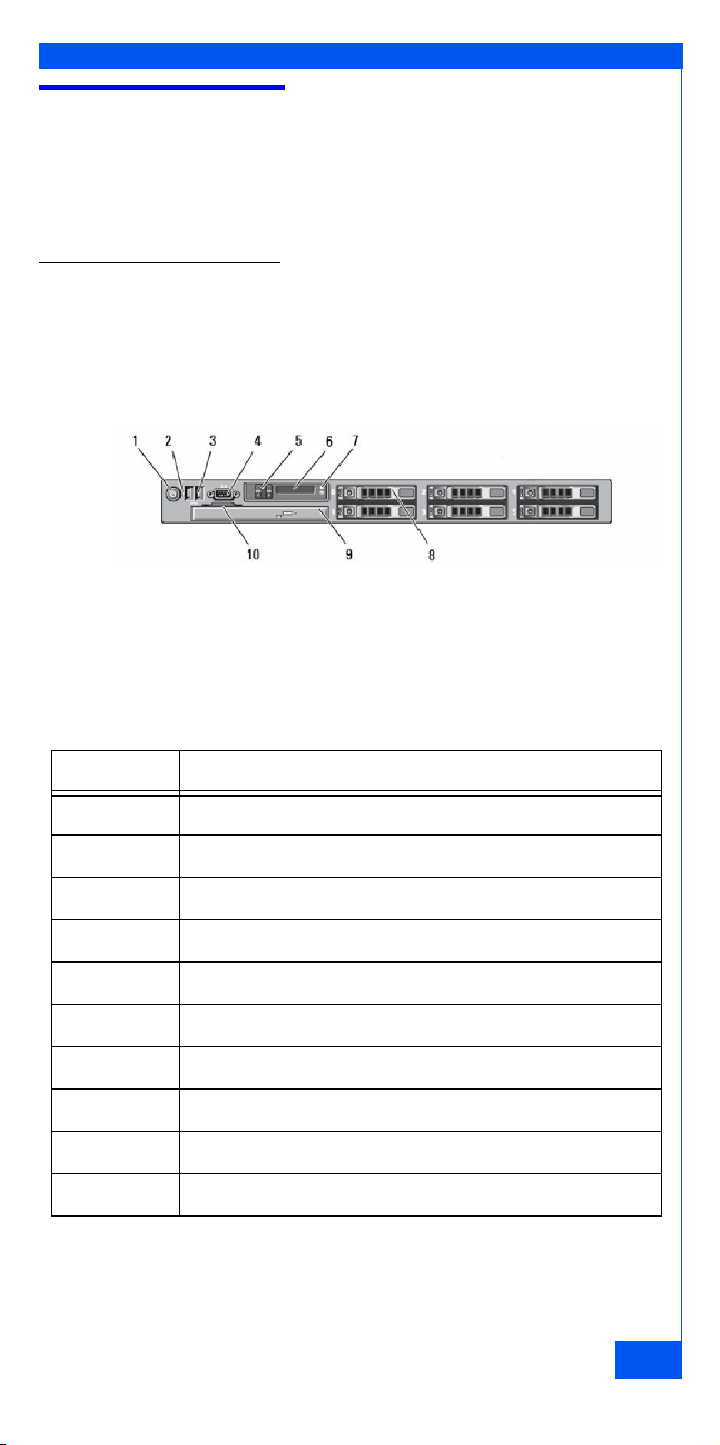
System information and requirements
To initiate compliance analysis, the EMC Ionix Storage Configuration
Advisor Console (GUI) requires the following:
• Microsoft Internet Explorer 6.0 browser with network access to the
appliance or Mozilla Firefox 2 or later that has network access to
the appliance.
• Java 1.6.0_14 or above plug-in for browser.
For support information including supported arrays, fabrics,
providers, host and array discovery, refer to the EMC Ionix Storage
Configuration Advisor Support Matrix.
Important: All SCA documentation is available on the EMC Powerlink®website
(http://Powerlink.EMC.com). Make sure you have a Powerlink account and can
access the site, then download the required documentation before you begin
SCA installation.
In addition, you can access the following documents from the SCA
online help:
• EMC Ionix Storage Configuration Advisor 2.0 Administration Guide
• EMC Ionix Storage Configuration Advisor 2.0 Product Security
Defaults

44
Installation documentation
You need the EMC Ionix Storage Configuration Advisor Installation Guide
for complete information on how to install SCA.
SCA documentation list
Complete SCA documentation list is as follows:
• EMC Ionix Storage Configuration Advisor 2.0 Administration Guide
• EMC Ionix Storage Configuration Advisor 2.0 Support Matrix
• EMC Ionix Storage Configuration Advisor 2.0 Online Help
• EMC Ionix Storage Configuration Advisor 2.0 Release Notes
• EMC Ionix Storage Configuration Advisor 2.0 Performance and
Scalability Guidelines
• EMC Ionix Storage Configuration Advisor 2.0 Installation Quick
Reference
• EMC Ionix Storage Configuration Advisor 2.0 Installation Guide
• EMC Ionix Storage Configuration Advisor 2.0 Non-EMC Software
• EMC Ionix Storage Configuration Advisor 2.0 Hardware Replacement
Guide
• EMC Ionix Storage Configuration Advisor 2.0 Product Security
Defaults

5
Installation overview
The following tasks are required to install the hardware appliance onto
your network, and to begin using the software. Detailed steps appear
in the EMC Ionix Storage Configuration Advisor 2.0 Installation Guide.
Task 1: Assemble the appliance hardware
This section describes how to install the SCA 1U server into the
cabinet.
Figure 1 on page 5 displays the front view of the Dell R610 appliance.
Figure 1 Appliance front view
Table 1 on page 5 describes the components seen on the front view of
the Dell R610 appliance.
Table 1 Dell appliance components (front view)
Item Indicator, Button, or Connector
1 Power-on indicator, power button
2 NMI button
3 USB connectors (2)
4 Video connector
5 LCD menu buttons
6 LCD panel
7 System identification button
8 Hard drive bays (6) - Four 2.5-inch hard drives provided
9 Optical drive
10 System identification panel

66
Figure 2 on page 6displays the rear view of the Dell R610
appliance.
Figure 2 Appliance rear view
Table 2 on page 6 describes the components seen on the rear view
of the Dell R610 appliance.
Table 2 Dell appliance components (rear view)
Item Indicator, Button, or Connector
1 DRAC6 Enterprise
2 VFlash media slot
3 Serial connector
4 PCIe slot 1 (full-height, half-length)
5 Video connector
6 USB connectors (2)
7 PCIe slot 2 (full-height, half-length)
8 Ethernet connectors: embedded 10/100/1000 NIC (4)
connectors labeled Gb1, Gb2, Gb3, Gb4 from left to right
9 System status Connector to cable management arm
10 System status indicator - Provides a power on indicator for the
back of the system
11 System identification - Turns the system ID modes on and off
12 Power supply 1 (PS1) 502-W power supply
13 Power supply 2 (PS2) 502-W power supply

7
Install the appliance in a rack or cabinet
Take the appliance out of the box and mount it into the rack as follows:
1. “Mounting kit parts” on page 7
2. “Removing inner rails from the universal rail kits” on page 7
3. “Attaching the inner rails” on page 8
4. “Installing the universal rails in the cabinet” on page 8
5. “Installing the appliance in the cabinet” on page 9
6. “Installing Bezels” on page 10
Mounting kit parts
The appliance mounting kit includes rails, hardware, and bezel as
listed in the table below.
You will need a # 2 Phillips-head screwdriver to complete the
installation of the rails and appliance(s)
Removing inner rails from the universal rail kits
Figure 3 on page 8shows how to remove the inner rail from each rail
assembly.
1. Pull the blue inner rail release button, and extend the inner rail to
the lock position.
Table 3 Enclosure mounting kit materials
Component Use
2 adjustable universal slide rails. Includes
inner rails for connection to appliance.
Attach front to back on either
side between NEMA channels
2 Phillips M5 18mm screws Stabilize the rail mounting
1U bezel (front rack panel) 1 per appliance- application
specific

88
2. Slide the white disconnect tab forward to release the inner rail
from rest of the assembly, and then remove the rail.
Figure 3 Removing the inner rails from the rail assembly
Attaching the inner rails
Figure 4 on page 8shows how to attach inner rails to each side of the
appliance.
1. Align the protruding rail notches with the connection studs on the
appliance.
2. Push the rail along the appliance until the studs fit securely into
the notches; an audible click indicates that the rail is secure.
Figure 4 Attaching inner rails
Installing the universal rails in the cabinet
Figure 5 on page 9describes how to mount each rail in the cabinet.
1. Pull the middle rail out and into the locked position. Use the
exposed middle rail for leverage as you attach the assembly.
2. From the front of the cabinet, position the alignment pins and
release bracket over the rear cabinet mounting channel. Insert the
alignment pins on the rail assembly into the rear channel holes for
the selected 1U (1.75”) of cabinet space. Push the assembly
backwards onto the channel; an audible click indicates that the
connection is secure.
3. Pull the front alignment pins into position securely in the cabinet’s
front channel. An audible click indicates that the rail is firmly
attached to the channel.
CL4346
Click!
CL4347

9
Figure 5 Installing universal rails
Installing the appliance in the cabinet
WARNING ! The enclosure is heavy and should be installed into a rack by two
people. To avoid personal injury and/or damage to the equipment, do not
attempt to lift and install the enclosure into a rack without a mechanical lift and/
or help from another person.
Before mounting the appliance to the rails, ensure that the ball bearing retainer
sheath is locked forward.
Figure 6 on page 9, Figure 7 on page 10 and Figure 8 on page 10
show how to install the appliance in the rackmount cabinet:
1. From the front of the cabinet, align the inner rails attached to the
appliance with the mounting channels on the slide rails.
2. Slide the appliance halfway into the slide rails.
Figure 6 Inserting the appliance in the cabinet
1
2
Click!
Click!
CL4348
CL4349

10 10
3. Slide the blue release tab and then push the appliance into the
cabinet. An audible click indicates that the slide rails are engaged
and locked.
Figure 7 Securing the appliance in the cabinet
4. To further secure the rail assembly in the cabinet, insert and
tighten a stabilizer screw directly behind each bezel latch.
Figure 8 Installing the stabilizer screws
Installing Bezels
Figure 9 on page 11shows how to install a front bezel.
1. Press the bezel onto the latch brackets until it snaps into place.
2. Lock the bezel with the provided key; put the key in a secure
place.
1
2
3
Click!
CL4350

11
Figure 9 Installing the bezel
3. Wire the appliance:
a. Plug the LAN cable into the Gb1 connector.
b. Plug a monitor into the Video port and a keyboard and mouse
into USB ports, or alternatively use a KVM connection.
c. Plug the two power supplies (items 12 and 13 in Figure 2 on
page 6) into different power zones, to support fault tolerance.
d. If the appliance does not turn on automatically, press the black
power control button on the front-left of the appliance.
CL4408

12 12
Task 2: Run installation script
After hardware installation, you must configure the appliance for your
site, and then run the installation script as described in the EMC Ionix
Storage Configuration Advisor Installation Guide.
Have the following site information handy:
• IP address
• Gateway
• Hostname
•DNS
•Netmask
• Broadcast—The broadcast address for a specific network includes
all values in the host portion of the IP address. On class C
networks, the host portion is the last byte (for example, the fourth
segment), and on class B networks it is the final two bytes. Thus,
the broadcast address for the class C network 192.168.3.0 would be
192.168.3.255.
•SecondaryDNS
• Network—Set to your class C, for example, 192.168.10.0.
• Time zone—Use the Linux standard time zone for your site. Refer
to the EMC Ionix Storage Configuration Advisor Administration Guide
for a complete list.
Task 3: Administer SCA software
SCA is provided with a Security Administrator (admin user with
highest Security Administrator privileges) for initial login. This user
can add and modify users, as well as perform normal administrative
tasks. For complete information refer to the EMC Ionix Storage
Configuration Advisor Administration Guide.
Technical support
If you have questions or issues while installing the EMC Ionix Storage
Configuration Advisor appliance, call your EMC Customer Support
Representative or refer to the EMC Powerlink website at http://
Powerlink.EMC.com.
Table of contents