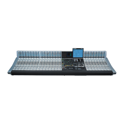
HARRIS INTERTYPE GATES STEREO 80 User manual

www.SteamPoweredRadio.Com
WARRA
NTY
Seller warrants new equipment manufactured by
Gates
Radio Company against defects in material or work1
ma
nsh
ip
at
the
time
for
delivery thereof, that develop under normal
use
within
a period
of
one year (6 month
s_
on moving.parts) from the date
of
shipment,
of
which Purchaser gives
Sel
ler prompt written notice.
Other.
manufacturers' equipment,
if
any, including electron tubes, and towers
shall
ca
r
ry
only
such
manufacturers4
standard warranty.
Seller's
sole
responsbili
ty
fo
r any breach
of
the foregoing provision
of
this
cont
ract,
with
resp
ect
to
any,
equipment
or
parts
not
conforming
to
the warranty
or
the description herein contained, isat its option,
(a)
to
repair
or
replace
such
equipment
or
parts _upon the return thereof f.o.b. Seller's facto
ry
within
the period.
aforesaid,
or
(b)
to
accept the return thereof f.'o.b. Purchaser's
point
of
installation, whereupon Seller
shall
either (1)
issue
a credit
to
Purchaser's account hereunder in
an
amount
equa)
to
an
equ
itable
po
r
tion
of
the
total contract price,
without
·interest,
or
'(2)
if
the total contract price
has
been
paid, refund
to
Purchaser
an
equitable
port
ion thereof,
without
interest.
If
the Equipment
is
described
as
used,
it
is
sold
as
is
and
where
is.
If
the contract _covers equipment
no~
owned by Seller
at
th
isdate
it
is
sold subject
to
Seller's acquisition
of
possession
and title.
Sel
ler
assumes
no responsibili
ty
for design characteristi
cs
of
sp
ec
ial equipment manutactured
to
specifications
supplied by
or
on behalf
of
Purchaser.
Se
ll
er shall not be liable
for
any expense whether
for
repairs, replacements, material, service
or
otherwise,
incur
red
by
Pyrchaser or modifications
made
by
Purchaser
to
the Equipment
without
prior
written
consen
t
of
Seller.
EXCEPT AS SET FORTH HEREIN,
AND
EXCEPT
AS
TO
TITLE,
THERE ARE NO WARRANTIES,
OR
ANY
AFF
IRMATIONS OF FACT
OR
PROMISES BY SELLER, WITH REFERENCE TO THE EQUIPMENT,
OR
TO
MERCHANTABILI
TY,
INFRINGEMENT,
OR
OTHERWISE, WHICH EXTEND BEYOND THE DE-
SCRIPTI
ON
OF THE EQUIPMENT
ON
TH
E FACE HEREOF.
RETURNS
AND
EXCHANGES
Do
not
return any merchandise
without
our written approval and Return Authorization.
We
will provid~1
specia
l shipping instructions and a code number that
will
assu
re proper handling
and
prompt
issuance
of
credit.
Please
furnish complete details
as
to
circumstances
and
reasons
when requesting return
of
mer-
I
chandi
se.
Custom
built
equipment
or
merchandise specially ordered
for
you
is
not
returnable.
Where
return
is
at
the request of,
or
fo
r the convenience
of
the customer, a restocking fee
of
15%
will
be
cha
rg
ed
.
All
returned merchandise must
be
sent freight prepaid
and
properly insured
by
the customer.
When
writing to;,
Gates
Radio Company about
your
order,
it
will
be
helpful
if
you specify the Gates
Fa
cto
ry
Order Number
or
Invoice Number. .
I
WARRANTY
ADJUSTMENTS
In
the event
of
equipment failure during the warranty
pe
riod, replacement or repair parts may be provided1
in accordance
with
the provisions of the Gates Warranty. In most
cases
you will
be
required
to
return the.
defective merchandise
or
part
to
Gates f.o.b. Quincy, Illinois
for
replacement or
re
pair. Cost
of
repair
parts
or
replacement merchandise
will
be
billed
to
you
r account
at
the time
of
shipment
and
compensatingJ
credit
will
be
issued
to offset the charge when the defective items
are
returned.
't
. i
MODIFICATIONS
Gates
reserves
the right to
modify
the design
and
specifications
of
the equipment shown in this catalog:
without
notice
or
to
wi
thdraw any item
from
sale
provided, however, that any modifications shall
not
ad
-'
verse
ly affect the performan
ce
of
the equipment
so
modified.
"
r.
r
'
I"
;

www.SteamPoweredRadio.Com
('J
LO
TECHNICAL
MANUAL
STEREO
80
CONSOLE
994 6867
001
INTRODUCTION
The Stereo 80
is
a high
quality
stereophonic console which provides all
necessary studio functions and facilities
for
the typical
FM
station
that
broadcasts stereophonic programs exclusively.
This Technical Manual provides the
necessary
informat
ion
fo
r application,
installation, operation, and maintenance
of
the Gates Model 994 6867
00
1
Stereo 80 Console.
888 1152 001
Price:
$
10
.
1>0
iii

www.SteamPoweredRadio.Com
SECTION
1.0
1.1
1.
2
2
.0
2. 1
2. 2
2.3
2.
4
2. 5
2. 6
2. 7
2.8
2. 9
2
.10
2.
11
2.12
3. 0
3. 1
3, 2
4 . 0
<"I
4.1
u"\ 4. 2
~
~
4.3
4.4
5. 0
STEREO
80
CONSOLE
994 6867 001
TABLE
OF
CONTENTS
FRONT
I
SPIECE
INTERIOR
VIEW
INTRODUCTORY
PAGE
..
.
..
.............
......
GENERAL
DESCRIPTION
AND
SPECIFICATIONS
General
Information
Specifications
...........
..
....
..
...
...........
...
..
..................................
INSTALLATION
PROCEDURE
..
.....
.......................
..
.....
Unpacking
Instructions
Installation
•••••••
• ..............
..
.
..
..............
..............................
Power
Connections
·
··
· • ·
··•··•••·••·
• · ·
····
Fig
. 2,
2A
, Power
Transformer
Primary
Connections
Input
Connections
. . . .
....
.
....
.
.•..•.
.
•.•......
•
..
•
...
.
Fig
.
3,
3A
,
Terminal
Boards
,
Input/Output
Microphone
Inputs
Medium
Level
Inputs
Network/Remote
Input
.................
..
...........
External
Monitor
Input
.
••...
...
..
. .
..
..
.
..•.....
..
.
....
Output
Connections
··
··
·•·
····
····
····•·
•••
•
••··
••·
·
Fig.
4,
TBS,
TB6, TB7,
Monitor
Speakers,
Warning
Lights
Muting
.•.
. . .
.......
..
.
...............
.....
. .
...
.
.•.
•.•.
Fig.
5,
TB15
Muting
Connections
Station
Grounding
Accessory
..•.•.
• •
••••
OPERATION
.
..
........
...
..
...
.............................
PAGE
i
ii
iii
1-1
1-1
1-1
2-1
2
-1
2
-1
2-1
2- 2
2-2
2-2
2-2
2- 3
2- 3
2
-4
2-4
2-4
3-1
Control
Adjustments
.•
•.
•••••••••••••••
••
•••
••••••••••••
3-1
Talk-Back
(To Remote
Location
Prior
to
"
On
Air"
Broadcast)3-2
MAINTENANCE
..
•
••••.
••••
•
.••
.••••••••.•.
•
•••
30/50
ohm
Microphone
Modification
••••
••••
•
Troubleshooting
••.
• •
•••••
•
•••
Bias
Adjustment
••••
,
••••.
Troubleshooting
Guide
Fig
.
6,
Loss
Pad
Chart
...........
..
..
......
ELECTR
IC
AL
PARTS
LIST
...
..
...
....................
...
.
..
4-1
4-1
4-1
4- 1
4- 2
5
-1
/5
-9
iv

www.SteamPoweredRadio.Com
SECTION
PAGE
6. 0
DRAWINGS
Gates
Dw
g.
No
. 815 4265
001,
Relay
and
Muting
Driver
Board
815 4821
001,
Muting
Assignment
815 4822
001,
Inter-Connecting
Cable
815 4830
001,
Console
Installation
Layout
827 7491
001,
A
udio
Output
Card
827 9272
001,
Pr
e
-Ampli
fier
827 9310
001,
Au
dio
Booster
828 0021
001,
Installation
Dwg
.,
External
Connections
842 6555
001,
Block
Diagram,
St
ereo
80
842 7179
001,
Power
Supply
Panel
852 6795
001,
Ov
e
rall
Schematic,
Stereo
80
V
•

www.SteamPoweredRadio.Com
N
lD
GATES STEREO
80
CONSOLE
1.0 GENERAL DESCRIPTION
AND
SPECIFICATIONS
1.
1 The Stereo 80 console provides the
typi
cal
FM
radio station
with
al
I the
necessary
facilit
i
es
required
to
program stereophonic programs exclusively.
1.
2
Th
is
console makes
use
of
plug-in, printed
circuit
modules for
flexibility
and
ease
of
service.
Channels 1 and 2 are equipped
with
low noise preamplifiers, and are to
be
used
with
low impedance, broadcast-type microphones.
Each
of
these channels may
select
from
two
different
input
signals
by
means
of
a
front
panel switch.
Channel 3
is
equipped
with
low
noise preamplifiers and
also
intended
to
be
used
with
low
impedance, broadcast-type microphones. This channel
has
a
single
input
and
is
assigned
to
the control room since these microphones
functions
as
part
of
the talk-back system. Channels 4,
5,
6,
and 7 are
al
I
medium level inputs and may
be
used
with
turntable preamplifiers, reel-to-reel
tape,
or
cartridge machines.
All
channels have
input
transformers
with
center
taps. They are supplied
with
the center taps ungrounded. A nominal level
of
-20
dBm,
or
+4
dBm at 600 ohms
is
required.· In
put
pads
for
the
+4
dBm are
provided
on
the various tape inputs.
Channel 8 is specifically designed to function
with
network
and remote lines
as
sources. Various combinations
of
preview, ta
lk
back and program cue
are
possible using the
front
panel
sw
it
ches
. A nominal
input
of
-20
dBm at 600
ohms is required.
Each
channel may be switched
to
either the PROGRAM
or
AUDITION
positions
to
permit independent monitoring
or
recording
of
any
of
the
incoming sources
without
disturbing programming. Channels 4 through 8 have
cue positions associated
with
the channel attenuators which provide signal
to
the amplif
ied
cue system. This signal
can
be
monitored
by
an
int
ernal speaker
or
external headphones. On channels 1 and 2. the center position
of
the
PROGRAM-AUDIT
ION key switch provides a microphone cue signal
to
the
cue
selector switch. On channel
3,
this position is
used
with
the
control
room
microphone
for
talkback.
A protective system
of
warni
ng
lights and relay muting is provided
to
prevent
acoustic feedback and broadcasting
of
cue signals when
"I
ive'' microphones
are in
use.
SPECIFICATIONS
MICROPHONE (Channels
1,
2.
and 3
to
Program Line Out)
Maximum Gain:
Frequency
Response
:
Distortion:
Noise:
100,
±2
dB
±1
dB, 20
to
20,000 Hz
Less
than 0.5%, 20
to
20,000 Hz at
+24
dBm
output
More than 75 dB below +18 dBm
output
with
-50
dBm input.
Equivalent
input
noise
is
better than
-125
dBm, 20
to
20,000 Hz
.,.
a
1-1

www.SteamPoweredRadio.Com
1--
2
Crosstalk:
Microphone Impedance:
Less
than 10 dB above the noise,
with
normal levels and control settings
at
15 kHz
150ohms, balanced
with
C.
T.
37.5 ohms, balanced, no C.T.
MEDIUM
LEVEL
(Channel
s4-7
to
Program Line
Out)
Maximum Gain:
Frequency
Response
:
Distortion:
Noise:
Crosstalk:
Input
Impedance:
60,
±2
dB/36,.±2 dB
±1
dB, 20
to
20,000 Hz
Less
than 0.
5%,
20
to
20,000 Hz at
+24 dBm
output
More than 80 dB below +18 dBm
output
with
- 10 dBm input,
20
to
20,000
Hz
Less
than
10
dB above the noise,
normal levels and control settings at
15 kHz
600ohms, balan
ce
NETWORK/REMOTES (Channel 8)
to
Program Line
Out
Maximum Gain:
Frequency Response:
Distortion:
Noise:
Crosstalk:
I
nput
Impedance:
MONITOR CIRCUITS
Maximum Gain:
Frequency Response:
Distortion:
54,
±2
dB/60,
±2
dB
± 1 dB, 20
to
20,000 Hz
Less
than 0.5%,
20
to
20,000 Hz at
+24 dBm
output
More than 80 dB below
+18
dBm
output
with
-10
dBm input,
20
to
20,000 Hz
Less
than 10 dB above
th
e noise,
with
normal levels and control settings at
15 kHz
600 ohms, balanced
Mi
c-
Pgm
-Mon
Out
131,
±2
dB
Mi
c-
Aud
-Mon
Out
131,
±2
dB
Med-Pgm-Mon
Out
90,
±2
dB
Med-Aud-Mon
Out
90,
±2
dB
Ext
-Mon-Mod
Out
59,
±2
dB
± 1 dB, 30
to
15,000
Hz
L
ess
than
1%,
30
to
15,000 Hz
at +40 dBm (10 Watts)
output
into
8 ohm load
-
Cl
"-

www.SteamPoweredRadio.Com
N
LO
Noise:
Crosstalk:
PHYSICAL SIZE
Console:
Console
We
i
ght:
POWER
SUPPLY
(Panel
Assembly)
Inp
ut
Power Requirements:
More than 80 dB below +40 dBm
(10 Watts)
output
, 30
to
15,000
Hz
L
ess
than 10 dB above the noise,
with
normal levels and control
settings at
15
kHz
45
inches wide
15.5 inches deep
7.75 inches high
105 lbs.
(11
4.3 cm)
( 39.37 cm)
( 19.68 cm)
( 47.63 kg)
Li
ne
Vo
l
tage
and Frequency: 117 V (As supplied)/234 V, 50/60 Hz
Power Consumption:
Output
Voltage:
Physical Size:
Weight:
120 Watts, maximum
Four (4) outputs,
45
V
DC
at 2.
25
Amps.
eac
h, one (1)
output,
unregulated, 65 V
DC
7.0 in
ches
hi
gh
19
.0 inches
wide
7.75 inches deep
21
lbs. (9.53 kg)
(17.
78cm)
(48.26 cm)
(19.
68cm)
1-3

www.SteamPoweredRadio.Com
N
LI)
,-1
,-1
2.0
2.1
INSTALLATION
PROCEDURE
UNPACKING INSTRUCTIONS
Carefully unpack
the
console and inspect
it
for
shipping damage.
All
parts
should be securely fastened
to
the cabinet
or
sub-chassis; any loose parts should
be inspected
for
frayed
or
broken wires.
If
any damage
is
foun
d, contact the
carrier immediately.
The
fo
llowing main items
will
be enclosed:
1) Stereo
80
Console
2) Knob Decal
Kit
3) Technical Manual
4}
Cue
and Program Phone Jacks,
Oty
of
3
5) Power Supply
Panel
Assembly
2.2
INSTALLATION
As supplied
from
the
factory,
the
Stereo
80
has
seven
"bumper"
feet
for
desk
top
mounting. These bumpers
space
the
bottom
of
the console away
from
the
desk surface to provide proper ventil
at
ion.
If
permanent, desk-top mounting
is
required, remove the hardware
from
the
"bumper"
feet and replace
same
with
longer bolts
or
screws,
but
remount the bumpers in their original positions
to
allow
the
necessary
air
circulation beneath
the
console.
All
cable connections
are made through the
bot
tom
of
the
console.
2.3
P.OWER
CONNECTIONS
The separate power supply panel
is
normally
mounted beneath the desk
or
table
or
in a rack close
by
and should be
sepa
rated several feet
from
the
console
in
a position which permits free
air
circulation around
it
. As shipped
for
domestic
use,
the power supply panel's transformer
pr
imary windings are
parallei-connected
for
117 V AC,
50/60
Hz operation. However, the
four
primary
windings are accessible
by
removing the power supply panel
front
cover and then
the
P.C.
board, and may be reconnected in series
for
234
YAC,
50/60
Hz
operation,
if
desired. These connections are illustrated in the Trans-
former Diagram, Fig. 2. Connect the power supply panel to the main console
by
interconnecting 2TB1
of
the power supply panel
to
TB10
in
the
main
console. The
two
terminal boards are connected
like
terminal numbers to
like terminal number.
That
is,
2TB1-1 to
TBl0-1
or
TBl0-7
to
2TB1-7.
See
interconnecting drawing, 815
48
22
00
1
of
this book.
Cable length should
not
exceed 100 feet and twisted shielded wire should be
used. A number
of
single twisted pairs (below
No
. 8451
or
si
mi
lar) may be
used
or
a single cable
with
many internal twisted pairs (Beldon
No
.
8766
or
similar) may be used. In either
case,
the interconnecting cable should
be
paired
in
the
following
manner:
WI
RE
NO. POWER SUPPLY T
ERMINAL
NO.
2TB1-
1 1 & 2
2
3&4
3 5 & 6
4
7&8
5 9 &
10
CONSOLE T
ERMINAL
NO.
TBl0-
1 & 2
3&4
5&6
7&8
9 & 10
2
-1

www.SteamPoweredRadio.Com
2.4
2.5
J
6
11
& 12 11 &
12
7 13 & 14 13 &
14
8
15
& 16 15 & 16
9 17 & 18 17 & 18
10 19 & 20 19 & 20
11
21 & 22 21 & 22
INPUT CONNECTIONS
The
input
cables should
be
soldered
to
t
he
terminals
of
TB
1 and
TB2
which
are locat
ed
along the
front
surface
of
the module compartments. These cables
should
be
2-con
ductor
shielded wire,
with
an
overall
viny
l jacket. The vinyl
jacket pr
eve
nts the shield
from
shorti
ng
to
other building groun
ds,
thus elimi-
na
ting possible ground loops.
See
the Installation and Schematic/Wiring
diagrams
fo
r input and ou
tput
connections. Solder the
input
shields to the
ground
bus
provided below
TB
1 and TB2. Connect
left
inputs
to
T
B1
and
right inputs
to
TB2.
CAUTION: To
prevent
unwanted
ground
loops,
all
wiring
c
on
-
nected
to
TB1 and
TB2
should be free
from
ground
connections
in
the source
equipment
(microphones, turntable, preamplifiers, tape re-
corders, etc.).
An
ohmmeter
check is recommend-
ed
to
be certain each
wire
is
not
grounded before
connect
ing
it
to
the console
input.
If
this check
is made, those sources showing
no
grounds
may
exhibit
lower
noise
if
the
input
transformercenter
tap
is
grounded. The center taps should never be
gr
ounded
if
the source line hasa
ground
.
--
MICROPHONE INPUTS
Mic
A,
Ch
1 and Mic
A,
Ch 2 inputs are
assigned
(See
Muting Assignments,
Dwg. No.
815
482
1 001)
as
Studio A microphone inputs.
Mic
B,
Ch
1
and
Mic B,
Ch
2 inputs are
?ssigned
as
Studio B microphone inputs. The inputs
for
Ch 3 are
for
the control room microphones.
The nomin
al
l
evel
to
these inputs is - 60 dBm at 150 ohms. Microphones
with
impedan
ces
from
100
to
250 ohms may
be
used.
To
use
30/50
ohm microphones,
see
the modification instruction under
Section 4.0,
MA
INTENANCE.
2.6 MEDIUM
LE
VEL
INPUTS
All medium level
input
channels, 4 through 7, are 600 ohm, balanced.
Nominal in
put
levels are -
20
dBm
fo
r the turntable inputs and
+4
dBm for all
tape inputs. The i
nput
levels
fo
r the
va
rious tape inputs
ca
n
be
lowered
to
-2
0
dBm
by
removing the correct
pad
on
TB
1 and
TB2
.
See
main Schematic
for
resistor numbers. If specific i
nput
sources are free
of
groun
ds,
the center taps
of
the co
rr
espo
ndi
ng
in
put
transformers may
be
grounded
for
lowest
no
i
se
.
2.7 NETWORK/REMOTE INPUT
2-2
The N
etwo
r
k/
Remote inputs on Channel 8 are 600 ohm,
ba
lanced. The
nominal
in
p
ut
level is
-20
dBm.

www.SteamPoweredRadio.Com
.....
0
0
11"1
"
1.0
11"1
11"1
.....
GO
N
11"'1
,-1
.....
2TB2
#4
72
073
4
000
BLK
PRIMARY
f
J
117
V
AC
l____i
BLK
/
GRN
BL
K/
REO
23
4V
AC
J
117
VAC(AS SH
IPP
ED
)
F
IG
. 2
2TB2
4
PRIMARY
BLK
BLK
GRN
BL
K/
REO
234
V
AC
(
OPTIONAL
)
FIG
.
2A
SEC
ONDARY
[
[
[ J =
JU
MPER
[
SEC
ONDARY
[
[
[ J =
JUMPER
[
POWER
TRANSFORMER
PRiliARY
CONNECTIONS
STEREO
80
CONSOLE

www.SteamPoweredRadio.Com
N
LD
2.8 EXTERNAL MONITOR INPUT
Each
external
Monitor
Input
presents a balanced bridging
input
to
a 600 ohm
source. The nominal
input
level is
-20
dBm. This value may
be
raised
or
lowered
by
adjusting the
va
l
ues
of
R32 and R34 on
TB
1 and R73 and R75 on
TB2
.
(See
main Schematic Dwg. No. 852
6795
001
.)
2.9 OUTPUT CONNECTIONS
Th
e
left
and right program li
ne
outputs
are 600 ohm, balanced, and provide
+8
dBm
output
level when the
VU
meters r
ead
"O"
VU.
These outputs appear
at
terminals 69 and
71
of
TB1 and terminals 69 and
71
of
TB2. The maximum
output
level obtainable at
these
points
is
in
excess
of
+30 dBm
into
600 ohms.
This
output
level capability provides headroom
to
prevent clipping
of
the
program signal peaks when operated
at
normal (+8 dBm) level. A high
impedance headphone
output
is
available at terminals 75 and 76
of
TB1 and
TB2. These outputs are bridged
across
the program
output
line before the
6 dB line pad.
The cue headphone jack connection points are terminals 82, 84, and 86, and
are intended
for
a switch-type phone jack.
If
this type jack
is
not
used,
a
jumper must
be
used
across terminals 82 and 84. Using this jumper, however,
w
il
l
not
allow the inserted headphones to disable the internal cue speaker,
which may
be
desirabl
e.
The cue headphone terminals are on TB2.
The connections for the
monitor
speakers
are
located on
TB5
(Left) and
TB6
(Right), underneath the swing-up transformer deck which
is
located between
the two card guide assemblies. Loosen
in
g the
two
thumb screws at the rear
of
the deck
will
allow
it
to
swing
up
toward the
front
panel, exposing
TB5
and
TB6. Terminals 1 and 2 are
for
the lobby speakers which
are
not
muted.
Terminals 3 and 4 are
for
the Studio A speakers, terminals 5
and
6 are
for
the
Studio B speakers, and terminals 7 and 8 are for the control room speakers.
These· three locations are all muted. For these speakers, No. 22,
or
larger,
twisted pair unshielded wire is recommended.
It
is
important
to
make certain
that
the total load on
each
monitor
amplifier,
from
all speakers connected
to
it,
does
not
fall below 8 ohms.
If
it
does,
the
automatic protection system
wil
l operate and the
output
from
the speakers
may sound distorted,
or
garbled.
If
several
8 ohm speakers are needed,
use
matching transformers listed under
ACCESSORIES. If
only
two speakers are required, two
16
ohm units con-
nected in paraIlei,
or
two
4 ohm speakers connected in series, to form the 8
ohm load,
would
be
acceptable. These connections should
be
made
with
unshielded wire pairs,
size
No. 22, or larger.
Any
combination
of
speakers
is
satisfactory
as
long
as
the resultant load impedance
is
8 ohms
or
higher.
The connections
tor
the warning lights are on
TB7,
located underneath the
swing-up transformer deck. Terminals 1 and 2 on
TB7
are
for
the 117 V AC
used
to energi
ze
the warning lights.
If
possible, connect the neutral side
of
the
line
to
terminal 2 and the
hot
side
to
terminal
1.
Terminals 7 and 8, on TB7,
are
for
Studio A, terminals 5 and 6 are
for
Studio
Band
terminals 3 and 4 are
for
the Control room. The warning lights should
not
be
grounded except
through the power Iine. The current drawn
by
the warning lights should
not
exceed 2 amperes.
2-3

www.SteamPoweredRadio.Com
2.10
MUTING
As supplied
from
the
factory,
the
Stereo
80
is arranged
to
mute
in
the
follow-
ing manner:
Mic
A,
Ch 1 and
Mic
A,
Ch
2
will
mute
the
Studio
A speakers.
Mic
B,
Ch
1 and
Mic
B, Ch 2
will
mute
the
Studio
B speakers. The microphone
on Ch 3
is
intended
for
the
Control
room and
will
mute
the
Control
room
speakers and
the
internal cue speaker in
the
console. The assignment
is
arbitrary
for
Channels 1 and 2. Channel 3 is
fixed
and must remain
as
assigned.
It
is,
however,
easy
to
re-assign Channels 1 and 2
if
the operation
of
the
muting
system is understood.
It
operates
as
follows: A
contro
l signal
is
derived
from
terminal 1
of
the
Relay and
Muting
Driver board. This signal is fed
to
each
of
the
PROGRAM-AUDIT
ION switches associated
with
a microphone (Channels
1,
2,
and 3).
In
the
case
of
Channel 3,
if
the key switch
is
placed in either
the
PROGRAM
or
AUDITION
mode, this signal
is
then fed back
to
terminal
11
of
the Relay and
Muting
Driver boards and mutes t~e
Control
room speakers.
(See
Muting
Assignment, Dwg. No.
815
482
1 001.) In
the
case
of
Channels 1
and 2,
if
the
PROGRAM-AUDITION
key
is
thrown,
the drive signal is then
fed
to
the
wiper
of
the
appropriate MIC
A/MIC
B selector switch. Depending
upon what position the selector switch
is
in,
the
drive signal is then fed
to
terminals 1,
2,
5,
or
6
of
TB15
located between switches
S1
and
S2
on the
rear
of
the
front
panel. Terminal 3
of
TB
15
is
the
receive
point
for
the Studio
A
muting
drive signal, and terminal 4 is the Studio B receive
point.
With this
information,
it
is
possible
to
set
up
any
muting
configuration
by
adding
or
changing several jumpers
on
TB
15.
FOR
EXAMPLE
:
MIC
A/Ch
1,
MIC
A/Ch
2
to
mute
Studio
A (As supplied):
Jump 1
to
3, and 5
to
3,
on
TB
15
MIC
A/Ch
1,
MIC
A/Ch
2
to
mute
Studio
B:
Jump
1
to
4, and 5
to
4, on
TB15
All
Ml
C's
to
mute
.
Studio
A :
Jump 1
to
3, 2
to
3,
5
to
3, and 6
to
3,
on
TB
15
2
.1
1
STATION
GROUNDING
The ground stud, located underneath the trar.s
former
deck
at
the center rear,
should be connected
to
the
station ground
by
means
of
a heavy copper wire
or
strap.
THIS
SHOULD
BE
THE
ONLY
GROUND
CONNECTION
TO
THE
STEREO
80
CONSOLE.
2.12 ACCESSORY
2,.4
A
48/8
ohm
Speaker Matching Transformer, Gates Part No.
478
0291
000
can be supplied
on
order,
for
use
in studio
monitoring
wiring
requirements.
-
CJ
"-

www.SteamPoweredRadio.Com
N
Lr>
3.0 OPERATION
3.1 CONTROL ADJUSTMENTS
All
gain adjustments should
be
made
with
the left and right master gain
Controls
set
as
calibrated at the factory.
In
this position, the master gain
Controls insert
16
dB
of
attenuation. This setting provides a good balance
in the
monitor
circuit when switching
from
PROGRAM
to
AUDIT
ION. Also,
it
is the best choice in providing adequate operating margins
of
signal-to-noise
and
"headroom".
Set
the cue and
monitor
gain Controls at mid-range and all chann
el
attenuators
at
"12"
on the dial (about 1
:00
o'clock position).
Apply
power
to
the console
and check
to
see
that the
VU
meters are illuminated.
With a program signal on one
of
the Medium Level inputs
(for
example, TT1).
throw the TT1
input
selector
to
the
Ch
4 position,
an€l
set the key switch for
Channel 4
to
the
"P"
(Program) position. The
VU
meters should respond to
the program level variations. Adjust the program level at the source
of
the
signal (Turntable)
for
peaks
of
100 indicated on the
VU
mete(s.
Set the
monitor
selector switch
to
PGM
and adjust the
monitor
gain Control
for a comfortab
le
level from the control room
monitor
speakers.
Operate the channel 4 key switch
to
the
"A"
(Audition)
position
to
remove
the signal
from
the program channel and connect
it
to
the audition channel.
Moving the
monitor
selector switch
to
AUD
allows monitoring
of
the audition
channel
with
the
same
monitor
speaker level
as
before.
Set the TT1
input
selector to the
Ch
5 position, operate the key switch for
channel 5
to
the
"P"
position, and note
that
the
VU
meters are indicating
program variations which are now controlled
by
the channel 5 attenuator.
Monitor
and audition operation
wil
l
be
the
same
as
channel 4, described above.
Turn
the channel 5 attenuator
to
the CUE position, and adjust the cue gain
Control
for
a comfortable level
from
the cue speaker in the console
or
external
headphones.
Similarly, operate
the
other Medium-Level inputs (TT2, TAPE 1, CT1,
etc
.).
adjusting the program level at the source
of
the signal. This technique allows
al
l cha
nn
el attenuators
to
be
used
in approximately the
same
position
("12"
on the dial)
for
normal
VU
meter indications.
Operate the
Ch
1 microphone
input
selector MIC A and the
Ch
1 key switch
to
"P"
position. Speaking about one
foot
from
the microphone should give a
normal indication on the
VU
meters. The microphone signals may
be
switched
to the audition channels
by
operating
Ch
1 key switch
to
"A"
position, and
monitored
in
a normal manner.
If
the Muting Assignments are correct,
monitaring speakers near the microphones should
be
muted, and the warning
lights in
that
area
should
be
"On".
Similarly, operate channel 2 and channel 3
to
check levels and Muting Assign-
ments. By leaving the channel 1 and 2 key switches in the center, or neutral
position, and selecting MIC 1
or
MIC 2 on the cue selector switch, you should
be
able
to
monitor
these microphones through the cue system.
The center position
of
the channel 3 key switch
is
associated
with
the
talk
back system, and
will
be
described later.
3-
1

www.SteamPoweredRadio.Com
The sources feeding channels 4, 5, 6, and 7 are directed
to
the correct channel
by
using the
input
selector switch on the upper part
of
the
front
pane
l.
When
a
given source selector
is
pressed
downward, the signal
is
directed
into
the
channel
directly
below the switch.
When
in the
"Up"
position,
it
goes
to
a
different
channel.
Each
input
is
clearly labelled above the i
nput
selector
switch.
The
four
input
selectors above the channel 8 attenuator are
for
the network
feed and the remote lines. When
in
the
"Down"
posi
tion,
the inputs
mix
into
channel 8. The center position
of
the
network
switch provides a 600 ohm
termination
for
the feed line, while the center position
of
the three remote
switches provides a program cue
to
the remote location
from
the
monitor
ampl
ifier
in the console. In the
"Up"
position, the inputs
can
be
previewed
through the cue system. The three remote inputs also
use
this position
for
talk back.
NOTE:
The
Network input selector
key
should never
be
in the
"Up" position when the talk back feature is used.
3.2
TALK
-BACK (To remote location,
prior
to
"On
Air"
broadcast)
3-2
Talk-back
to
the remote location
is
accomplished in the following manner:
The correct
input
se
lector switch,
RMT
1.
RMT
2,
or
RMT 3, is pl
aced
in the
"Up"
(Preview-Talk-Back) position. The cue selector switch
is
placed in the
BUS position and the control room, channel 3,
PROGRAM-AUDIT
ION key
switch
is
placed in the center
or
neutral position.
The signal coming
from
the remote location is placed on the cue bus
and
is
heard over the cue speaker
or
headphones. The l
evel
is
control
led
by
the cue
gain control.
When
you
wish
to
talk
to
the remote location, talk
into
the
control room microphone
wh
ile holding down the
white
push-to-talk switch,
located on the
left
side
of
the
top
front
panel.
In
doing this, the
output
of
the
control room microphone preamplifier
is
fed directly
to
the cue
amplif
ier, the
output
of
whi
ch
is
then fed down the remote line. The level going to the
remote position should
be
set
by
using the channel 3 attenuator.
Use
the
push-to-talk switch
only
while talking.
c.:
r-..
Table of contents


