EML Electrocomp 500 User manual

TURN
IT
ON!
Set
the
500
on
a
flat
surface.
Unwrap
the
power
cord
and
plug
it
into
a
110
volt
outlet.
If
your
wall
socket
will
not
accept
this
plug,
use
a
universally
available
3
to
2
adapter.
Do
not
cut
the
third
prong
off
of
the
500
power
cord.
Turn
on
the
power
switch
located
near
the
fuse
holder
on
the
back
of
the
500.
(If
the
fuse
ever
blows,
only
replace
it
with
a
1/4
amp
SLO BLO
fuse.)
The
500
must
be
connected
to
a
sound
system
to
produce
a
sound.
Three
separate
outputs
are
available
for
connecting
the
500
to
different
sound
systems.
1.
Hi
Out.
This
output
is
used
in
connecting
the
500
to
stereo
amplifiers,
tape
recorders,
and
organs.
To
complete
this
connection,
take
the
phono
to
RCA
patch
cord.
Place
the
phono
end
into
the
plug
where
it
says
Hi
Out.
Take
the
RCA
pin
end
and
plug
it
into
your
amplifier
where
it
says
Aux
or
Tape
Mon.
2.
Lo
Out.
This
output
is
used
for
connecting
the
500
to
guitar
type
amplifiers
and
other
electronic
music
amplifiers.
This
connection
is
made
by
taking
a
phono
to
phono
patch
cord.
Plug one end
into
the 500
where
the
Lo
Out
is.
Take
the
other
end and
plug
it
into
the
amplifier.
Scan by Manual Manor
http://www.markglinsky.com/ManualManual.html

3.
Phones.
This
output
is
for
monitoring
with
high
impedance headphones
(500
ohms
or
greater).
When
connecting
the
500
to
an
amplifier
be
sure
that
the
volume
slide
pot
on
the
500
is
all
the
way
down
and
the
volume
control
on
your
amplifier
is
all
the
way
off.
This
is
to
insure
the
safety
of
your
speakers.
The volume
of
the
Hi
and
Lo
Output
jacks
is
controlled
by
the
synthesizer's
output
Volume
slide
control.
The
output Volume
slider
does
not
vary
the
volume
when
monitoring
the
headphones.
This
permits
you
to
monitor
the
500
on
stage
without
having
the
sound
pass
through
your
amplification
system.
When
the
synthesizer
is
connected,
set
the
controls
as
shown
and
turn
up
your
amplifier
to
a
desired
level.
Depress
a
key
-
you
should
hear
a
sound.
If
you
don't,disconnect
the
500
from
the
amplifier
and
monitor
the
500
with
headphones.
If
you
hear
a
sound
in
the
headphones,
this
indicates
the
problem
is
with
your
amplifier.
If
you
still
don't
hear
a
sound,
check
and
see
if
your
controls
are
set
as
shown.
OUTPUTS
INPUTS
PHONES
VOLTAGE
SUSTi
SCOUtNCtt
MIC
IN
MIC
VOL
OCTAVE
LECTROCOMP'
SYNTHESIZER
ELECTRONIC MUSIC
LABS..
INC.
VERNON.
CONN
OftOGS
SOURCES
£
Z
NOISE
OSC
1
OSC
2
■Q
VOL
VOL
VOL
TUNE
MODIFIERS
TUNE
RESONANCE
B.
[-1-
n«"
J
I
I
IP
I I
MOD
OSC
^
i
L~nr
L
—
oh
Scan by Manual Manor
http://www.markglinsky.com/ManualManual.html

EXPLORING
THE
500!
The first
thing
to do
is
to
look
over
the
panel.
Notice
there
are
three
sections:
Controllers,
Sources,
and
Modifiers.
The
Sources
section
is
where
pitches are
produced
and
varied.
There
are
three
sources
within
the
500.
Two
are
audio
oscil
lators
that
produce
pitched
sounds.
One
is
a
noise
source
for
producing
percussive,
sea,
wind,
and
thunder
effects.
This
section
also
provides
for
introducing
external
sources
through
the
synthesizer's
microphone
input.
Identify
the
sources
and
study
their
controls.
Of
the
seven
controls,
three
provide
for
selection,
three
control
volume,
and
one
controls
tuning.
After
being
mixed,
the
Sources
go
to
the
Modifiers.
The
Modifiers
have
the
ability
to
vary
the
timbre
and
loudness
of
the
sources.
The
Filter
changes
the
timbre
or
quality
of
the sound.
It
has
three
controls.
The
Tune
control
determines
the
brightness
of
the
sound.
The
Resonance
control
determines
the
amount
of em
phasis.
The
Mode
switch
determines
whether
the
high,
low
or
combination
frequencies
will
be
emphasized.
The
Modulator
takes
the
output
of
the
Filter
and
can
reshape
its
loudness
with
tremolo
or
change
its
timbre
by
ring
modulation,
Scan by Manual Manor
http://www.markglinsky.com/ManualManual.html

It has
two
controls.
The
slider
determines
the
amount
of modula
tion.
The
switch
permits
selection
of
the
modulation
source.
The
,final
modifier
is
the
Amplifier.
It
modifies
the
loudness
of
the
sound
in
partnership
with
the
Envelope
Generator.
The
Envelope
Generator
contains
4
controls.
The
Attack
slider
determines
how
long
it
takes
to
reach
maximum
loudness
after
depressing
a
key
(silence).
The
Decay
control
determines
how
long
it
takes
to
return
silence.
The
Sustain
control
determines
how
loud
the
sound
is
while
the
key
is
depressed
after
the
attack
and
decay
have
settled
out.
The
Volume
control
determines
the
maximum
volume
during
an
attack/decay/
sustain
cycle.
The
switch
determines
whether
an
envelope
occurs
once
for
each
key
depression
or
repeats
continuously.
(The
keyboard
"remembers"
the
last
key
depressed.)
The
path
taken
by
the
sound
from
the
Sources
through
the
Modifiers
is
called
the
audio
path.
It
is
blocked
below.
MODIFIER
VCF
ENVELOPE
MODULATOR
Scan by Manual Manor
http://www.markglinsky.com/ManualManual.html

Now
that
you
are
familiar
with
the
controls
in
the
audio
path,
we
will
go
through
them
in
detail.
The
Controller
section
acts
on
the
Audio
path
and
determines
what
kind
and
how
much
of
a
change
will
occur
in
the
audio
path.
It
is
necessary
to
use
one
of
the
Controllers
-
the
Keyboard.
This
is
necessary
because
the
Keyboard
tells
the
Oscillators
what
pitch
to
produce,
the
Filter
"where
to"
filter,
and
tells
the
Envelope
Generator
to
start
its
attack,
decay,
sustain
function.
OSCILLATORS.
The
Oscillators
produce
pitches
that
correspond
to
the
keys
on
the
Keyboard.
When
a
key
is
depressed,
it
sends out
a
voltage
which
goes
to
the
Oscillator.
The
Oscillator
reads
the
voltage
and
produces
the
corresponding
pitch
for
that
key
depressed.
This
ability
gives
the
synthesizer
Oscillators
a
special
name
-
Voltage
Controlled
Oscillators.
This
means
that
the
pitch
of the
Oscillator
will
respond
to
a
change
in
voltage
with
a
corresponding
change
in
pitch.
When
a
varying
voltage
is
applied
to
the
Voltage
Controlled
Oscil
lator,
a
varying
pitch
is
produced.
This
will
be
apparent
in
the
Controller
section
of
the
synthesizer.
The
500
contains
two
Voltage
Controlled
Oscillators
(VCO).
These
oscillators
produce
pitches
in
the
audio
range
-
that
is,
when
Scan by Manual Manor
http://www.markglinsky.com/ManualManual.html

connected
to
speakers
they
cause
the
air
to
move
fast
enough
to
be
heard.
Both
Oscillators
have
volume
controls.
These
sliders
can
be
preset.
The
switches
located
below
them
permit
selection
of
the
preset volume
levels.
These
switches
also
permit
you
to
select
one
of
two
different
waveforms
-
either
square
| j
|
or
sawtooth
I
^v>
These
waveforms
sound
different
from
each
other
because
their
harmonic
structures
(timbres)
are
different.
Their
pitches
and
loudness
are
equal.
To
this
point,
you
have
been
listening
to
only
Oscillator
1.
Now
turn
on
Oscillator
2
to
its
square
wave.
The
Oscillators
produce
pitches
proportional
to
the
lowest
key
beinq
depressed.
Oscillator
2's
pitch
is
normally
different
from
Oscilla
tor
1.
This
is
because
Oscillator
2
has
a
separate
Tune
slider
located
next
to
its
Volume
slider.
This
control
permits
its
pitch
to
be
trans
posed
above
or
below
Oscillator
1.
You
should
hear
them
beating.
The
number
of
beats
tells
you
how
flat
or
sharp
they
are
tuned.
When
they
are
in
tune,
you
will
not
hear
any
beating.
(See
Phase
Locking
in
the
back
of
the
manual.)
Oscillator
2's
Tune
slider
allows
you
to
tune
these
oscillators
to
any musical
or
non-musical
interval.
Move
the
Tune
slider
slowly
while
depressing
a
key.
Experiment
with
the
two
Voltage
Controlled
Oscillators.
Select
different
wave
forms
for
the
two.
Notice
how
the
sound
changes.
Don't
Scan by Manual Manor
http://www.markglinsky.com/ManualManual.html

hesitate
to
mark
some
of
the
interesting
positions
of
the
Tune
slider
on
a
facsimile
sheet
for
future
reference.
THE
NOISE
SOURCE.
Turn
your
two
VCO's
off.
Turn
on
the
Noise
and
raise
its
Volume
slider.
Like
the
VCO's,
the
Noise
volume
can
be
preset
and
selected
with
the
switch
located
below
it.
When
a
key
is
depressed,
you
will
hear
a
constant
hissing.
This
is
called
Noise
-
it
is
like
listening
to
a
1000
oscillators
all
tuned
at
random.
It
is
used
for
creating
percussive,
wind,
sea
and
thunder
effects.
Achieving
these
effects
will
be
covered
in
the
Modifier
and
Controller
sections.
As
you
know,
sounds
that
don't
vary
are
not
usually
considered
musically
interesting.
Therefore,
the
major
part
of
your
synthe
sizer
-
the
Modifiers
and
Controllers
-
are
dedicated
to
producing
variations
in
the
sound.
The
Controllers
determine
the
amount
of
variation
that
occurs
in
the
pitch,
timbre
and/or
loudness.
The
variations
in
pitch
actually
occur
in
the
Oscillators.
The
variations
in
timbre
and
loudness
occur
in
the
Modifiers.
So far,
you
have
learned
about
the
Keyboard
and
Sources
(Oscilla
tors
and
Noise).
Now
we'll
go
to
the
next
step
in
the
audio
path
-
the
Filters.
Scan by Manual Manor
http://www.markglinsky.com/ManualManual.html

THE
FILTERS.
The
Filters
in
the
500
are
Voltage
Controlled
Filters
(VCF).
Their
job
is
to
permit
variations
in
timbre.
They
do
this
by
modifying
the
waveshapes
of
the
Sources,
particularly
the
Oscillators.
This
should
not
be
a
surprise.
You
are
already
aware
that
chang
ing
the
waveform
from
square
to
sawtooth
changes
the
timbre.
Simply,
different
waveshapes
produce
different
timbres.
Your
Filter
works
with
the
Source's
basic
timbre
and
has
an
ability
to
alter
these
basic
waveshapes
to
produce
different
timbres.
These
changes
can
be
of
two
varieties,
either
1)
manual
change
by
moving
a
switch
or
slider
or
2)
automatic
change
as
commanded
by
the
Controller
section.
This
is
identical
to
the
way
the
pitch
of
Oscillator
2
can
be
changed
-
manually
by
moving
its
Tune
slider
or
automatically
from
the
Controller
section.
The
Filter
contains
three
controls
for
manual
changes
in
timbre.
They
warrant
extensive
exploration
with
various
sources.
Begin
with
Oscillator
l's
sawtooth.
The
Filter's
Tune
slider
permits
you
to
brighten
or
dull
the
sound.
The
higher
it
goes,
the
brighter
the
sound.
Depress
a
key
and
move
this
control
up
and
down.
Repeat
this
3
Scan by Manual Manor
http://www.markglinsky.com/ManualManual.html

process
varying
the
speed
and
the
position
of
its
companion
control
-
the
Resonance
slider.
Often
when
the
Resonance
slider
is
moved
up,
it
is
necessary
to
increase
the
volume
of
the
selected
Source
because
the
Filter
has
eliminated
most
of
the
overtones
except
for
those
located
near
the
pitch
set
by
the
Filter's
Tune
slider.
Using
these
controls
you
should
be
able
to
produce
excellent
wah-wah
effects.
When
performing,
don't
hesitate
to
manually
effect
the
sound
with
these
controls
or
any
other,
even
after
you
are
familiar
with
automatic
control
of
the
synthesizer.
Experiment
freelywith
the
Filter.
One
thing
you
shouldn't
miss
is
to
set
the
Resonance
up
full.
Depress
a
key
and
slowly
move
the
Tune
slider
up
and
down.
You
are
hearing
the
individual
harmonics
of
this
basic
sawtooth
waveshape.
(Harmonics
will
be
covered
in
a
separate
technical
publication.)
Below
the
Resonance
control
is
a
switch
which
lets
you
select
any
of
the
synthesizer's
three
Filters.
Set
the
Filter's
Tune
and
Resonance controls
about
1/3
of
the
way
up.
Move
the
Filter's
mode
switch
between
its
three positions.
Try
this
with
other
settings
of
Tune
and
Resonance.
After
experimenting
with
the
Oscillators,
try
the
same
with
the
Noise
source.
Scan by Manual Manor
http://www.markglinsky.com/ManualManual.html

TUNING
THE
EML
500
KEYBOARD
SYNTHESIZER
The
EML
500
synthesizer
should
be
turned
on
20
to
25
minutes
before
tuning
is
done. (Warm
up.)
1.
All
Controllers
must
be
off.
2.
Octave
switch
must
be
in
center
position
(0
octave).
3.
Oscillator
1 -
On.
Oscillator
2
-
Off.
4.
Depress
bottom
key
and
adjust
Bend
pot
for
correct
pitch
(87.3
Hz).
5.
Depress
top key
and
adjust
Scale
pot
for
correct
pitch
(1046.5
Hz).
This
completes
tuning
for
Oscillator
1.
Oscillator
2
tuning
should
be
done
with
Phase
Lock
Switch
in
Off
position.
Turn
on
Oscillators
1
and
2,
depress
the
top
key
and
adjust
Oscillator
2,
Tune
for
desired
interval
(unison,
third,
fourth,
fifth,
etc.).
EXPLANATION
OF
BEND
AND
SCALE
CONTROLS.
SCALE:
This
control
varies
the
interval
between
keys,
and
swivels
about
the
bottom
key.
It
is
used
for
tuning
purposes
only
and
should
not
be
used
as
a
"Bend11
while
playing.
BEND:
This
control
transposes
the
entire
keyboard
up
or
down
about
6
semitones
without
affecting
the
interval
between
keys.
It
is
used
for
tuning
and
may
also
be
used
to
nBend"
pitches
while
playing.
10
Scan by Manual Manor
http://www.markglinsky.com/ManualManual.html

NEW
FEATURES
For
the
patches
descirbed
to
this
point,
the
Phase
Lock switch
located
under
OSC
2's
Tune
control
can
be
in
any
position;
the
Tracking
switch
located
under
the
Filter's
Tune
control
should
be
in
the
uppermost
position
(1).
PHASE
LOCK
SWITCH
The
addition
of
Phase
Lock
to
the
500
musically
expands
the
effectiveness
of
the
MODULATOR,
enables
more
realistic
guitar
and
piano
synthesis,
and
permits
perfect
tuning
of
the
two
audio
oscillators
to
traditional
musical
intervals.
A
switch
for
selecting
Phase
Lock
is
located
under
OSC
2's
Tune
control.
It
is
a
three
position
switch.
In
its
lowermost
position,
Phase
Lock
is
off.
This
permits
you
to
adjust
the
two
audio
oscillators
to
slow
beating.
PL
1
or
the
middle
position
permits
"weak"
locking.
PL
2
or
the
uppermost
position
is
a
"strong1
lock.
Experiment with
moving
OSC
2's
Tune
control
with
Phase
Lock.
You
should
find
it
particularly
easy
to
adjust
the
two
audio
oscillators
to
various
musical
intervals.
(Both
OSC
1
and
OSC
2
should
be
on
during
this
experimentation).
Other
interesting
effects
can
be
achieved
by
using Phase
Lock
on
OSC
2
while
using
the
500's MODULATOR.
Experiment with
the
MODULATOR,
using
OSC
1
as
a
source
oscillator
and
OSC
2
as
"the
modulating
oscillator".
Move
the
OSC
2's
Tune
control
to
acheive
different
effects.
11
Scan by Manual Manor
http://www.markglinsky.com/ManualManual.html
FILTER
TRACK
SWITCH
Musically
the
addition
of
variable
FILTER
tracking
permits
more
realistic
synthesis
of
some
instrumental
sounds.
This
is
accomplished
with
a
switch
located
under
the
FILTER
TUNE
CONTROL
which
permits
the
FILTER
to
track
the
keyboaro
three
different
ways.
In
it's
lowermost
position
(1),
the
FILTER
follows
the
KEYBOARD
exactly
resulting
in
constant
timbre
across
the
keyboard.
In
its
upper
position
(0),
the
FILTER
does
not
move
with
the
KEYBOARD,
but
rather
behaves
like
a
fixed
filter similar
to
the
bass
and
treble
controls
on
an
amplifier.
If
the
Resonance
control
is
not
set
"up"
at
its
maximum,
this
is
a
useful
position
for
some
instrumental
sounds.
Experiment
with
patches
provided
on
the
proceeding
pages. (Since
the
FILTER
does
not
track
the
keyboard
in
this
position,
adjustment
of
the
FILTER'S
TUNE
CONTROL
may
be
necessary
for
proper
voicing
of
these
patches).
In
the
middle
position
(.5),
the
FILTER
partially
tracks
the
KEYBOARD.
Repeat
your
previous
experimentation
with
the
FILTER
tracking
switch
in
this
position.
12
Scan by Manual Manor
http://www.markglinsky.com/ManualManual.html

WAVESHAPES
AND HARMONICS
The
sine
wave
-
f\
j
is
pure,
it
has
no
harmonics.
The frequency
(or
rate
of
vibration)
of
the
sine
will
determine
its
pitch.
If
it
is
vibrating
very
fast,
say
2000 cycles
per
second,
the
pitch
is
high.
If
it
vibrates
slow
-
40 cycles
per
second,
the
pitch
is
low.
Since
the
sine
is
pure,
the
pitch
we
hear
we
identify
as
the
fundamental
(fj).
A
sine wave
is
like
a
flute
in
tonal
quality.
Other
waveshapes
are
actually
a
group
or
series
of
sine
waves
combined
together.
The
particular
series
of
sine
waves
will
determine
the
tonal
quality
of
the
sound.
In
the
series,
the
fundamental
sine
wave
which
is
the
strongest
-
the
loudest
-
in
series
determines
the
pitch.
The remaining
sine
waves
which
are
weaker
than
the
fundamental
give
the
sound
its
"quality",
its
timbre.
The
frequencies
of
these
sine
waves
are
whole
number
multiples
of
the
fundamental,
hence
they
do
not
"beat".
They
are
called
harmonics.
For
example,
a
sound
having
a
fundamental
sine
wave
of
100
Hz
may
have
possible
harmonics
of
200
Hz,
300
Hz,
400
Hz,
500
Hz,
and
so
on.
The
basic
waveshapes
are:/Ay
sine
which
has
no
harmonics,
just
the
funda
mental
(fj).
The/\y
triangle
wave
is
made
up
of
the
fundamental
(fj)
and
all
of
the
odd
numbered
harmonics
(f3,
f5, f7, fg,
fn
).
The
harmonics
of
the
triangle
are
very,
very
weak.
The
quality
of
the
triangle
is
similar
to
that
of
a
recorder.
The
jI
I
square
wave
contains
the
fundamental
(fj)
and
like
the
triangle
wave
all
of
the
odd
numbered
harmonics
(f3,
fg,
f7,
fg,
fn,
).
The
difference
being the
harmonics
of
the
square
wave
are
much
stronger
and
louder.
(NOTE:
Bar
Graph)
13
Scan by Manual Manor
http://www.markglinsky.com/ManualManual.html

The
square
wave
is
like
a
clarinet
in
quality.
The
j^\
sawtooth
wave
shape
consists
of
the
fundamental
(f^)
plus
all
of
the
odd
and
even
harmonics
(f2,
f3>
f^
f$,
fg, fy,
f8,
).
It
is
the
richest
wave
shape.
Its
timbre
is
similar
to
brass
and
string
instruments
(tonal
quality
for
brass
and
strings
is
determined
by
the
filter
mode).
FILTER:
TUNE,
RESONANCE
&
MODE
The
filter,
as
mentioned
before,
selects
which
harmonic(s)
will
be
emphasized
and
which
will
be
attenuated.
The
tune
control
will
"move11
the
filter
to
"pinpoint"
a
specific
harmonic.
The
resonance
control
will
determine
how
that
"tuned-to"
harmonic
will
be
emphasized.
The
mode
will
select
what
filter
(low
pass,
band
pass,
or
high
pass)
is
operating
and
hence
what
other
harmonics,
if
any,
will
be
allowed
to be
passed
(heard).
(NOTE:
Graphs)
Instruments
are
like
pre-set
synthesizers,
they
all
have
oscillators,
filter,
and
amplifiers
controlled
by
envelopes.
For
example
-
a
violin:
the
strings
are
the
oscillators,
the
box
and
its
resonant
characteristics
determine
the
filter;
the
bow
and
the
violinist
control
the
envelope
or
loudness
pattern.
In
a
horn,
the
air
the
player
blows
into
the
instrument
is
the
oscillator,
the
tube
and
bell
determine
the
filtering
and
how
he
blows
into
the
instrument determines
the
loudness
pattern.
For
help
in
synthesizing
instruments
we
have
generally
indicated
the
filter
modes
for
many
of
the
orchestras
instruments.
LOW
PASS:
wood
winds,
brass,
bass,
drums,
bass
end
of
the
piano,
organ
and
cellos,
BAND
PASS:
brass,
treble
end
of
the
piano,
violas,
harpsicord
and
celeste
HIGH
PASS:
violins,
harps
and
bells
14
Scan by Manual Manor
http://www.markglinsky.com/ManualManual.html

A
CO
CO
WAVESHAPE
and
HARMONICS
SINE WAVE
Hz
A
2.
TRIANGLE
WAVE
f?
fr
A
3.
SQUARE
WAVE
A
A
A
A
SAWTOOTH
WAVE
A
h
fA
'
f
Lhfs
15
Scan by Manual Manor
http://www.markglinsky.com/ManualManual.html

Sawtooth
wave
into
a
Low
Pass
Filter
with
the
Filter
"tuned"
to
the
3rd
harmonic,
Resonance
set
Lo.
f
Sawtooth
wave
into
a
Low
Pass
Filter
with
the
Filter
"tuned"
to
the
5th
harmonic,
Resonance
set
Hi.
Square
wave
into a
Law
Pass
Filter
with
the
Filter
"tuned"
to
the
fundamental.
Resonance
set
Lo.
Square
wave
into
a
Low
Pass
Filter
with
the
Filter
"tuned"
to
the
7th
harmonic,
Resonance
set
Med.
16
Scan by Manual Manor
http://www.markglinsky.com/ManualManual.html

Sawtooth
wave
into
a Hi
Pass
Filter
with
the
Filter
"tuned"
to
the
6th
harmonicj
Resonance
set
Lo.
Square
wave
into
a
Hi
Pass
Filter
with
the
Filter
"tuned"
to
the
5th
harmonicj
Resonance
set
Hi.
Sawtooth
wave
into
a
Hi
Pass
Filter
with
the
Filter
"tuned"
to
the*2nd
harmonic^
Resonance
set
Med.
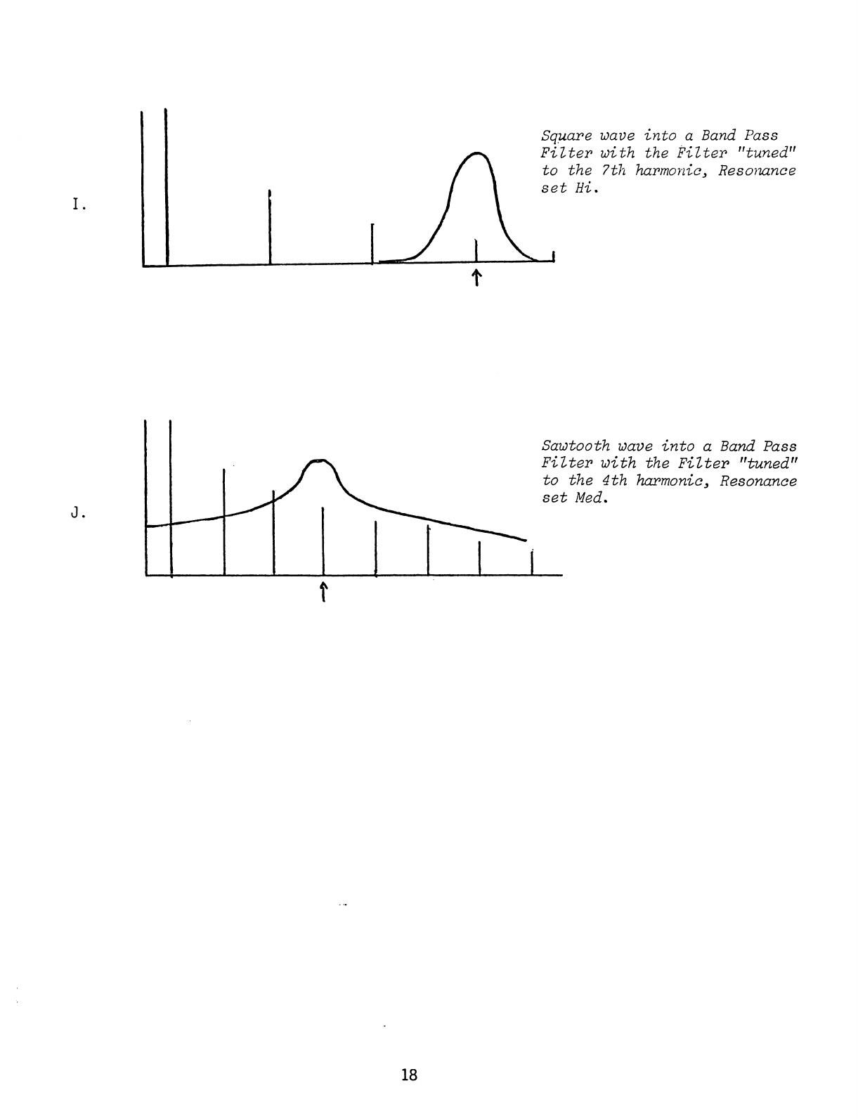
Square
wave
into
a
Band
Pass
Filter
with
the
Filter
"tuned"
to
the
3rd
harmonic>
Resonance
set
Lo.
17
Scan by Manual Manor
http://www.markglinsky.com/ManualManual.html
Square
wave
into
a
Band
Pass
Filter
with
the
Filter
"tuned"
to
the
7th
harmonic.
Resonance
set
Hi.
Sawtooth
wave
into
a
Band
Pass
Filter
with
the
Filter
"tuned"
to
the
4th
harmonic,
Resonance
set
Med.
18
Scan by Manual Manor
http://www.markglinsky.com/ManualManual.html

Before
continuing
to
the
next
modifier,
read
the
following
and
consider
it
in
the
context
of
your
experimenting.
Please
go
back
and
reconsider
the
Filter
in
this
light.
LO
PASS
FILTER.
The
Lo
Pass
Filter
lets
youvhear
all
the
overtones
below
its
Tune
slider's
setting.
In
general,
this
is
a
duller,
heavier
sound
than
any
of
the
other
Filter
modes.
If
this
control
is
set
too
low,
the
signal
will
be
very
weak.
Normally
the
Tune
control
in
this
mode
is
set
at
least
1/4
of
the
way
up
or
higher.
HIGH
PASS
FILTER.
The
Hi
Pass
Filter
lets
you
hear
all
the
overtones
above
its
Tune
slider's
setting.
In
general,
this
is
a
brighter,
buzzier
sharp
sound
than
any
of the
other
Filter
modes.
If
this
con
trol
is
set
too
high,
the
signal
will
be
weak
because
the
higher
overtones
don't
have
much
strength.
Normally
this
control
is
set
1/4
of
the
way
down
or
lower.
BAND
PASS
FILTER.
The
Band
Pass
Filter
lets
you
hear
all
the
overtones
around
its
Tune
slider's
setting.
In
general
this
sound
is
like
a
combination
of
Hi
Pass
and
Lo
Pass
-
dull,
but
brighter
than
Lo
Pass.
When
the
Resonance
slider
is
at
or
near
the
top
these
three
modes
sound
wery
similar.
19
Scan by Manual Manor
http://www.markglinsky.com/ManualManual.html

From
the
filter,
the
audio
path
continues
through
the
Modulator,
THE
MODULATOR.
The
Modulator
can
be
used
to
vary
the
timbre
of
the
sound
or
the
loudness
of
the
sound.
Whether
timbre
or
loudness
is
to
be
controlled
is
determined
by
the
position
of
the
Modulator!s
slider
and
switch.
The
slider
permits
you
to
preset
the
type
of
modulation.
The
switch
permits
you
to
select
the
source
of
modulation
-
either
Oscillator
2
or
the
Modulation
Oscillator.
The
settings
shown
below
illustrate
various
forms
of
loudness
and
timbre
controls
possible
with
the
Modulator.
Play
a
bit.
Don't hesitate
to
vary
the
sliders
marked with
arrows
as
you
play.
OUTPUTS
INPUTS
tO
PHONES
VOLTAGE
SUSTAIN
SEQUENCER
MIC
IN
MIC
VOL
i
I
I.3
l«i
FROCOMP'
SYNTHESIZER
ELECTRONIC
MUSIC
LABS..
INC.
VERNON.
CONN.
MOM
SOURCES
£
Z
1
NOISE
OSC
1
OSC
2
VOL
VOL
VOL TUNE
TT
TUNE
I
Irti
do-
MODIFIERS
TUNE
RESONANCE
MODULATOR
ENVELOPE
OUTPUT
UOOE
ATTACK
DECAY
SUSTAIN
VOL
t
B;
B;;
B:r
-B
::
RING
MODULATION
20
Scan by Manual Manor
http://www.markglinsky.com/ManualManual.html
Table of contents
Other EML Synthesizer manuals


