EMX Industries, Inc. CS303-L User manual
CarSense 303
O P E R A T I N G I N S T R U C T I O N S
4564 Johnston Parkway, Cleveland, Ohio 44128
P.
Sales Inquiries:
Technical Support:
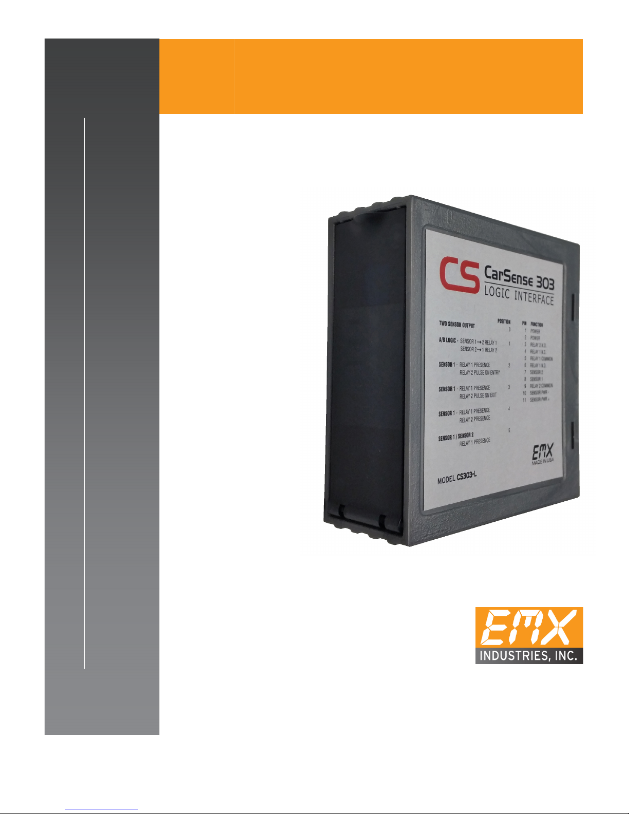
CarSense 303
L O I C I N T E R F A C E
4564 Johnston Parkway, Cleveland, Ohio 44128
P.
800 426 9912 F. 216 518 9884
Sales Inquiries:
salessupport@emxinc.com
Technical Support:
technical@emxinc.com
www.emxinc.com
CarSense 303
-
L
L O I C I N T E R F A C E
TM

CarSense 303-L™ Operating Instructions 1
Document no. 10310404 Revision 1.6 5-30-17
Contents
Cautions and Warnings
2
Product Overview
2
Specifications
3
Operation
3
Controls and Indicators
6
Connections
7
Troubleshooting
7
Installation
8
Ordering Information
8

CarSense 303-L™ Operating Instructions 2
Document no. 10310404 Revision 1.6 5-30-17
CE REQUIREMENT: Use CE rated power supply for CE co pliance providing
suppression as specified by EN61000-4-5.
Not to be used in safety applications.
IMPORTANT:
This product is an accessory or part of a system. Always read and follow the
manufacturer’s instructions for the equipment before connecting this product. Comply
with all applicable codes and safety regulations. Failure to do so may result in damage,
injury, or death.
WARNING:
DO NOT INSTALL THE SENSOR DIRECTLY INTO HOT ASPHALT, see installation section
WARNING:
Always use photoelectric protection when using the C 303 as a closing
detector on a parking arm operator to prevent accidental closing on a car.
Product Overview
The Car ense 303 Logic Interface (C 303-L) works with Car ense 303 Direct Burial (C 303-
DB) or Car ense 303 Flat Pack (C 303-FP) magnetoresistive sensors. Once the sensors
have been programmed using the Car ense 303 Controller (C 303-C-1), the sensors store
the settings and can operate independent of the controller.
The Logic Interface allows one or two sensors to be connected and provides 6 different
logic functions and two sets of relay outputs, one form A and one form C.
These functions include:
• AB Directional Logic
• Pulse on Entry
• Pulse on Exit
• Common Relay operation
• Discrete Relay operation
• Dual Relay operation
For more information regarding these functions and how they work, see page 4
Cautions and Warnings

CarSense 303-L™ Operating Instructions 3
Document no. 10310404 Revision 1.6 5-30-17
Specifications
Power Indicator Green LED
Detect Indicator 2x Red LEDs
Configuration Selector 10 position rotary switch
Outputs Relay 1: PDT (form C)
Relay 2: P T (form A)
Maxi u Output Ratings 1A @ 24 VDC/120 VAC
Operating Environ ent -40
o
C…82
o
C (-40
o
F…180
o
F)
0…95% relative humidity
Housing Material AB
Enclosure IP30
Power
(see Cautions and Warnings) 12-30 VDC or 24 VAC
Operating Current
(Standby/Detect)
One sensor connected: 22/35mA
Two sensors connected: 33/60mA
Supply Protection Circuitry Reverse polarity and fuse protected
Di ensions 73mm (2.9”) x 38mm (1.2”) x 78mm (3.1”)
Weight 0.25 lbs. (113 g)
Connector 11 pin male connector (JEDEC B11-88)
NOTE: Refer to Car ense 303 Operating Instructions for operation and installation of
controller and sensor.
Operation
Power Up
Upon power up the detector initializes: all three LEDs will flash on, then off. The green
LED indicates that the detector is powered and operational. Relay1 and Relay2 LEDs
indicate when Relay1 or Relay2 is activated, respectively.
Note that the sensor must be installed and programmed using a C 303-C-1 prior to
connection to the C 303-L. The C 303-L only monitors the sensors’ NPN outputs and
cannot be used to change operation settings in the sensor.
Specifications

CarSense 303-L™ Operating Instructions 4
Document no. 10310404 Revision 1.6 5-30-17
Operation (continued)
Set the Configuration Selector Switch
Presence detection is determined by the settings programmed to the CS303-D / CS303-FP
connected. Refer to the CS303 Operating Instructions when installing the sensor(s) (CS303-D
/ CS303-FP) to determine sensor settings appropriate for your application.
Rotary
Switch Mode ehavior
0 Discrete Relays Relay1: Active while Sensor1 is active
Relay2: Active while Sensor2 is active
1 A Directional Logic
Relay1: Activates when Sensor1 and then
Sensor2 activates
Relay2: Activates when Sensor2 and then
Sensor1 activates
2 Pulse on Entry Relay1: Active while Sensor1 is active
Relay2: 500ms pulse when Sensor1 activates
3 Pulse on Exit Relay1: Active while Sensor1 is active
Relay2: 500ms pulse when Sensor1 deactivates
4 Dual Relays Relay1: Active while Sensor1 is active
Relay2: Active while Sensor1 is active
5 Common Relay
Relay1: Active while Sensor1 or Sensor2 is active
Relay2: 500ms pulse when Sensor1 or Sensor 2
activate
6 … 9 Invalid Relay1: nactive
Relay2: nactive
Discrete Relays
While operating in Discrete Relays mode, Relay1 will activate and remain active while a
vehicle is detected by ensor1. Relay2 will activate and remain active while a vehicle is
detected by ensor2.
AB Directional Logic
AB Directional Logic mode is capable of determining the direction of travel of a vehicle
using two sensors. Two sensors are installed in the direction of travel to provide input.
If a vehicle is detected by ensor1 and then ensor2, Relay1 will activate and remain
active while the vehicle is detected by ensor2.
If a vehicle is detected by ensor2 and then ensor1, Relay2 will activate and remain
active while the vehicle is detected by ensor1.
When using the A Directional Logic function, the sensors should be installed 1 meter (40”)
apart.

CarSense 303-L™ Operating Instructions 5
Document no. 10310404 Revision 1.6 5-30-17
Operation (continued)
Pulse on Entry
Pulse on Entry provides mode presence (Relay1) and pulse (Relay2) outputs. When a
vehicle is detected by ensor1, Relay1 will activate and remain active while the vehicle
is present, Relay2 will activate for 500ms and then remain inactive.
Pulse on Exit
Pulse on Exit mode provides presence (Relay1) and pulse (Relay2) outputs. When a
vehicle is detected by ensor1, Relay1 will activate and remain active while the vehicle
is present, Relay2 will be inactivate until the vehicle is undetected, then Relay2 will
activate for 500ms and then deactivate.
Dual Relays
Dual Relays mode allows for the operation of both Relay1 and Relay2 by ensor1. While
a vehicle is detected by ensor1, both Relay1 and Relay2 will be active.
Co on Relay
Common Relay mode allows for the operation of Relay1 and Relay2 by both ensor1
and ensor2. When a vehicle is detected by either ensor1 or ensor2, Relay1 will
remain active while the vehicle is detected, Relay2 will activate for 500ms and then
remain inactive.
Invalid
While the rotary switch is set to positions 6, 7, 8, or 9, the relays will remain inactive and
all three LEDs on the unit will flash on and off once per second.
CarSense 303-L™ Operating Instructions 6
Document no. 10310404 Revision 1.6 5-30-17
0
5
6
1
2
3
7
8
9
4
POWER
RELAY
1
RELAY
2
Controls and Indicators
CONFIGURATION SELECTOR
Function Position 0…9
Discrete Relays 0
AB Directional Logic 1
Pulse on Entry 2
Pulse on Exit 3
Dual Relays 4
Co on Relay 5
Invalid 6…9
POWER
RELAY 1
RELAY 2
Power On/Off
Relay 1 On/Off
Relay 2 On/Off

CarSense 303-L™ Operating Instructions 7
Document no. 10310404 Revision 1.6 5-30-17
Connections
NOTES: 1) Refer to Operator Instruction for power and relay/control connections
2) Protect RED and GREEN wires fro the sensor using electrical tape or other
suitable electrical insulation
Troubleshooting
Symptom Possible Cause Solution
All LEDs lash, one second
cycle Invalid rotary switch selection Set rotary switch to a valid setting
(0-5)
Red LED lashes, relay
clicks, unstable
Poor connection for Sensor1 or
Sensor2
Check and fix connection
If only one sensor is used, set rotary
switch to a valid position for 1 sensor
Green and Red LEDs lash
simultaneously Insufficient supply voltage
Make sure the power supply is
working correctly and properly rated
according to connections table
(see above)
Pin Description Sensor
#1 wire
Sensor
#2 wire
1 Power (12 – 24 VDC/VAC) - -
2 Power (12 – 24 VDC/VAC) - -
3 Relay2 – NO - -
4 Relay1 – NC - -
5 Relay1 – COM - -
6 Relay1 – NO - -
7 Sensor2 Input - White
8 Sensor1 Input White -
9 Relay2 – COM - -
10 Sensors Power ( – ) Blue Blue
11 Sensors Power ( + ) Brown Brown

CarSense 303-L™ Operating Instructions 8
Document no. 10310404 Revision 1.6 5-30-17
1. Refer to Car ense 303 Operating instructions for installation and set-up of the
sensors for proper operation. All settings are stored in the sensors for stand-alone
operation.
2. C 303-L monitors the NPN outputs from the sensors and does not provide the
ability to change sensor (C 303-DB / C 303-FP) settings.
3. When using the AB Directional Logic function, the sensors should be installed 1
meter (40”) apart in the axis of travel.
4. When wiring the sensors to the C 303-L:
a. The brown wire from both sensors goes to pin 11 on the C 303-L
b. The blue wire from both sensors goes to pin 10 on the C 303-L
c. The white wire from one sensor goes to pin 8 ( ensor1 Input) on the C 303-L
d. The white wire from the other sensor goes to pin 7 ( ensor2 Input) on the
C 303-L
e. Protect RED and GREEN wires from the sensor using electrical tape or other
suitable electrical insulation
Ordering In ormation
• CS303-L CarSense 303 Logic Inter ace
Installation

CarSense 303-L™ Operating Instructions 9
Document no. 10310404 Revision 1.6 5-30-17
Warranty
EMX Industries Incorporated warrants all products to be free of defects in
materials and workmanship for a period of two years under normal use and
service from the date of sale to our customer. This warranty does not cover
normal wear and tear, abuse, misuse, overloading, altered products, damage
caused by incorrect connections, lightning damage, or use other than intended
design.
There is no warranty of merchantability. There are no warranties expressed or
implied or any affirmation of fact or representation except as set forth herein.
EMX Industries Inc. sole responsibility and liability, and the purchaser’s
exclusive remedy shall be limited to the repair or replacement at EMX
Industries option of a part or parts found not conforming to the warranty. In
no event shall EMX Industries Inc. be liable for damages, including but not
limited to damages resulting from non-conformity, defect in material or
workmanship.
Effective date: January 1
st
, 2002

CarSense 303-L™ Operating Instructions
Document no. 10310404
United tates of America
Technical upport: (216) 834
salessupport@em
Revision 1.6
4564 Johnston Parkway
Cleveland, Ohio 44128
United tates of America
www.emxinc.com
Technical upport: (216) 834
-0761
ales: (216) 518-9888
Fax: (216) 518-9884
salessupport@em
xinc.com
10
5-30-17
Table of contents


