@crown®* System®Product Reference
videacontrolvoltageforexternaluseas
well as an entry point for a control volt-
age into the system.
•CrownBusloopconnector(G).Ituses
a four pin removable barrier block.
SETUP
Toaccessthebatterycompartmentand
setup switches slide the battery cover
off the back panel. Before inserting a
battery configure the baud and ad-
dress switches as necessary. Note that
no two PSI units on the same loop may
have the same loop address, valid ad-
dressesrangefrom 1 to250.Baud may
be set for 38,400, 19,200, 9,600, or
4,800.
IQ2SUPPORT
TheIQ-PSIisanIQ2componentand,as
an interface, it supports both IQ2and
legacy protocol.
SPECIFICATIONS
Internal Controls — One 8-segment DIP
switch to set the address, one 4-seg-
ment DIP switch to set RS232 baud
rate.
External Controls — Power on-off.
Connectors — One 4-pin “Euro-style”
removable barrier block Crown Bus
connector, one 3-pin “Euro-style” re-
movablebarrierblockauxportconnec-
tor, one female 9-pin RS232 connector
on attached cable, one male coaxial
+10VDC external power input jack.
Indicators — Green Enable LED shows
unit is powered and switched on and a
yellow Data LED that indicates data
transmitted to/from the unit or may be
forced on via software.
BAUD
38,400
19,200
9,600
4,800
SWITCHES
1
ON
OFF
OFF
OFF
2
OFF
ON
OFF
OFF
3
OFF
OFF
ON
OFF
4
OFF
OFF
OFF
ON
Power — Standard 9 VDC battery or
external 10 VDC supply.
Finish—Moldedblackhigh-impactsty-
rene.
Crown Bus Isolation — Data is optically
coupled to 20 mA current loop.
Data Rate — 38.4K baud on Crown Bus
loops; 4.8 to 38.4K baud to computer.
Data Format — Serial, binary, asynchro-
nous, 1 start bit, 1 stop bit, 8 data bits,
no parity.
Crown Bus Interface Type — Isolated 20
mA current loop.
PC Interface Type — RS232.
Operation — Half duplex.
Crown Bus Transmission Distance — 300
to 3000 feet (90 to 900 m), depending
on wire type, size, and capacitance.
Typically1000feet(300m)withshielded
twisted pair 26AWG or larger; extend-
able via IQ Repeater.
Transmission Distance RS232 — 50 feet
(15 m).
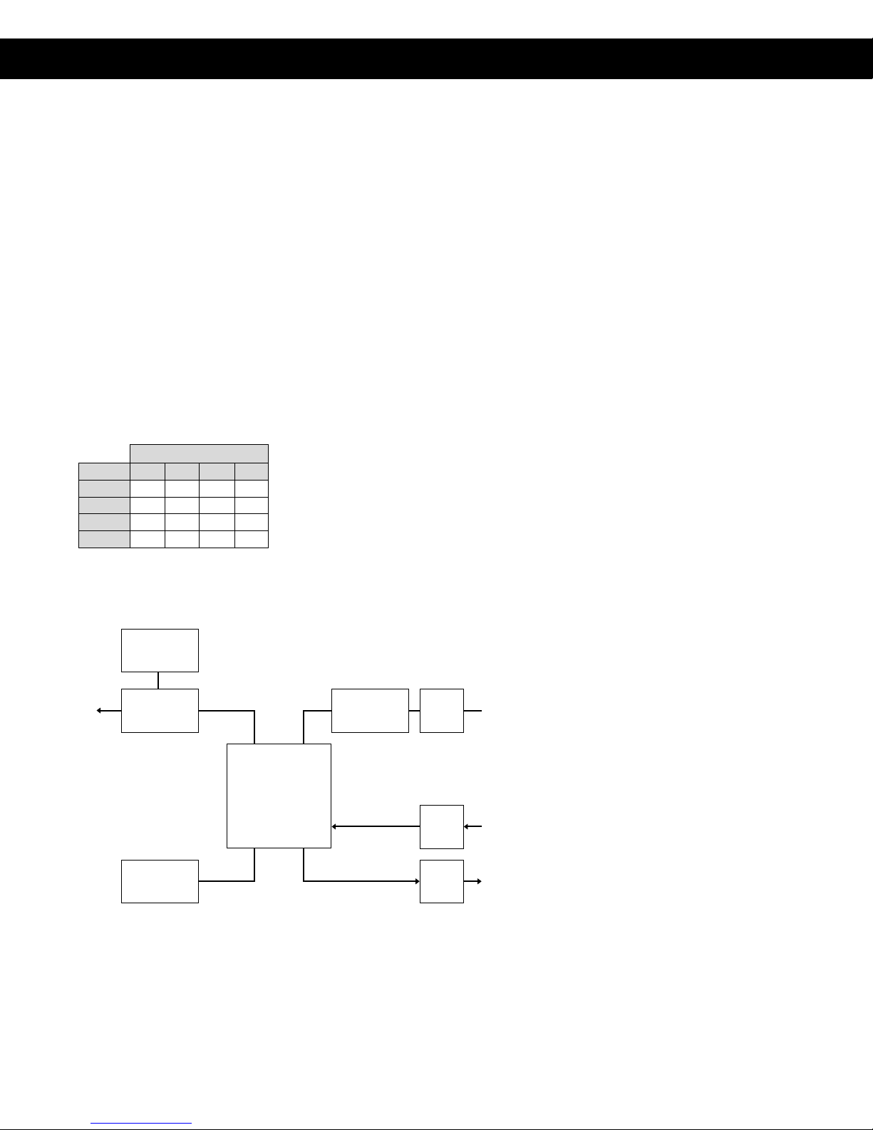
RELAYSOPTOCOUPLER
MICROPROCESSOR
BUFFER
BUFFER
BAUD RATE
GENERATOR
IQ ADDRESS
SWITCH
CROWN BUS
AUX
AUX
BAUD RATE
GENERATOR
BAUD RATE
GENERATOR
RS-232
Guaranteed Excellence
@crown
Crown International, Inc.
PO Box 1000 Elkhart, IN 46515-1000
Ph. 800-342-6939/219-294-8200
Fax 219-294-8301
Internet: www.crownintl.com
Trademark Notice:Trademark Notice:
Trademark Notice:Trademark Notice:
Trademark Notice:
IQSystem
®
isaregisteredtrademarkof
Crown International Inc.
Baud Rate Selection
IQ-PSI Pocket Serial Interface (Page 2 of 2)
PSI Basic Block Diagram


