Endecotts Fluid Bed Dryer User manual

USER GUIDE
FLUID BED DRYER

The Fluid Bed Dryer User Guide
Contents
Chapter 1 - Introduction
Customer Service
Using this Manual
Safety Instructions
Safe use of Instrument
Setting up the Instrument
Instrument Description
Drying Tubs and Accessories
Special notes on accessories
Instrument Components
Applications
Optimal Bed Depth
Basic Principles of Fluidised Beds
The Drying Process
Page 1
Page 1
Page 2
Page 3
Page 3
Pages 4 - 6
Page 6
Page 7
Pages 8 -9
Page 10
Pages 10-11
Page 11
Pages 12 -14
Chapter 2 –Operating Procedure
Operating –Overview
Setting the Conditions
Setting the Timer Control
Setting the Temperature Control
Setting the Blower
Starting and stopping
General
Optional Extras
Humidity / Temperature Probe
Installing a Pulse Flow Device
Operation with a Pulse Flow Device
Page 15
Page 16
Page 16
Page 17
Page 17
Page 18
Page 19
Page 20
Pages 20 -21
Page 21
Page 22
Chapter 3 - Maintenance
General Maintenance
Air filters
Replacement of Flange “O” Ring
Replacement of Outlet Filter on the instrument
Power on Checks
Fuses
Specification
General Advice
Page 23
Page 23
Page 24
Page 24
Page 24 - 25
Page 26
Page 27
Page 28

Introduction
Chapter 1
Customer service
Thank you for purchasing Endecotts Fluid Bed Dryer
If you need spare parts or service please contact your local distributor in the
first instance: or:-
Endecotts Ltd
9 Lombard Road
London SW19 3TZ United Kingdom
Tel +44 (0)20 8542 8121
Fax +44 (0)20 8543 6629
E mail sales@endecotts.com
If you require spare parts please have the following information ready: -
Serial number of the instrument.
Part numbers and /or exact descriptions of the items required.
Quantity required.
Date required and any special shipment request.
Delivery address.
Purchase request / order reference.
If you require technical assistance please have the following information
ready: -
Serial number of the instrument
Description of the problem
Address and telephone number
Contact name
Using this Manual
The information contained in this manual will assist you in getting the best
from your Fluid Bed Dryer. The text accurately describes the original build
specification, the drawings and illustrations are intended for general
reference only and are not necessarily accurate in every detail. Dimensions
and characteristics are not to be changed without prior notice.
- 1 -

Introduction
Chapter 1 (continued)
The user is responsible for updating the manual with any bulletins from
Endecotts and to reflect any changes or modifications made by the customer.
Endecotts cannot be held responsible for the conditions of use and changes to
the instrument that are beyond its control.
No parts of this manual or any other documents supplied with this instrument
may be reproduced or transmitted without the prior written consent of
Endecotts.
Safety Instructions
Throughout this manual the reader’s attention is drawn to specific safety
instructions as follows: -
WARNING!
A warning alerts the reader to a personnel hazard. Failure to act on the
warning may result in death or injury.
CAUTION!
A caution alerts the reader to a hazard. Failure to comply with the
caution may result in damage to the instrument or product.
NOTE:
A note provides additional information that should be given special
attention.
- 2 -

Introduction
Chapter 1 (continued)
Safe Use of Instrument
Endecotts makes every possible effort to ensure that the instruments it
supplies are designed and constructed to be safe and without risk to health
or property when used properly. In accordance with relevant EU Directives,
they are marked with the CE symbol to indicate they comply with all
relevant European safety and hygiene requirements. However, please note,
that instruments can cause injury if you are careless and do not follow the
operating instructions.
Ensure that you and all others working nearby know the location of the
instrument controls and how to use them; especially the front panel
Operations On/Off button and the Power On/Off switch located on the
back of the instrument.
Ensure that you have read the relevant parts of this manual before attempting
to use or work with the Fluid Bed Dryer. For your own safety and those of
others, please ensure the operator or personnel in charge of the location has
received proper training.
Setting Up the Instrument
The instrument will arrive packed in a purpose designed box having a packing
slip. Ensure that all the system components arrive s a f e l y . To f o r m an
o p e r a t i n g s y s t e m t h e r e a r e t h r e e components which are
required. The instrument, the tub assembly, and a suitable filter for the
tub assembly.
The location of the dryer should be chosen for the intended use. For use with
samples where dust may be generated or for frequent use on samples with
high moisture content, we suggest positioning the dryer in a fume hood.
The rear panel of the instrument and the underside have air filters provided
for supplying cooling air for the inside of the cabinet. The rear panel also has a
stainless steel mesh filter provided for the inlet air used for drying the sample.
Ensure there is enough space adjacent to these filters to allow air to enter the
instrument.
- 3 –
Introduction
Chapter 1 (continued)
Instrument Description
The dryer is of simple, compact design, conveniently portable and easy to
operate, the only requirement being a mains power supply.
The source of power should be within the reach of the instrument lead so
that no extension wires are required. The instrument contains the air
distribution system, heater element, thermostat, and electrical controls.
There are many types of tub assemblies to choose from which can be used
with the Fluid Bed Dryer. Please contact Endecotts for details.
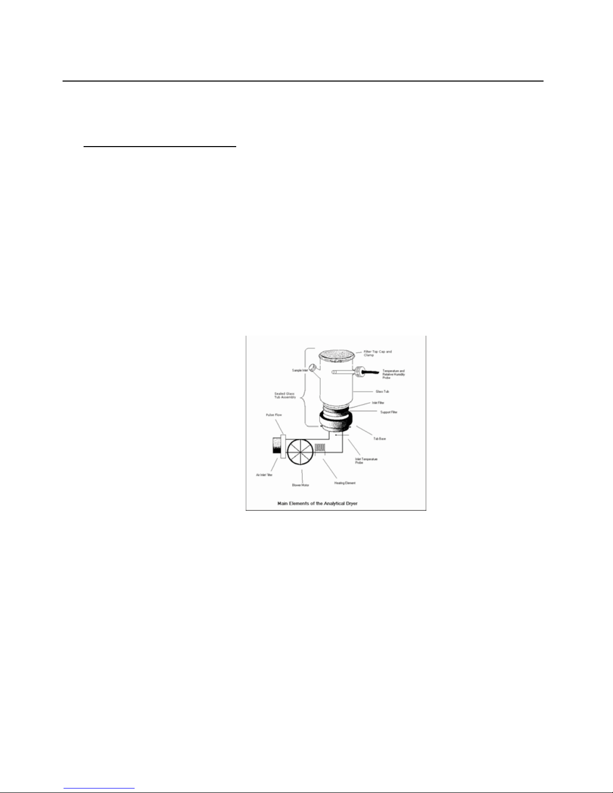
The FBD incorporating the full range of options is illustrated below. This
dryer enables the operator to have complete control a compile a record of
the drying process. The main components are shown below: -
Air is drawn in through a Stainless Steel Inlet filter in the back of the
instrument and blown by the centrifugal fan over a 2kW electrical heater and
through stainless steel filter gauze at the top of the dryer body. A Pulse Flow
Unit (optional extra) is situated after the inlet filter, which can intermittently
shut the inlet air on and off, which acts as an additional means of fluidising a
difficult sample. A 5 litre sealed glass tub is shown having a tub base
which attaches to the instrument by means of a bayonet fitting. There is an
“O” ring seal between the tub assembly and the instrument. At the inlet of
the tub assembly, there is a 60 mesh stainless steel support filter and a fine-
mesh nylon filter.
- 4 -

Introduction
Chapter 1 (continued)
Instrument Description cont/…
These filters retain the sample in the tub assembly while assuring a uniform
distribution of air enters the assembly. A filter top cap is clamped on to the
top of the tub by means of a clamp and seals on a silicon “O” ring which also
keeps the sample particles from escaping the tub assembly. The wide range
of tub assemblies which are available are designed to match the variety of
sample types and drying applications.
To facilitate the addition of a sample a side port is provided having a
sealing screw cap. In addition to an inlet temperature probe, which is part of
the thermostat control, a temperature / humidity probe is also available for
the outlet of the tub assembly.
The above dryer can be used as a stand alone unit, with full control of
the flow rate, inlet temperature, and time of drying. The values of the inlet
set temperature, actual inlet temperature, outlet temperature and humidity
and time remaining in the drying cycle can be obtained by directly reading
from the front panel.
- 5 -

Introduction
Chapter 1 (continued)
Instrument Description cont/…
DRYING TUBS and ACCESSORIES
The 5 Litre Sealed Glass Tub having a sample port and a sensor port is the
standard tub assembly for the Fluid Bed Dryer. It
allows full utilisation of the analytical, data capture and storage, and
programming control feature on the dryer. There are many
other types of tub assemblies each having their own type of filter which can be
used on the instrument.
TUB ASSEMBLIES AND FILTERS
LARGE TUB ASSEMBLIES
2 LITRE STAINLESS STEEL TUB & BASE
2 LITRE GLASS TUB & BASE
5 LITRE STAINLESS STEEL TUB & BASE
5 LITRE GLASS TUB & BASE
USE LARGE FILTER BAGS AVAILABLE IN NYLON,
TERYLENE, POLYPROPYLENE, AND NOMEX
5 LTR SEALED GLASS TUB & BASE USE TOP CAP FILTERS
AVAILABLE IN SS (60, 250, 500 MESH), 3 MICRON
POLYESTER
MINI TUB ASSEMBLIES
USE FOUR MINI TUBS WITH A MINI TUB ADAPTOR MINI SS TUB
MINI GLASS TUB
USE MINI FILTER BAGS
AVAILABLE IN NYLON, TERYLENE, POLYPROPYLENE, AND
NOMEX
500 350 33 MINI SEALED GLASS TUB
USE MINI DISC FILTERS
AVAILABLE IN NYLON, SS (60, 250, AND 500 MESH),3 3 3
3 MICRON POLYESTER
- 6 -

Introduction
Chapter 1 (continued)
Special Notes on the Accessories
Only the 5 litre glass tub assemblies, both those using filter bags and the sealed
variety, can have an inlet for the outlet humidity and temperature probe. Only
these tubs can fully utilise all the features on the Fluid Bed Dryer.
The glass tubs have an advantage in the operator being able to see the sample as
it dries. The optimum flow rate is easy to select judging by the appearance of the
fluidised sample. The operator is often able to estimate the state of dryness and
guess the shape and size distribution of the particles simply by the appearance of
the sample flowing in the tub. The main advantage of the stainless steel tubs is
durability. High-grade stainless steel is used since the process requirements
usually call for high product purity and good chemical and corrosion resistance at
high temperature. Other specialised tub assemblies which can be used on the FBD
include a Particle Classifier and a Sieve Dryer.
The mini tubs are 250ml in capacity and can be used effectively on samples
weighing from 5 to 50 grams per tub. Four tubs can be dried simultaneously.
The decision to go to sealed tubs is based simply on particle size. Below 45
microns, we suggest you go to a sealed tub.
The 3 micron polyester filters can be used for the mini tubs as well as the 2 and 5
litre tubs. These filters are effective for 5 to 25 micron particles. Please note that
these filters greatly reduce the flow rate of air through the sample. Drying times
normally occurring between 10 to 30 minutes can take up to several hours using
these small pore size filters. Furthermore, the use of these filters may even hinder
the mixing of sample particles during drying. Many of the main advantages of fluid
bed drying may be lost. If in doubt, Endecotts offer to do an initial study on your
sample which will ensure proper accessories are chosen for the application.
A wet sample should occupy about 1/3 of the tub assembly volume. As it dries
and the density drops, the apparent volume will increase to about ½ the volume.
Tubs should be purchased that are 3 x the volume of the sample size.
- 7 -

lower
Set
Value
Cubic
Metres per
Min
Cubic Feet
per Min
Metres per
Second
Feet per
Minute
Litres per
Second
0
0.13
4.59
0.35
68.6
2.17
10
0.32
11.30
0.86
169
5.33
20
0.50
17.66
1.34
264
8.33
30
0.70
24.72
1.88
369
11.67
40
0.89
31.43
2.39
470
14.83
50
1.07
37.79
2.87
564
17.83
60
1.25
44.14
3.35
659
20.83
70
1.45
51.21
3.89
765
24.17
80
1.64
57.92
4.40
865
27.33
90
1.82
64.27
4.88
960
30.33
100
2.00
70.63
5.36
1055
33.33
Introduction
Chapter 1 (continued)
The Instrument Components
The Fluid Bed Dryer incorporates an electrical heater, temperature
controller, timer and a powerful air blower fan. There are, however,
significant improvements over previous models. All the controls on the
front panel are on a printed membrane with pressure controlled contacts
which prevent the ingress of fine powder. The cooling air, as well as the air
for drying the sample are filtered. This eliminates possible faults related to
powder getting inside the instruments and switches.
The air blower is controlled by a thyristor circuit to give a smooth variation
over a wide range of motor speeds, as in previous models. On the
Fluid Bed Dryer, however, the blower motor speed is monitored and a
feedback loop assures the blower motor speed is maintained regardless
of surges in power supply or effects of a heater being switched on and
off. This achieves a more controlled fluidisation and allows us to monitor
the volume of air per time used in the drying process. A seal between the
tub assembly and the instrument ensures all the air that is measured goes
through the sample. Each instrument is calibrated for flow rate output
during manufacturing.
lower
Set
Value
Cubic
Metres per
Min
Cubic Feet
per Min
Metres per
Second
Feet per
Minute
Litres per
Second
0
0.13
4.59
0.35
68.6
2.17
10
0.32
11.30
0.86
169
5.33
20
0.50
17.66
1.34
264
8.33
30
0.70
24.72
1.88
369
11.67
40
0.89
31.43
2.39
470
14.83
50
1.07
37.79
2.87
564
17.83
60
1.25
44.14
3.35
659
20.83
70
1.45
51.21
3.89
765
24.17
80
1.64
57.92
4.40
865
27.33
90
1.82
64.27
4.88
960
30.33
100
2.00
70.63
5.36
1055
33.33
The 2 kW heater element is controlled by a thermostat system. The
maximum achievable temperature is 200 degrees Centigrade, but this is
determined and limited by the flow rate that and the power supply.
- 8 –

Introduction
Chapter 1 (continued)
Warning!
When Operating a Dryer above 65°C we recommend making a copy of the
following warning sign so that it can be displayed next to the instrument
and tub assembly.
Stick on thermal labels can be also provided for all 2 and 5 litre tub
assemblies on request and should be positioned in the most visible location if
the instrument will be he used at elevated temperatures.
The use of microprocessors in the instrument allows us to control the
temperature during heating and cooling the sample to within a few degrees.
Note: -
Good temperature control is only obtained when a tub assembly is in
position on the instrument. Without a tub assembly, the air flows
without resistance and a wide deviation may be observed between the
set temperature and that actually achieved.
A pulse flow device may be added to the unit as an optional extra. The FBD
has a pulser which is retrofitable and is positioned externally at the air inlet.
- 9 -

Introduction
Chapter 1 (continued)
Applications
The wide range of materials that can be dried includes fine powders, coarse
particles, crystals, granules, slurries or pastes (after decanting, or pre-
drying or by spraying into bed of initially dried material). Samples with
moisture content up to 80% such as some polymers, dyestuffs and molecular
sieves can also be dried with the provision that they remain solid in nature at
these high moisture levels. An operator can also dry heat sensitive materials,
such as foodstuffs e.g. peas, wheat and lentils, since they may be dried at
relatively low temperatures. If traces of volatile organic compounds or
hazardous fumes are generated during the drying process, drying should be
conducted in a fume cupboard.
Warning:-
The FBD is not an explosion proof instrument and therefore samples having
volatile compounds that are flammable or able to reach their flash point
should not be used with this dryer.
Because of the high heat and mass transfer rates obtainable, drying times
for the Fluid Bed Dryer are much less than for the more traditional methods
available in laboratories such as oven or vacuum drying. Many materials can
be dried in less than 15 minutes.
Optimal Bed Depth
The optimal bed depth which is related to the amount of wet sample which
can be used is that at which the sample can be fluidised smoothly at
the required temperature by a set air velocity. This normally is
equal to the sample filling approximately 1 /3 of t h e t u b b e i n g
u s e d f o r d r y i n g . (The advantages of the fluid bed dryer can however
be realised even if the sample lurches and mixing in a non-ideal manner).
As drying proceeds with most samples, the sample becomes less dense and
less sticky”and the bed becomes easier to fluidise. The apparent volume of
the fluidised sample will change from 1/3 (75 mm bed depth) to ½ (150 mm
bed depth) of the volume of the tub assembly. Normally, the air velocity will
be progressively reduced as the sample dries.
- 10 -

Introduction
Chapter 1 (continued)
Due to the complexities of the mixing and drying process, the optimal amount
of sample to use is best determined by trial and error.
The pulse flow works most effectively on “stringy” samples that will not mix,
particularly when they are wet. The short blasts of air from the pulse flow
essentially mixes the sample with each pulse. This is usually only required until
the sample loses its external moisture, after which we find most samples will
fluidise more easily. Using a pulse flow may not show any improvement in
drying more ideal, easier to mix samples.
Basic Principles of Fluidised Beds
When a stream of gas is passed upwards through a bed of material at a certain
velocity the bed will first expand, then become suspended and agitated by the
gas stream to form a fluidised bed.
This has the appearance of boiling liquid due to the formation ofmany small
bubbles at the surface of the sample, the so-called “bubbling fluidisation”.
Ideal fluidisation is achieved only with spherical particles of a narrow size
distribution range and with the appropriate amount of sample with the
optimal flow of gas. The optimum operating gas velocity for bubbling
fluidisation lies above the minimum fluidising velocity but below the velocity
of entrainment of the material. Needless to say, this ideal is not often
achieved with real samples. With real samples and maximum amounts of
material to dry, the other forms of drying are more generally obtained.
At higher gas velocities, larger bubbles and plugs of material are formed
resulting in a more violent type of fluidisation called slugging or spouting.
Particles that are needle shape (have a large aspect ratio) are more likely to
give “spouting fluidisation” with the spout arising from the centre of the
sample and falling back down along the outer surface of the sample near the
tub.
- 11 -

Introduction
Chapter 1 (continued)
The Drying Process
If water is added to a dry sample, it is absorbed by particles until the point
at which the particles become saturated. The saturation point is known as
the Critical Moisture Content.
The CMC is characteristic of the sample material, and the initial water which
is incorporated into the particle is held as internal moisture. If placed in a
sealed container, a sample containing internal moisture will become
homogeneous. The further addition of water past saturation will become
external moisture. External moisture is heterogeneous by nature, being pools
of water lying in between the saturated particles. The drying process
reverses the procedure, as external moisture is first removed.
A bed of wet material fluidised by a heated air stream provides ideal
conditions for drying. The very efficient contact between gas and solid
particles due to the turbulence of the bed results in high heat transfer rates
causing rapid evaporation (mass transfer) of moisture which is carried away
with the exit air. This process has a high thermal efficiency because most
of the heat input is used in vaporising the moisture and the exit air only
rises in temperature as drying of external moisture nears completion.
External moisture is the first to be removed, and it is removed at a rate
controlled by the flow rate and temperature and is not influenced by the
presence of the solid constituent in the sample. Following this, the internal
moisture is removed. The rate of internal moisture removal is usually limited
by the diffusion of water from within the particle, and less directly
influenced b process parameters.
Continuous and thorough mixing of the sample while drying ensures that the
temperature and moisture content are uniform throughout the sample and
the drying process is reproducible and the end product is homogeneous.
- 12 -

Introduction
Chapter 1 (continued)
The Drying Process cont/…
The process can be conducted at relatively low temperatures and there is little
abrasion, since the particles are separated by air bubbles. The drying process
can be analysed to show the amount of internal and external moisture. When
external moisture is removed, drying can be conducted quickly, since the
temperature is kept low by the evaporation of water. When internal water is
removed, drying should be conducted very slowly to give time for the water to
diffuse out of the particles. The temperature control and understanding of the
critical aspects of drying ensures that heat-sensitive materials can be treated
with care.
The knowledge gained from lab scale fluid bed drying is directly applicable to
industrial fluid bed dryers, since the same principles apply. Characterising a
product in the laboratory provides useful information for continuous and
batch scale dryers in the plant. Studies in the lab are useful for designing plant
scale fluid bed dryers.
Typical Applications
1. Drying of a material to a given moisture content using
reproducible drying parameters.
2. Fluidising curves give the variation of pressure drop with air flow-
rate.
3. Establishing the conditions required to achieve minimum and the
more normal operating fluidisation velocity.
4. Determination of drying curves indicating Critical Moisture to
assess Internal and External Moisture and show feasibility of
fluidised bed drying of a material on an industrial scale. Also
established best industrial scale dryer to use. (Drying curves are
relevant to the mechanism of drying. They may be used as a basis
for heat and mass.
- 13 -

Introduction
Chapter 1 (continued)
The Drying Process cont/…
5. Calculation of heat transfer coefficients for different conditions
relevant to dryer design and comparison of fluidised beds with other drying
methods.
Other applications include: -
Drying small particulates, drying particulates with a wide particle size range,
drying down to a particular moisture concentration, analysis of moisture,
rapid drying, homogenising samples, separating particles based on density,
coating samples, etc.
A most important application of fluid bed drying is determining a drying curve
for a sample. A drying curve, i.e. a plot of moisture loss over time, shows the
drying characteristics of the material. We can derive the drying rate,
constant rate of moisture loss (external moisture) and falling rate periods
(internal moisture), drying times, equilibrium moisture content and critical
moisture content and heat transfer coefficients. All valuable information in
characterising a sample and designing an industrial drying process.
- 14-

Operation
Chapter 2
Operating: - Overview
The Fluid Bed Dryer has been designed to make reproducible drying easy.
The instrument should be connected to the power source and turned on from
the mains switch on the back of the instrument.
When turning the mains power on, all the lights on the front panel flash on
and off while the instrument initialises. Following this, the Version number of
the Software held within the instrument is displayed momentarily (U103 at
time of going to press). The instrument starts up in standby mode,
displaying the last settings for the blower speed, timer and temperature.
The operator can set the functions and power the instrument on and off from
the front panel.
There are four sections on the front panel namely to set the drying time, set the
inlet temperature (SV), set the blower speed and turn the instrument on and off.
Each will be discussed in turn.
- 15-

Operation
Chapter 2 cont/…
Setting the Conditions
In standby mode, the variables of time, inlet temperature and blower
speed can be set prior to running the instrument. There are symbols
indicating the four sections. A blue clock face icon indicates the timer, the
yellow radiation symbol icon indicates the heater, and a fan blade icon
indicates the blower and finally the power section having on/off symbols as
buttons.
If the display for the timer or heater sections are not illuminated when the
instrument is turned on, this simply indicates these functions were not used
on the last occasion when the instrument was operated. They can be turned
on by a short press of their icon buttons.
The set-up procedure for operation consists of the following: -
Section 1 - Setting the timer.
A blue flashing light above the timer icon indicates that the timer is ready to
receive an input setting. Pressing the (+) or (-) positions adds or subtracts
minutes to the timer. The display is hours and minutes, with a minimum
setting of 1 minute and a maximum setting of 9 hours and 59 minutes.
Pressing the blue clock face at any stage turns the timer off. The timer
section is shown below.
Section 1
- 16-

Operation
Chapter 2 cont/…
Section 2 - Setting the temperature.
A green flashing light above the “Heater Symbol” indicates that it is ready to
receive a temperature value. The red light (SV) is illuminated in the lower left
hand corner of the digital display shows that the “Set Value” of the
temperature is being displayed.
Section 2
The (+) and (-) buttons allow the set value to be adjusted from 20.0 up to
199.9 deg Centigrade. Pressing the Heater Symbol at any stage in the
operation of the instrument turns the temperature control off. (see p19 last
para)
Section 3 - Setting the blower.
The blower function always turns on when the power is supplied to the
instrument and the flashing green light above the blower icon flashes
indicating an input adjustment to the blower speed can be made. The (+) and
(-) switches allow adjustment between 2 and 100%, which is displayed. The
blower speed below 10% is considered less accurate in its correlation to an
absolute flow rate).
Section 3
The blower can never be entirely turned off while the instrument is in
operation which is a safety feature which prevents overheating. (The unit also
has an over temperature cut off switch as a further precaution against
overheating).
- 17-

Operation
Chapter 2 cont/…
Section 4 - Starting and Stopping the Dryer.
The dryer can be turned on, to operate according to its pre-set conditions,
by pressing the green switch below the power light. Section 4
Pressing the red switch stops the dryer operation and displays the last set
values. Pressing the start again refreshes the timer which begins counting
down from the original set time. When the dryer reaches the end of a
timed cycle, it automatically goes into standby mode.
The ‘power’ light changes from a yellow colour in standby to a red colour
during operation.
All the (+) and (-) adjustments can be accelerated by holding down the
switches.
- 18-
Table of contents
Popular Dryer manuals by other brands

Staber Industries
Staber Industries HXD2304E Operator's manual

Blomberg
Blomberg TKF 8451 manual

Bosch
Bosch WTG86400AU Installation and operating instructions

montpellier
montpellier TCS8 Installation and operating instructions

American Dryer Corp.
American Dryer Corp. AD-310 parts manual

LG
LG DLE4801W Specifications

Whirlpool
Whirlpool Cabrio,- WED7300X Use and care guide

Bosch
Bosch Nexxt WTMC6300CN Operating & installation instructions

Avanti
Avanti WDB101 instruction manual

FUST
FUST NOVAMATIC TW 748 E user manual

Electrolux
Electrolux EDP2074GDW user manual

Miele
Miele PT 5186 XL Operating and installation instructions


