eneren HHP 008 User manual

USER MANUAL
Reversible air-water heat pump
HHP
HF61GJ0181C


3-60
ENEREN S.r.l.
Viale Spagna, 31/33
35020 Tribano (Pd) ITALY
Tel + 39 049 9271513
Fax + 39 049 9588522
e-mail : info@eneren.it
suppor[email protected]
049-9271513
HHP - Reversible air-water heat pump
Installation, use and maintenance manual
HF61GJ0181C
REVERSIBLE UNIT: AIRWATER HEAT PUMP
HHP
WARNING CAREFULLY READ THIS MANUAL BEFORE USING THE UNIT.
WARNING Declaration of conformity
The declaration of conformity is attached separately to the documents on board
the unit, usually placed inside the circuit compartment.
Dear Customer,
Whilst thanking you for having chosen a product of ours, we are pleased to provide this manual for
optimal use of our product for maximum comfort.
Please read the recommendations described in the following pages carefully and keep the manual
available to personnel who will be responsible for managing and maintaining the unit.
Our company is at your disposal for any questions you may have both during the unit start-up phase or
any other time.
Our Technical Department is at your disposal for any assistance and spare parts you may require,
especially during routine or special maintenance.
Please nd our contact details below for a more rapid service:

4-60
HHP - Reversible air-water heat pump
Installation, use and maintenance manual
HF61GJ0181C
For uses other than the ones described in thisTechnical Notice, the user must contact ENEREN and, before use, ask for ENEREN’s express authorisation in writing. Otherwise, the user is the only party responsible
for the use.
In this case, the use and operation of our products are beyond our control.
If in spite of everything, a dispute relating to our liability should arise, we will only be responsible for the value of the products supplied by us and used by you.
Rights deriving from warranty declarations are no longer valid in the event of applications not described in the Technical Notice.
This document is covered by copyright. Namely, it may not be translated, re-printed, transmitted with electronic means or reproduced with photo-mechanical means or similar ones or saved with electronic
means without our express authorisation and this also applies to single images.
5-60
HHP - Reversible air-water heat pump
Installation, use and maintenance manual
HF61GJ0181C
HHP size 008 012 022 033 044
Minimum diameter of the connec-
tion pipe and lters inches 1" 1" 1"1/2 1"1/2 2”
1 YOUR INSTALLATION
All the tips required for a perfect installation of the equipment can be found in the installation
manual. It is important to place a net lter at all water circuit inlets. The lter must be made of
stainless steel with a mesh that does not exceed 1 mm. See tables in section 7 for the size.
2 REQUIRED ACCESSORIES FOR A PROPER INSTALLATION OF THE UNIT
For the proper operation of the unit and for the validity of the warranty, the installation of the
following hydraulic components will be necessary:
• Y-strainers in the inlet pipesto the unit
• Anti-vibration couplings in each pipe connected to the unit
• Appropriately dimensioned safety valves on each circuit of the system
• Appropriately dimensioned expansion vessels on each circuit of the system
3 CONNECTIONS
Here below are the minimum diameters for the pipes providing the connection to the units.

6-60
HHP - Reversible air-water heat pump
Installation, use and maintenance manual
HF61GJ0181C
CONTENTS
1 - GENERAL DESCRIPTION 8
1.1 OPERATING PRECAUTIONS 8
1.2 INTRODUCTION 8
1.3 LIABILITY 9
1.4 INTENDED USE 9
1.5 IDENTIFICATION OF THE UNIT 10
1.6 GENERAL INSTRUCTIONS 11
2 - SAFETY REQUIREMENTS 12
2.1 GENERAL SAFETY RULES 12
2.1.1 Thoroughly know the unit 12
2.1.2 Wear protective clothing 12
2.1.3 Use safety equipment 12
2.1.4 Warnings for inspections and maintenance 12
2.2 GENERAL PRECAUTIONS 13
2.2.1 Safety warnings 14
2.2.2 Accident-prevention safety 14
2.2.3 Operating safety 14
2.3 PRECAUTIONS FOR MAINTENANCE 14
2.3.1 Tools 14
2.3.2 Personnel 14
2.3.3 Keeping the unit clean 14
2.3.4 Care and maintenance 15
3 - DESCRIPTION OF THE PRODUCT AND TECHNICAL DATA 15
3.1 THE SERIES 15
3.1.1 Identication of the unit 15
3.1.2 Main components of the indoor unit 17
3.1.3 Main components of the outdoor unit 18
3.1.4 Technical Data 19
3.2 OPERATING LIMITS 23
3.3 CHARACTERISTIC CURVES OF THE CIRCULATION PUMPS 25
3.4 INFORMATION ABOUT Y-SHAPED FILTERS AND 2-WAY VALVES 25
3.5 CALIBRATION OF CONTROL DEVICES 26
3.5.1 General information 26
3.5.2 Maximum pressure switch 26
3.5.3 Service thermostat 26
3.5.4 Service thermostat function 27
3.6 DESIGN CRITERIA OF THE COOLING PIPING AND REFRIGERANT CHARGE 27
3.7 SYSTEM BOOKLET 31
4 - INSPECTION, TRANSPORT AND POSITIONING 32
4.1 INSPECTION 32
4.2 LOCATION OF SAFETY PLATES 32
7-60
HHP - Reversible air-water heat pump
Installation, use and maintenance manual
HF61GJ0181C
CONTENTS
4.2.1 Description of safety plates 33
4.2.2 Residual risk areas 34
4.3 LIFTING AND TRANSPORT 34
4.4 UNPACKING 34
5 - INSTALLATION 35
5.1 POSITIONING AND INSTALLATION 35
5.2 QUALITY OF THE WATER IN THE SYSTEMS 36
5.3 GENERAL RECOMMENDATION FOR WATER CONNECTIONS 37
5.4 ELECTRIC CONNECTIONS 38
5.4.1 General information 38
5.4.2 External consents 40
5.4.3 Summer winter remote switching 40
5.5 OPTIONAL STORAGE TANKS 41
5.6 SAFETY DEVICES ON THE HIGH PRESSURE SIDE 42
6 - START-UP 43
6.1 PRELIMINARY CHECKS 43
6.2 STARTING THE UNIT 44
6.3 SELECTING THE OPERATING MODES 45
6.4 SETTING THE SET-POINTS 47
6.5 CHECKS DURING OPERATION 47
6.6 STOPPING THE UNIT 48
7 - MAINTENANCE AND PERIODIC CHECKS 49
7.1 WARNINGS 49
7.2 MAINTENANCE TABLE 49
7.3 REPAIRING THE COOLING CIRCUIT 50
7.4 SEAL TEST 50
8 - DECOMMISSIONING THE UNIT 50
9 - TROUBLESHOOTING 51
9.1 ALARM UNIT 51
9.2 TROUBLESHOOTING 52
10 - REFRIGERANT SAFETY DATA SHEET R410A 54
11 - SYSTEM DIAGRAMS 58

8-60
HHP - Reversible air-water heat pump
Installation, use and maintenance manual
HF61GJ0181C
The instructions manual must be read and used as follows:
- every unit operator and maintenance technician must carefully read the entire manual and comply with that stipulated
therein;
- the employer must ensure that the operator has the requirements to operate the unit and has carefully read the manual;
- read the instructions manual carefully and consider it an integral part of the unit;
- the instructions manual must be readily available to operating personnel and maintenance technicians;
- keep the manual throughout the life of the unit;
- make sure that any update is included in the text;
- hand the manual to any other user or subsequent owner of the unit;
- use the manual in such a way so as not to damage its content;
- do not, for any reason, remove, tear or rewrite parts of the manual;
- keep the manual away from humidity and heat;
- if the manual is lost or partially damaged and therefore the contents can no longer be read entirely, it is advisable to
request a new manual from the manufacturer by communicating the code found on the cover or the serial number of the
unit.
Pay utmost attention to the following symbols and their meaning. Their purpose is to highlight specic information such as:
The operating rules described in this manual are an integral part of the unit supply.
These rules are also intended for the previously trained operator specically to operate this type of unit and contain all the
necessary and important information for operating safety and optimal, proper use of the unit.
Hurried and incomplete training leads to improvisation, which is the cause of many accidents.
The following recommendations must be read carefully before starting work and strictly complied with:
- the operator must always have the instructions manual at his disposal;
- carefully plan each operation;
- before starting work, make sure the safety devices function correctly and you have no doubts on how they work; otherwise,
do not start-up the unit;
- strictly comply with the precautions regarding specic risks referred to in this manual;
- preventive and thorough maintenance guarantees constantly high operating safety for the unit. Never delay repairs and
always have them carried out solely by qualied personnel; only original spare parts are to be used.
1 - GENERAL DESCRIPTION
1.1 PRECAUTIONS FOR USE
1.2 INTRODUCTION
WARNING With reference to additional information or suggestions for the unit to be used correctly.
WARNING With reference to dangerous situations that could arise while using the unit, in order to
prevent damaging objects and the unit itself.
With reference to dangerous situations that could arise while using the unit, in order to
guarantee personal safety.
DANGER
The operating rules contained in this manual are solely applicable for the units Model:
HHP

9-60
HHP - Reversible air-water heat pump
Installation, use and maintenance manual
HF61GJ0181C
HHP is a reversible air-water heat pump that, with no combustion or ame, warms or cools the entire home and produces
domestic hot water in a fully autonomous way, thanks to the heat exchanged with the air outside.
Its use is recommended within the operating limits specied in this manual, otherwise the warranty cover provided for in the
sales contract will be rendered null and void.
Any other use is to be considered inappropriate and the manufacturer declines all liability for any damage caused to persons,
property or the unit that may derive from such use.
1.4 INTENDED USE
- Place the unit in environments where there is no risk of explosion, corrosion or re.
- Improper use could cause serious repercussions on the unit.
- All routine and special maintenance operations must be performed with the unit o and the
power supply disconnected.
- Wait about 30 minutes after switching the unit o before performing any maintenance in order to prevent burns.
- The indoor unit is only to be used indoors, the outdoor unit is only to be used outdoors.
DANGER
The MANUFACTURER cannot be held liable for any personal accident or damage to property, which may arise from:
- failure to comply with the instructions provided in this manual regarding unit management, use and maintenance;
- violent actions or incorrect manoeuvres when performing maintenance on the unit;
- alterations made to the unit without prior written authorisation from the MANUFACTURER;
- incidents beyond the normal and correct use of the unit.
In any case, if the user attributes the incident to a defect in the unit, he must prove that the damage caused was a main and
direct consequence of this“defect”.
1.3 LIABILITY
- When installing or servicing the unit, the rules stipulated in this manual must be complied
with together with those on board the unit and in any case all necessary precautions must
be taken.
- The uids pressurised in the cooling circuit and the presence of electrical components may cause hazardous
situations during installation and maintenance work.
- Therefore, only qualied personnel may perform work on the unit.
- THE UNIT MUST BE STARTED UP FOR THE FIRST TIME ONLY BY QUALIFIED PERSONNEL AUTHORISED BY THE
COMPANY PLACING IT ON THE MARKET.
- FAILURE TO COMPLY WITH THE RULES STIPULATED IN THIS MANUAL AND ANY ALTERATION TO THE UNIT WITHOUT
PRIOR AUTHORISATION WILL IMMEDIATELY MAKE THE WARRANTY NULL AND VOID.
- Before performing any work on the unit, ensure it has been disconnected from the power supply.
- Only original spare parts must be used for repairs or maintenance operations. THE MANUFACTURER declines all
liability for damage deriving from non-compliance with the above-mentioned points.
- The unit is covered by the warranty according to the contractual agreements established at the time of sale.
- However, the warranty is rendered null and void if the regulations and user instructions stipulated in this manual
are not complied with.
- In the event of a fault, do not try to repair it yourself or have an unauthorised technician perform the repairs. The
warranty will otherwise be rendered null and void.
WARNING
10 -60
HHP - Reversible air-water heat pump
Installation, use and maintenance manual
HF61GJ0181C
- Before performing any work on the unit, each operator must be perfectly aware of how the
unit and its controls work and must have read and understood all the technical information
in this manual.
- It is forbidden to use the unit in conditions or for purposes other than those stipulated in this manual and THE
MANUFACTURER cannot be liable for faults, issues or accidents due to non-compliance with this prohibition.
- Do not repair the high pressure pipes by welding them.
- It is prohibited to tamper with, alter or modify, even partially, the systems or equipment referred to in the
instructions manual, particularly the guards and symbols regarding personal safety.
- It is also prohibited to disregard the instructions or the required safety operations.
- Safety guidelines, together with general information provided in this manual, are particularly important.
WARNING
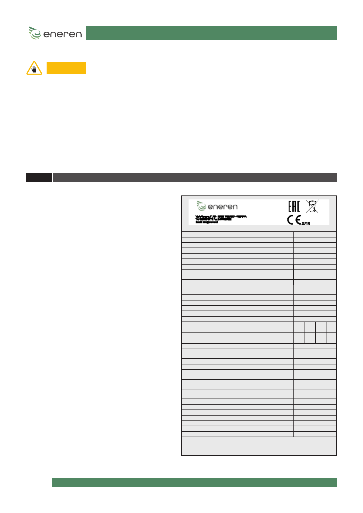
Each unit is distinguished by an identication label on the
frame, which bears all the data required for installation,
maintenance and unit traceability. Take note of the model,
serial number, the denitive refrigerant charge and the
reference drawings of the unit enclosed with this manual,
in order to be easily retrieved in the event the data plate
deteriorates and maintenance is required.
1.5 IDENTIFICATION OF THE UNIT
Modello - Model HHP0XXH
Matricola - Serial number HFXXXXXXXXXX
Codice ID - Code ID
Data di produzione - Date of production 22/08/17
Categoria PED/ 2014/68/EU Category II
Procedura di valutazione conformità - Conformity module D
Max pressione ammissibile PS - Max allowable pressure PS[bar-r] 41,5
"Max pressione esercizio lato bassa pressione PS
Max allowable pressure low pressure side PS [bar-r]"
41,5
Max/Min temp. di stoccaggio - Max-Min storage temperature [°C] +42 / -20
Max/Min.temp.amb. di funzionamento-Max/Min amb.working
temp.[°C]
+42 / -20
Potenza frigorifera* - Cooling Capacity* [ kW ]
EER*
Potenza termica* - Heating Capacity* [ kW ]
COP*
Refrigerante - Refrigerant [Ashrae 15/1992] / GWP R410A/2088
Carica refrigerante - Refrigerant charge [kg] C1 C2 C3 C4
(1*) - - -
Refrigerante aggiunto - Refrigerant added [kg] C1 C2 C3 C4
(2*) - - -
Carica totale - Total Charge [kg] (2*)
"Tonnellate di CO2 equivalenti
Tonnes of CO2 equivalent"
Taratura press. lato ALTA - HIGH pressure Switch Set [bar-r] 41,5
Taratura press. lato BASSA - LOW pressure Switch Set [bar-r] -
"Taratura valvola sicurezza refrigerante
Safety valve refrigerant Set [bar-r]"
-
"Massima pressione esercizio circuito acqua
Max working pressure water circuit [bar-r]"
5
"Taratura valvola sicurezza acqua
Safety valve water side Set [bar-r]"
-
Alimentazione Elettrica- Power supply 400V/3ph+N/50Hz
Potenza massima assorbita - Max. absorbed power [kW] 15,6
Corrente massima - Full load ampere FLA [A] 32
Corrente di spunto - Starting Current LRA [A] /
Schema elettrico - Wiring diagram HF620Axxxx
Schema frigorifero - Refrigeration diagram HF630Axxxx
Peso a vuoto - Empty weight [kg] 260
"* EN14511-2
Contiene gas uorurati ad eetto serra disciplinati dal protocollo di Kyoto
Contains uorinated greenhouse gases governed by the Kyoto protocol
Ermeticamente sigillato/Hermetically sealed"

11 -60
HHP - Reversible air-water heat pump
Installation, use and maintenance manual
HF61GJ0181C
1.6 GENERAL INSTRUCTIONS
- This manual must be stored carefully in a place that is known by the user of the unit,
managers and operators in charge of transport, installation, use, maintenance, repairs and
nal dismantling.
- This manual indicates the intended use of the unit and provides instructions regarding transport, installation,
assembly, adjustment and use. It provides information regarding maintenance, ordering spare parts, the presence
of residual risks and personnel training.
- It is important to remember that the use and maintenance manual can never replace adequate user experience.
This manual represents a reminder of the main operations to be performed by operators who have received
specic training, for example by attending training courses held by the manufacturer, with reference to particular
maintenance operations.
- This manual is to be considered an integral part of the unit and must be stored near the unit in a special container
until the unit is eventually demolished. Request a new copy from the manufacturer if it is lost or deteriorated.
- Make sure all the users have thoroughly understood the operating instructions together with the meaning of any
symbols on the unit.
- Potential accidents can be prevented by following these technical instructions with reference to Machinery
Directive 2006/42/EC and subsequent amendments.
- In any case, always comply with the national safety regulations.
- Do not remove or damage the safety devices, labels and notices, especially those imposed by law.
- Adhesive labels intended for safer use are applied to the unit, therefore, it is very important to replace them if they
become illegible.
- This manual reects the applicable technology at the time the unit is sold and cannot be considered inadequate
due to subsequent updates based on new experience.
- The MANUFACTURER has the right to update the production and manuals, without being obliged to update
previous production and manuals, except for exceptional cases.
- Please call on the telephone numbers found in this manual for any requests for updates of the use and maintenance
manual or supplements, which are to be considered an integral part of the manual.
- Contact THE MANUFACTURER for further information and to submit any proposals on how to improve the manual.
- THE MANUFACTURER kindly asks you to report the address of the new owner in case of transfer of the unit, in order
to facilitate forwarding any supplements of the manual to the new user.
WARNING

12 -60
HHP - Reversible air-water heat pump
Installation, use and maintenance manual
HF61GJ0181C
Every operator must use personal protective equipment such as gloves,
safety goggles and safety shoes.
Place a rst aid kit and a re extinguisher near the unit.
The extinguisher must always be fully loaded. Use it
according to the Standards in force.
Apply a "WORKS IN PROGRESS" sign on all sides of the unit.
Carefully check the unit according to the list of operations
specied in this manual.
The unit must only be used by qualied personnel, who is obliged to be aware of the lay-out and function of all the controls,
instruments, indicators, warning lights and various plates.
2 - SAFETY REQUIREMENTS
2.1 GENERAL SAFETY RULES
2.1.1 Thoroughly know the unit
2.1.2 Wear protective clothing
2.1.3 Use safety equipment
2.1.4 Maintenance and inspection warning signs
INSPECTION

13 -60
HHP - Reversible air-water heat pump
Installation, use and maintenance manual
HF61GJ0181C
The Machinery Directive 2006/42/EC provides the following denitions (attachment 1,1.1.1):
DANGER ZONE: any zone within and/or around machinery in which a person is subject to a risk to his health or
safety.
EXPOSED PERSON: any person wholly or partially in a danger zone.
OPERATOR: the person or persons installing, operating, adjusting, maintaining, cleaning, repairing or
moving machinery.
2.2 GENERAL PRECAUTIONS
- Itismandatorytoreadandcomplywith theinstructionsprovidedinthis useandmaintenance
manual before performing any operation or maintenance on the unit.
It is too late to do so while working: Persons may be seriously injured and property seriously damaged if operations
are performed incorrectly or the unit is not used as intended.
- The employer must provide all the operators with the details regarding the risk of accidents, especially those
deriving from noise, the personal protective equipment provided and the general accident prevention regulations
implemented by international laws or regulations or those applicable in the country of use.
All the operators must comply with international accident prevention regulations and those applicable in the
country of use in order to prevent potential accidents.
Please note that the European Union has issued certain Directives regarding health and safety of workers, among
which: Directive 89/391/EEC, 89/686/EEC, 89/654/EEC, 89/655/EEC, 89/656/EEC, 86/188/EEC, 92/58/EEC and 92/57/
EEC, which every employer is obliged to comply with and enforce.
- Before performing any work on the unit, each operator must be perfectly aware of how the unit and its controls
work and must have read and understood all the information in this manual.
WARNING
- It is strictly prohibited to remove or tamper with any safety device.
- All routine and special maintenance operations together with any installation must be
performed with the unit o and the power supply disconnected.
- Once the unit is cleaned, the operator must make sure there are no worn or damaged parts or other parts that are
not rmly attached; otherwise, a maintenance technician must be asked to intervene.
Particular attention must be paid to the integrity of the pressurised pipes or other components subject to wear.
Also make sure there are no leaking uids or hazardous substances.
Should there be any leak, the operator is prohibited from restarting the unit before having resolved the problem.
If such problems arise, the operator must ax a sign on the unit before abandoning it, thereby indicating that
maintenance is in progress and it is prohibited from starting it up.
- It is prohibited to use ammable uids to clean the unit.
- Periodically check the state of the labels and if necessary, replace them.
- The operator's workplace must be kept clean, tidy and free from objects that could hinder movements.
- The operators must not perform awkward operations, in uncomfortable positions, that could compromise their
balance.
The operators must pay attention to risks pertaining to clothing and/or being caught or entangled in moving parts.
It is recommended to use a cap to put up long hair.
- Chains, bracelets and rings can also pose a hazard.
- The workplace must be adequately lit up for the intended operations. Insucient or excessive lighting can pose
risks.
- The instructions, accident prevention regulations and warnings provided in this manual must always be complied
with.
WARNING
It is forbidden to tamper with or replace parts of the unit not expressly authorised by the
MANUFACTURER.
Using accessories, consumables or spare parts other than those recommended by the MANUFACTURER and/or
stipulated in this manual can constitute a risk for the operators and/or damage the unit.
Any alteration to the unit that is not specically authorised by the MANUFACTURER relieves the manufacturing
company from any civil or criminal liability.
WARNING

14 -60
HHP - Reversible air-water heat pump
Installation, use and maintenance manual
HF61GJ0181C
The units have been designed and built according to the current state-of-the-art and technical rules in force regarding
residential water-water heat pumps that exchange heat with the external ground. Applicable laws, provisions, regulations,
decrees and directives to such machinery have been complied with.
The materials used and the parts of equipment, as well as production procedures, quality and control assurance comply with
the highest standards of safety and reliability.
Unit performance, continuous operation and durability are maintained by using the above-mentioned materials and parts
for the purposes specied in this user manual, handling them with due care and performing thorough maintenance and
up-to-standard service.
The MANUFACTURER cannot be held liable for accidents caused when using the unit, due to the user not complying with
laws, provisions, regulations and standards in force regarding uid chillers and heat pumps.
THE MANUFACTURER cannot be held liable in case of malfunctions and damage if the unit:
- is used for purposes other than those intended;
- is not handled and maintained according to the operating rules specied in this manual;
- is not serviced regularly and continuously as prescribed or non-original spare parts are used;
- is either modied or a component is replaced without written authorisation from the MANUFACTURER, especially when
the eciency of the safety systems is intentionally reduced or eliminated;
- is used beyond the ambient temperature limits allowed.
2.2.1 Safety warnings
2.2.2 Accident prevention safety
2.2.3 Operational safety
Personal injury is prevented by not using worn or damaged, low quality or makeshift tools.
Routine maintenance specied in this manual must only be performed by authorised and trained personnel.
Contact the MANUFACTURER for maintenance or repairs not specied in this manual.
Stains of oil and grease and scattered tools or broken parts are hazardous as persons can slip or fall. Always keep the unit
area clean and tidy.
Do not use diesel or petroleum to clean the unit as they leave an oily layer that increases dust adhesion, and neither solvents
must be used (even if weak) as they damage the paint and increase the formation of rust.
If a jet of water penetrates the electrical equipment the contacts oxidise and the unit may malfunction.
Therefore, do not use jets of water or steam on the sensors, connectors or any electrical part.
2.3 PRECAUTIONS FOR MAINTENANCE
2.3.1 Tools
2.3.2 Personnel
2.3.3 Keeping the unit clean
WARNING The manufacturer cannot be held liable for damage caused if modied tools are used.

15 -60
HHP - Reversible air-water heat pump
Installation, use and maintenance manual
HF61GJ0181C
Many accidents and damage are due to maintenance errors, such as:
- lack of water in the circuit;
- incorrect percentage of refrigerant in the circuit;
- inadequate refrigerant;
- failure to keep the unit area clean;
- circuit ineciency (pipe connections, loose pipes, screws, etc.).
Maintenance must be performed carefully even for personal safety.
Never delay repairs.
Only specialised or authorised personnel must perform repairs.
Always comply with the following safety standards, even when you are completely familiar with all the operating elements:
- Always keep the unit and its surrounding area clean.
- Before starting work check that the safety devices are in perfect working condition.
- Make sure that no unqualied or unauthorised persons enter the unit area.
2.3.4 Care and maintenance
3 - DESCRIPTION OF THE PRODUCT AND TECHNICAL DATA
3.1 THE SERIES
3.1.1 Identication of the unit
HHP is a multi-purpose air-water heat pump that, by exchanging heat with the outside air, and with no combustion or ame,
warms, cools and produces domestic hot water in a fully autonomous way, as a priority.
During winter and autumn operation it heats the room or produces domestic hot water. The inertia of the system, increased
by the storage tank, which we recommend combining with the machine even on the heating system, also enables the
priority production of domestic hot water without discomfort.
During summer operation it cools the water for air conditioning purposes and, if necessary, dehumidies the rooms and
produces hot water as an alternative priority to cooling.
Here are the features shared by the units of the series:
• Split unit with compressor mounted in the indoor unit so as to reduce the emission of sound outdoors and to have
a lightweight outdoor unit that can be positioned at a height with simple brackets, or an outdoor unit running from
indoors, ductable, compact with reverse blade fans driven by a synchronous EC motor with permanent magnets.
• EEV (electronic expansion valve) to benet from the possibility of generating thermodynamic cycles with reduced
pressure surges and therefore signicant COP advantages.
• Integrated controller of the pump on the system circuit and DHW circuit: the pump is managed directly by the unit.
• AISI 316 stainless steel brazed high-eciency plate heat exchangers.
• Advanced electronic control to adequately address the needs of capacity control of loads for optimal operation of partial
loads, increasingly the subject of evaluation and discerning technical choices by heat engineering designers.
• Scroll or twin-rotary compressors, both with BLDC inverter
Dual hydraulic circuit:
• Air conditioning circuit with reversible cooling circuit side and variable set-point between min/max with potential-free
contact or with 0-10V or 4-20mA signal.
• DHW circuit managed with a 3-way valve installed inside the unit

16 -60
HHP - Reversible air-water heat pump
Installation, use and maintenance manual
HF61GJ0181C
The structure of the HHP series units has the following features:
• Indoor unit: side panelling in galvanised sheet metal painted with polyester epoxy powders and polymerised in the
oven at 180°C and a front cover with a built-in display. The unit is fully panelled, but can be accessed on 3 sides since the
panels can easily be removed, thus simplifying maintenance and/or inspections. All routine maintenance is performed
from the front of the machine.
• Outdoor unit: side panelling in galvanised sheet metal painted with polyester powders and polymerised in the oven
at 180°C. The unit is entirely faired, panelled and available in RAL9002. Axial 6-pole fans, with high degree coverage of
blades, combined with asynchronous motors with external rotor (or synchronous motors with permanent magnets) and
constant modulation of the rotation speed.
• Remote unit for indoor installation: panelling in galvanised sheet metal painted with polyester powders and polymerised
in the oven at 180°C. The unit is entirely faired and is available in RAL9002. Radial fans with brushless motors are used,
which are ideal for continuous and ecient modulation.
The components are distributed to guarantee easy access and the layout ensures optimum weight distribution on the unit’s
base.
17 -60
HHP - Reversible air-water heat pump
Installation, use and maintenance manual
HF61GJ0181C
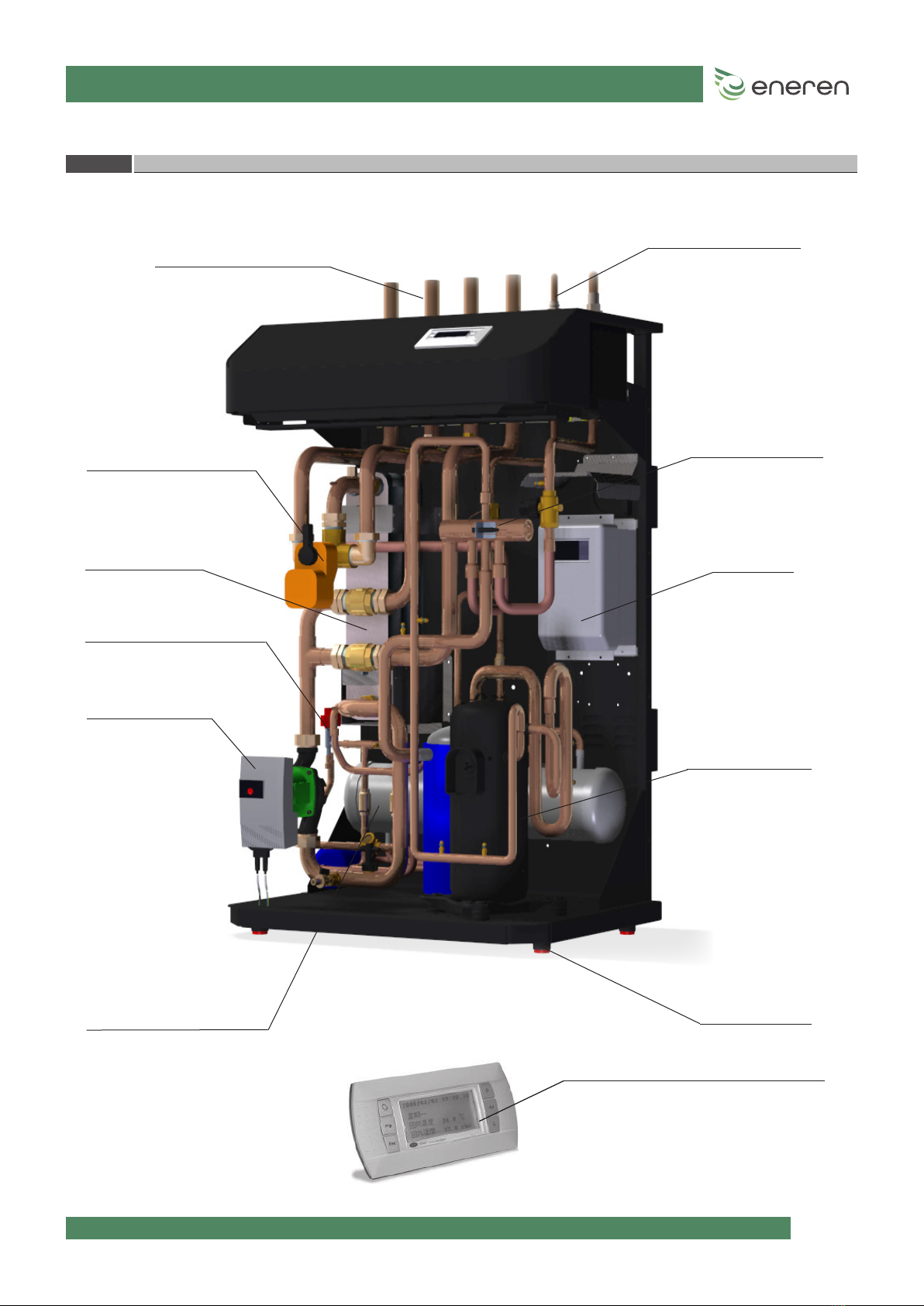
WATER CONNECTIONS
INVERTER
COMPRESSOR
PLATE HEAT
EXCHANGER
CIRCULATION
PUMP
EXPANSION VALVE
LIQUID RECEIVER VIBRATION DAMPERS
STANDARD USER INTERFACE
DIVERTER VALVE 4-WAY VALVE
3.1.2 Main components of the indoor unit
GAS CONNECTIONS

18 -60
HHP - Reversible air-water heat pump
Installation, use and maintenance manual
HF61GJ0181C
3.1.3 Main components of the outdoor unit
FINNED PACK HEAT
EXCHANGERS
FANS
GAS CONNECTIONS
The outdoor unit has the same components in all four sizes. The size of the nned coil changes together with the number of
fans that increase by one unit as the size increases (one fan for the 008, two for the 012, three for the 022 and four for the 033
and 044). The unit is available for horizontal operation (upwards air ow), vertical operation (horizontal air ow), or special
ducted operation for indoor installation.

19 -60
HHP - Reversible air-water heat pump
Installation, use and maintenance manual
HF61GJ0181C
3.1.4 Technical data
TECHNICAL DATA HHP008 HHP012 HHP022 HHP033 HHP044
Compressor operation [Hz] 30 80 30 110 30 75 30 120 30 120
MIN MAX MIN MAX MIN MAX MIN MAX MIN MAX
AIR COOLING 35/W7
Cooling Capacity [kW] 2.8 6.85 2.94 10.32 8.9 19.72 9.25 29.49 11.62 33.72
Cooling Capacity UNI EN 14511 [kW] 2.82 6.89 2.96 10.4 8.92 19.8 9.25 29.6 11.6 33.8
Compressor Power Input [kW] 0.63 1.99 0.61 3.04 2.12 6.02 2.06 10.73 2.49 14.26
Total Power Input [kW] 0.71 2.07 0.99 3.42 2.68 6.58 2.81 11.48 3.1 14.87
Tot Power Input UNI EN 14511 with pumps on
board [kW] 0.69 2.02 0.97 3.35 2.66 6.50 2.80 11.4 3.07 14.8
Total Input Current [A] 3.55 10.13 4.66 16.37 5.91 12.15 6.6 20.51 6.59 25.47
EER [-] 3.93 3.3 2.96 3.02 3.32 3.0 3.29 2.57 3.75 2.27
EER UNI EN 14511 [-] 4.09 3.41 3.05 3.10 3.35 3.05 3.30 2.60 3.78 2.28
UTILITY Water Flow Rate [kg/h] 480 1176 505 1773 1528 3386 1588 5064 1996 5790
AIR COOLING 35/W18
Cooling Capacity [kW] 3.95 9.5 4.16 14.45 12.45 27.23 13.01 40.82 16.39 45.67
Cooling Capacity UNI EN 14511 [kW] 3.98 9.55 4.20 14.5 12.5 27.3 13.0 40.9 16.5 45.7
Compressor Power Input [kW] 0.62 2.12 0.58 3.16 2.12 6.33 2.05 11.4 2.47 15.44
Total Power Input [kW] 0.7 2.2 0.96 3.54 2.68 6.89 2.8 12.15 3.08 16.04
Tot Power Input UNI EN 14511 with pumps on
board [kW] 0.67 2.15 0.93 3.49 2.64 6.83 2.76 12.1 3.02 16.0
Total Input Current [A] 3.49 10.73 4.51 16.98 5.91 12.65 6.59 21.58 6.56 27.36
EER [-] 5.65 4.32 4.32 4.08 4.64 3.95 4.64 3.36 5.32 2.85
EER UNI EN 14511 [-] 5.94 4.44 4.52 4.15 4.73 4.00 4.71 3.38 5.46 2.86
UTILITY Water Flow Rate [kg/h] 681 1639 718 2493 2147 4697 2243 7042 2828 7879
AIR HEATING 7/W35
Heating Capacity [kW] 3.11 8.3 3.18 12.49 10.09 23.65 10.26 37.32 12.42 43.55
Heating Capacity UNI EN 14511 [kW] 3.08 8.24 3.15 12.4 10.1 23.6 10.2 37.2 12.4 43.5
Compressor Power Input [kW] 0.58 1.7 0.58 2.67 1.95 5.18 1.91 9.0 2.28 11.24
Total Power Input [kW] 0.66 1.78 0.96 3.05 2.51 5.74 2.66 9.75 2.88 11.85
Tot Power Input UNI EN 14511 with pumps on
board [kW] 0.63 1.73 0.93 2.99 2.48 5.67 2.65 9.68 2.85 11.8
Total Input Current [A] 3.3 8.71 4.5 14.61 5.63 10.81 6.37 17.74 6.25 20.63
COP [-] 4.71 4.66 3.31 4.09 4.02 4.12 3.85 3.83 4.31 3.68
COP UNI EN 14511 [-] 4.89 4.76 3.39 4.15 4.07 4.16 3.85 3.84 4.35 3.69
UTILITY Water Flow Rate [kg/h] 539 1437 551 2163 1748 4096 1778 6463 2152 7544
DHW AIR 7/W55
Heating Capacity [kW] 2.8 7.57 2.8 11.53 9.27 22.4 9.37 35.8 10.98 40.39
Heating Capacity UNI EN 14511 [kW] 2.78 7.52 2.78 11.5 9.27 22.3 9.36 35.7 11.0 40.3
Compressor Power Input [kW] 0.88 2.53 0.89 4.0 2.9 7.63 2.88 13.37 3.46 16.88
Total Power Input [kW] 0.96 2.61 1.27 4.38 3.46 8.19 3.63 14.12 4.07 17.48
Tot Power Input UNI EN 14511 with pumps on
board [kW] 0.94 2.56 1.24 4.32 3.46 8.13 3.62 14.0 4.04 17.4
Total Input Current [A] 4.77 12.74 5.99 21.03 7.16 14.74 7.92 24.75 8.15 29.66
COP [-] 2.91 2.9 2.21 2.63 2.68 2.73 2.58 2.53 2.7 2.31
COP UNI EN 14511 [-] 2.96 2.94 2.24 2.66 2.68 2.74 2.59 2.55 2.72 2.32
UTILITY Water Flow Rate [kg/h] 489 1320 488 2012 1618 3907 1635 6245 1916 7046

20 -60
HHP - Reversible air-water heat pump
Installation, use and maintenance manual
HF61GJ0181C
TECHNICAL DATA HHP 008 HHP 012 HHP 022 HHP 033 HHP 044
Maximum electric absorption
Electrical power supply single-phase
230/1/50
single-phase
230/1/50
three-phase
400/3+N/50
three-phase
400/3+N/50
three-phase
400/3+N/50
Tot FLA [A] 19 21 20 32 50
Noise emission
Lw indoor unit noise power level [dBA] 53 54 55 57 58
Lp noise pressure (2m Q=2) ind. [dBA] 39 40 41 43 44
Lw outdoor unit noise power level [dBA] 62 65 66 69 69
Lp noise pressure (10m Q=2) out. [dBA] 34 37 38 41 41
Compressor
Type of compressor Twin Rotary Twin Rotary Scroll Scroll Scroll
Electric motor technology BLDC BLDC BLDC BLDC BLDC
N° compressors/cooling circuits 1/1 1/1 1/1 1/1 1/1
Dimensional drawing/Indoor unit frame F1 F1 F2 F2 F2
Dimensional drawing/Outdoor unit frame F1 F2 F3 F4 F4
Dimensions, weights and
connections
Indoor module dimensions (LxHxD) [mm] 802.5x1120.5x501.5 802.5x1120.5x501.5 804.5x1247x606 804.5x1247x606 804.5x1247x606
Outdoor module dimensions (LxHxD) [mm] 1120x881.5x515 1120x1230.5x515 1410x1278.5x515 2000x1511.5x540 2000x1511.5x540
Indoor module weight [kg] 190 190 260 270 305
Outdoor module weight [kg] 40 50 100 123 123
Energy class - ErP Directive
Energy class at 35°C - average climate A++ A+ A+ A+ A++
WARNING The data for the power supply values are meant as a guide. In any case refer to the unit’s
wiring diagram.
WARNING Dimensional drawings are meant as a guide. Please check the dimensional drawing enclosed
with the unit for an accurate reference.
This manual suits for next models
4
Table of contents
Other eneren Heat Pump manuals


Popular Heat Pump manuals by other brands

Omega
Omega VSHPe Series Installation and operation manual

Toshiba
Toshiba HWT-601F21SM3W-E installation manual

Panasonic
Panasonic Secon WH-MXC16J9E8 Service manual

Nibe
Nibe F1255 Series user manual

McQuay
McQuay Enfinity series Installation & maintenance data

Dimplex
Dimplex LA 17PS Installation and operating instructions


