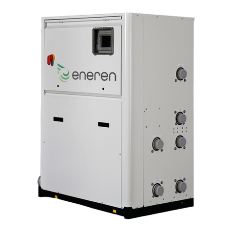
eneren CDH User manual

HF61GJ0475 / 02_20
USER MANUAL
CDH
EN
TRANSLATION OF THE ORIGINAL INSTRUCTIONS
HYDROTHERMAL AND
WATER/WATER GEOTHERMAL UNITS
WITH CO2 REFRIGERANT


INTRODUCTION
CDH
CWARNING
CAREFULLY READ THIS MANUAL BEFORE USING THE
UNIT.
CDECLARATION OF CONFORMITY
The declaration of conformity is attached separately to
the documents on board the unit, usually placed inside the
electrical compartment.
Dear Customer,
whilst thanking you for having chosen a product of ours, we are pleased to provide this manual for optimal use of our product
for better work results.
Please read the recommendations described in the following pages carefully and keep the manual available to personnel
who will be responsible for managing and maintaining the unit.
Our company is at your complete disposal for any and all questions that you should require both in the unit starting phase
and at any time of its utilization.
Should scheduled and unscheduled maintenance be necessary, please contact our After-sales Technical Service for assis-
tance and spare parts.
Please nd our contact details below for a more rapid service:
CDH |UsER MANUAL
3

START-UP INSTRUCTIONS
1 YOUR INSTALLATION
All the tips required for a perfect installation of the equip-
ment can be found in the installation manual.
It is important to place a net lter at all water circuit inlets.
The lter must be made of stainless steel with a mesh that
does not exceed 1 mm. See tables in section 5.3INFORMA-
TION ABOUT RECOMMENDED Y-SHAPED FILTERS p. 15
for the size.
2 REQUIRED ACCESSORIES FOR A PROPER INSTALLATION OF THE UNIT
For the proper operation of the unit and for the validity of the
warranty, the installation of the following hydraulic compo-
nents will be necessary:
ŪY-strainers in the inlet pipes to the unit;
Ūanti-vibration couplings in each pipe connected to the
unit;
Ūappropriately dimensioned safety valves on each circuit
of the system;
Ūappropriately dimensioned expansion vessels on each
circuit of the system.
3 FIRST START-UP
With at least 15 working days in advance, send the machine start request via email or fax to the following contact ENEREN:
Fax. 049 9588522
e-mail: [email protected]
Tel. 049 9271513
ENEREN Assistance will organize the intervention by putting you in contact with Authorized Technical Assistance Center of
the area.
All the preliminary checks and testing of the machine will be carried out together with your staff.
Your staff will be given instructions for the correct running of the machine.
4 WARRANTY ISSUE
For the warranty to be valid, the rst start-up by an Authorized Technical Assistance Center is mandatory
After testing, the Authorized Technical Assistance Center will issue a valid test certicate for the machine warranty.
5 CONNECTIONS
Here below are the minimum diameters for the pipes provid-
ing the connection to the units.
» Minimum diameter of the connection pipes for CDH units
CDH Unit of measurement
Minimum diameter of the connection pipes inches 1”
CDH |HF61GJ0475
4

TABLE OF CONTENTS
1 INTRODUCTION � � � � � � � � � � � � � � � � � � � � � � � �p.3
2 START-UP INSTRUCTIONS� � � � � � � � � � � � � � �p.4
3 GENERAL DESCRIPTION � � � � � � � � � � � � � � � �p.6
3.1 PRECAUTIONS FOR USE. . . . . . . . . . . . . . . . . . . . . . .p.6
3.2 INTRODUCTION. . . . . . . . . . . . . . . . . . . . . . . . . . . . . .p.6
3.3 LIABILITY. . . . . . . . . . . . . . . . . . . . . . . . . . . . . . . . . . .p.6
3.4 INTENDED USE . . . . . . . . . . . . . . . . . . . . . . . . . . . . . .p.7
3.5 IDENTIFICATION OFTHEUNIT . . . . . . . . . . . . . . . . .p.7
3.6 GENERAL INSTRUCTIONS . . . . . . . . . . . . . . . . . . . . .p.7
4 SAFETY PRESCRIPTIONS � � � � � � � � � � � � � � �p.9
4.1 GENERAL SAFETY RULES. . . . . . . . . . . . . . . . . . . . . .p.9
4.1.1 Thoroughly know the unit . . . . . . . . . . . . . . . . . . . . . . . .p.9
4.1.2 Wearprotectiveclothing . . . . . . . . . . . . . . . . . . . . . . . . .p.9
4.1.3 Usesafetyequipment . . . . . . . . . . . . . . . . . . . . . . . . . . .p.9
4.1.4 Warningsforinspectionsandmaintenance . . . . . . . . . . .p.9
4.2 GENERAL PRECAUTIONS . . . . . . . . . . . . . . . . . . . . . .p.9
4.2.1 Safetyinformation . . . . . . . . . . . . . . . . . . . . . . . . . . . .p.10
4.2.2 Accidentprevention . . . . . . . . . . . . . . . . . . . . . . . . . . .p.10
4.2.3 Operationalsafety . . . . . . . . . . . . . . . . . . . . . . . . . . . .p.10
4.3 MAINTENANCE PRECAUTIONS . . . . . . . . . . . . . . . .p.11
4.3.1 Tools . . . . . . . . . . . . . . . . . . . . . . . . . . . . . . . . . . . . . .p.11
4.3.2 Personnel. . . . . . . . . . . . . . . . . . . . . . . . . . . . . . . . . . .p.11
4.3.3 Keeptheunitclean. . . . . . . . . . . . . . . . . . . . . . . . . . . .p.11
4.3.4 Careandmaintenance . . . . . . . . . . . . . . . . . . . . . . . . .p.11
5 DESCRIPTION OF THE PRODUCT AND
TECHNICAL DATA � � � � � � � � � � � � � � � � � � � � �p.12
5.1 SERIES . . . . . . . . . . . . . . . . . . . . . . . . . . . . . . . . . . . .p.12
5.1.1 Identificationoftheunit . . . . . . . . . . . . . . . . . . . . . . . .p.13
5.1.2 Maincomponentsoftheindoorunit . . . . . . . . . . . . . . .p.13
5.1.3 Technicalspecifications . . . . . . . . . . . . . . . . . . . . . . . .p.14
5.2 OPERATING LIMITS. . . . . . . . . . . . . . . . . . . . . . . . . .p.14
5.2.1 Operatinglimits . . . . . . . . . . . . . . . . . . . . . . . . . . . . . .p.14
5.3 INFORMATION ABOUT RECOMMENDED
Y-SHAPEDFILTERS . . . . . . . . . . . . . . . . . . . . . . . . .p.15
5.4 CALIBRATION OF CONTROL DEVICES. . . . . . . . . . .p.16
5.4.1 Generaldescription . . . . . . . . . . . . . . . . . . . . . . . . . . .p.16
5.4.2 Maximumpressureswitch . . . . . . . . . . . . . . . . . . . . . .p.16
5.4.3 Servicethermostat . . . . . . . . . . . . . . . . . . . . . . . . . . . .p.16
5.4.4 Anti-freezethermostatfunction . . . . . . . . . . . . . . . . . .p.16
6 INSPECTION, TRANSPORT AND
POSITIONING � � � � � � � � � � � � � � � � � � � � � � � � �p.17
6.1 INSPECTION . . . . . . . . . . . . . . . . . . . . . . . . . . . . . . .p.17
6.2 LOCATION OF SAFETY DATA PLATES . . . . . . . . . . .p.17
6.2.1 Descriptionofthesafetylabels. . . . . . . . . . . . . . . . . . .p.18
6.2.2 Residualriskareas . . . . . . . . . . . . . . . . . . . . . . . . . . . .p.19
6.3 LIFTING AND TRANSPORT . . . . . . . . . . . . . . . . . . . .p.19
6.4 UNPACKING . . . . . . . . . . . . . . . . . . . . . . . . . . . . . . . .p.20
7 INSTALLATION � � � � � � � � � � � � � � � � � � � � � � � �p.21
7.1 POSITIONING AND INSTALLATION . . . . . . . . . . . . .p.21
7.2 QUALITYOFTHEWATERINTHESYSTEMS . . . . . .p.21
7.2.1 Water quality . . . . . . . . . . . . . . . . . . . . . . . . . . . . . . . .p.21
7.2.2 Waterqualityonaquiferside(ifthecircuitisopen) . . . .p.22
7.3 GENERAL RECOMMENDATION FOR WATER
CONNECTIONS . . . . . . . . . . . . . . . . . . . . . . . . . . . . .p.22
7.4 OPTIONAL STORAGE TANKS . . . . . . . . . . . . . . . . . .p.23
7.5 SAFETYDEVICESONTHEHIGHPRESSURESIDE
. . . . . . . . . . . . . . . . . . . . . . . . . . . . . . . . . . . . . . . . . .p.24
8 ELECTRICAL CONNECTIONS � � � � � � � � � � � �p.25
8.1 GENERAL INFORMATION . . . . . . . . . . . . . . . . . . . . .p.25
8.2 REMOTE CONTROLS . . . . . . . . . . . . . . . . . . . . . . . . .p.25
9 START-UP � � � � � � � � � � � � � � � � � � � � � � � � � � � �p.27
9.1 PRELIMINARYCHECKS . . . . . . . . . . . . . . . . . . . . . .p.27
9.2 STARTINGTHEUNIT. . . . . . . . . . . . . . . . . . . . . . . . .p.28
9.3 SELECTINGTHEOPERATINGMODES(IF
APPLICABLE). . . . . . . . . . . . . . . . . . . . . . . . . . . . . . .p.28
9.4 SETTINGTHESET-POINTS. . . . . . . . . . . . . . . . . . . .p.29
9.5 CHECKSDURINGOPERATION . . . . . . . . . . . . . . . . .p.30
9.6 STOPPINGTHEUNIT . . . . . . . . . . . . . . . . . . . . . . . .p.30
10 ROUTINE MAINTENANCE AND CHECKS � �p.31
10.1 REQUIREMENTS . . . . . . . . . . . . . . . . . . . . . . . . . . . .p.31
10.2 MAINTENANCE TABLE . . . . . . . . . . . . . . . . . . . . . . .p.31
10.3 REPAIRINGTHECOOLINGCIRCUIT. . . . . . . . . . . . .p.31
10.4 SEAL TEST . . . . . . . . . . . . . . . . . . . . . . . . . . . . . . . . .p.32
11 RETIRING THE UNIT � � � � � � � � � � � � � � � � � � �p.33
11.1 WASTE ELECTRICAL AND ELECTRONIC
EQUIPMENT MANAGEMENT. . . . . . . . . . . . . . . . . . .p.33
11.2 ENVIRONMENT PROTECTION . . . . . . . . . . . . . . . . .p.33
11.3 PACKAGING DISPOSAL. . . . . . . . . . . . . . . . . . . . . . .p.34
12 TROUBLESHOOTING � � � � � � � � � � � � � � � � � � �p.35
12.1 UNIT ALARM . . . . . . . . . . . . . . . . . . . . . . . . . . . . . . .p.35
12.2 TROUBLESHOOTING. . . . . . . . . . . . . . . . . . . . . . . . .p.35
13 SAFETY DATA SHEET OF REFRIGERANT
� � � � � � � � � � � � � � � � � � � � � � � � � � � � � � � � � � � � � �p.37
CDH |UsER MANUAL
5

3 GENERAL DESCRIPTION
3.1 PRECAUTIONS FOR USE
The operating rules contained in this manual are solely appli-
cable for the CDH units
The instructions manual must be read and used as follows:
Ūevery unit operator and maintenance technician must
carefully read the entire manual and comply with that
stipulated therein;
Ūthe employer must ensure that the operator has the re-
quirements to operate the unit and has carefully read the
manual;
Ūread the instructions manual carefully and consider it an
integral part of the unit;
Ūthe instructions manual must be readily available to op-
erating personnel and maintenance technicians;
Ūkeep the manual throughout the life of the unit;
Ūmake sure that any update is included in the text;
Ūhand the manual to any other user or subsequent owner
of the unit;
Ūuse the manual in such a way so as not to damage its
content;
Ūdo not, for any reason, remove, tear or rewrite parts of
the manual;
Ūkeep the manual away from humidity and heat;
Ūif the manual is lost or partially damaged and therefore
the contents can no longer be read entirely, it is advisa-
ble to request a new manual from the manufacturer by
communicating the code found on the cover or the serial
number of the unit.
Pay utmost attention to the following symbols and their
meaning. Their purpose is to highlight specic information
such as:
CWARNING: With reference to additional infor-
mation or suggestions for the unit to be used
correctly.
ADANGER: With reference to dangerous situ-
ations that could arise while using the unit, in
order to guarantee personal safety.
BWARNING: With reference to dangerous sit-
uations that could arise while using the unit, in
order to prevent damaging objects and the unit
itself.
3.2 INTRODUCTION
The operating rules described in this manual are an integral
part of the unit supply.
These rules are also intended for the previously trained op-
erator specically to operate this type of unit and contain all
the necessary and important information for operating safe-
ty and optimal, proper use of the unit.
Hurried and incomplete training leads to improvisation,
which is the cause of many accidents.
Before starting to work, read through and strictly observe the
following suggestions:
Ūthe operator must always have the instructions manual
at his disposal;
Ūplan each action carefully;
Ūbefore starting work, make sure the safety devices func-
tion correctly and you have no doubts on how they work;
otherwise, do not start-up the unit;
Ūcarefully observe the warnings relating to special haz-
ards contained in this manual;
Ūpreventive and thorough maintenance guarantees con-
stantly high operating safety for the unit. Never delay
repairs and always have them carried out solely by qual-
ied personnel; only original spare parts are to be used.
3.3 LIABILITY
The MANUFACTURER cannot be held liable for any personal
accident or damage to property, which may arise from:
Ūfailure to comply with the instructions provided in this
manual regarding unit management, use and mainte-
nance;
Ūviolent actions or incorrect manoeuvres when perform-
ing maintenance on the unit;
Ūalterations made to the unit without prior written author-
isation from the MANUFACTURER;
Ūincidents beyond the normal and correct use of the unit.
In any case, if the user attributes the incident to a defect in
the unit, he must prove that the damage caused was a main
and direct consequence of this “defect”.
BATTENTION
ŪWhen installing or servicing the unit, the rules stipulat-
ed in this manual must be complied with together with
those on board the unit and in any case all necessary
precautions must be taken.
ŪThe presence of pressurised uids in the refrigerant cir-
cuit and of electrical components can create hazardous
situations during installation and maintenance.
ŪTherefore, only qualied personnel may perform work on
the unit.
ŪTHE UNIT MUST BE STARTED UP FOR THE FIRST TIME
ONLY BY QUALIFIED PERSONNEL AUTHORISED BY THE
COMPANY PLACING IT ON THE MARKET.
ŪFAILURE TO COMPLY WITH THE RULES STIPULATED
IN THIS MANUAL AND ANY ALTERATION TO THE UNIT
WITHOUT PRIOR AUTHORISATION WILL IMMEDIATELY
MAKE THE WARRANTY NULL AND VOID.
ŪBefore performing any work on the unit, ensure it has
been disconnected from the power supply.
ŪFor maintenance service or repairs always and exclu-
sively use original spare parts. THE MANUFACTURER de-
clines all responsibility for damages that may occur due
to non-compliance with the above.
ŪThe unit is covered by the warranty according to the con-
tractual agreements established at the time of sale.
CDH |HF61GJ0475
6

ŪHowever, the warranty is rendered null and void if the reg-
ulations and user instructions stipulated in this manual
are not complied with.
ŪIn the event of a fault, do not try to repair it yourself or
have an unauthorised technician perform the repairs.
The warranty will otherwise be rendered null and void.
3.4 INTENDED USE
The CDH units are water-water heat pumps that, with no
combustion or ame, warm or cool the whole house and
autonomously produce technical hot water for domestic
purposes, thanks to the heat exchanged with the ground out-
side.
Their use is recommended within the functioning limits car-
ried in this manual, or else the warranty attached to the sales
contract would cease.
Any other use is to be considered inappropriate and the
manufacturer declines all liability for any damage caused to
persons, property or the unit that may derive from such use.
ADANGER
ŪPlace the unit in environments where there is no risk of
explosion, corrosion or re.
ŪR744 refrigerant is a non-toxic gas, but suffocating.
Ensure adequate ventilation to the installation room to
protect against any refrigerant leaks. In case of instal-
lation in a closed environment, it is required to install a
refrigerant leak detector which, in case of alarm, should
turn off the unit to avoid the risk of asphyxia. Also, the
circuit safety valve must be conveyed to an outside en-
vironment.
ŪImproper use could cause serious repercussions on the
unit.
ŪAll routine and special maintenance operations must be
performed with the unit off and the power supply discon-
nected.
BATTENTION
ŪBefore performing any work on the unit, each operator
must be perfectly aware of how the unit and its controls
work and must have read and understood all the techni-
cal information in this manual.
ŪIt is forbidden to use the unit in conditions or for purpos-
es other than those stipulated in this manual and THE
MANUFACTURER cannot be liable for faults, issues or
accidents due to non-compliance with this prohibition.
ŪDo not repair high pressure pipes with welds.
ŪIt is forbidden to tamper with, alter or modify, even par-
tially, the systems or equipment described in the instruc-
tion manual, and in particular, the guards and warning
symbols required for personal safety.
ŪIt is also forbidden to operate in manners different from
those indicated or fail to perform operations necessary
for safety reasons.
ŪSafety instructions are particularly important, as well as
general information contained in this manual.
3.5 IDENTIFICATION OF THE
UNIT
Each unit is distinguished by an identication label on the
frame, which bears all the data required for installation,
maintenance and unit traceability. Take note of the model,
serial number, the denitive refrigerant charge and the refer-
ence drawings of the unit enclosed with this manual, in order
to be easily retrieved in the event the data plate deteriorates
and maintenance is required.
»
Manufatured byHiRef S.p.A.
Via Spagna,31-33 Z.I.-35020 Tribano(PD)-Italy Tel.+390499588511-Fax+390499588522
P.I.e C.F. 04226420281
2761
Modello - Model
Matricola - Serial Number
Codice ID - Code ID
Data di Produzione - Date of production
Categoria PED/2014/68/EU Category
Modulo di valutazione - Conformity Module
Max pressione ammissibile
Max allowed pressure PS [bar-r]
Max pressione ammissibile lato bassa
Max allowed pressure low side PS [bar-r]
Max/Min temp. stoccaggio - Max/Min storage temp
Potenza frigorifera - Cooling capacity*
EER*
Potenza termica - Heating capacity*
COP*
Refrigerante - Refrigerant [Ashrae 15/1992]/GWP
Carica refrigerante - Refrigerant charge [kg]
Refrigerante aggiunto - Refrigerant added [kg]
Carica totale - Total Charge [kg]
Ton. di CO2 equivalenti-Tonnes of CO2 equivalent
Tar press. lato ALTA-HIGH pressure Switch Set [bar-r]
Tar press. lato BASSA-LOW pressure Switch Set [bar-r]
Taratura valvola sicurezza refrigerante
Safety valve refrigerant Set [bar-r]
Taratura valvola sicurezza acqua
Safety valve water side Set [bar-r]
Alim. elettrica principale-Main Power supply
Alim. elettrica secondaria-Secondary Power supply
Potenza massima assorbita - Max. absorbed power [kW]
Corrente massima - Full load ampere FLA [A]
Corrente di spunto - Starting Current LRA [A]
Schema elettrico - Wiring diagram
Schema frigorifero - Refrigeration diagram
Peso a vuoto - Empty weight [kg]
* EN14511-2
Contains fluorinated greenhouse gases
3.6 GENERAL INSTRUCTIONS
BATTENTION
ŪThis manual must be stored carefully in a place that is
known by the user of the unit, managers and operators
in charge of transport, installation, use, maintenance, re-
pairs and nal dismantling.
ŪThis manual indicates the intended use of the unit and
provides instructions regarding transport, installation,
assembly, adjustment and use. It provides information
regarding maintenance, ordering spare parts, the pres-
ence of residual risks and personnel training.
ŪIt is important to remember that the use and mainte-
nance manual can never replace adequate user experi-
ence. This manual represents a reminder of the main op-
erations to be performed by operators who have received
CDH |UsER MANUAL
7

specic training, for example by attending training cours-
es held by the manufacturer, with reference to particular
maintenance operations.
ŪThis manual is to be considered an integral part of the
unit and must be stored near the unit in a special contain-
er until the unit is eventually demolished. Request a new
copy from the manufacturer if it is lost or deteriorated.
ŪMake sure all the users have thoroughly understood the
operating instructions together with the meaning of any
symbols on the unit.
ŪPossible accidents can be avoided by following these
technical instructions drafted in accordance with the Ma-
chinery Directive 2006/42/EC and subsequent additions.
ŪIn any case, always comply with national safety regula-
tions.
ŪDo not remove or damage the safety devices, labels and
notices, especially those imposed by law.
ŪAdhesive labels intended for safer use are applied to the
unit, therefore, it is very important to replace them if they
become illegible.
ŪThis manual reects the applicable technology at the
time the unit is sold and cannot be considered inade-
quate due to subsequent updates based on new expe-
rience.
ŪThe MANUFACTURER has the right to update the pro-
duction and manuals, without being obliged to update
previous production and manuals, except for exceptional
cases.
ŪAny updates or additions to this use and maintenance
manual are to be considered an integral part of the man-
ual and may be requested via the contact phone num-
bers listed in this manual.
ŪContact THE MANUFACTURER for further information
and to submit any proposals on how to improve the man-
ual.
ŪTHE MANUFACTURER kindly asks you to report the ad-
dress of the new owner in case of transfer of the unit,
in order to facilitate forwarding any supplements of the
manual to the new user.
CDH |HF61GJ0475
8

4 SAFETY PRESCRIPTIONS
4.1 GENERAL SAFETY RULES
4.1.1 Thoroughly know the unit
The unit must only be used by qualied personnel, who is
obliged to be aware of the lay-out and function of all the
controls, instruments, indicators, warning lights and various
plates.
4.1.2 Wear protective clothing
Every operator must use personal protective equipment
such as gloves, safety goggles and safety shoes.
OS
OS
4.1.3 Use safety equipment
A rst aid kit and a re extinguisher must be placed near the
unit.
The extinguisher must always be fully loaded. Use it accord-
ing to the Standards in force.
OS
4.1.4 Warnings for inspections and
maintenance
Display a sign with the warning: “INSPECTION IN PRO-
GRESS” on all sides of the unit.
Check the unit carefully following the list of operations con-
tained in this manual.
INSPECTION
IN PROGRESS
4.2 GENERAL PRECAUTIONS
The Machinery Directive 2006/42/EC provides the following
denitions (attachment 1,1.1.1):
DANGER ZONE: any zone within and/or around machinery
in which a person is subject to a risk to his health or safety.
EXPOSED PERSON: any person wholly or partially in a dan-
ger zone.
OPERATOR: the person or persons installing, operating, ad-
justing, maintaining, cleaning, repairing or moving machin-
ery.
CWARNING
ŪIt is mandatory to read and comply with the instructions
provided in this use and maintenance manual before per-
forming any operation or maintenance on the unit. It is
too late to do so while working: Persons may be seriously
injured and property seriously damaged if operations are
performed incorrectly or the unit is not used as intended.
ŪThe employer must inform in detail all operators about
the risks of accidents and particularly about risks related
to noise, required personal protective devices and gener-
al accident prevention rules provided by laws or interna-
tional standards and national standards in the Country of
destination of the unit.
CDH |UsER MANUAL
9

ŪAll the operators must comply with international acci-
dent prevention regulations and those applicable in the
country of use in order to prevent potential accidents.
ŪPlease be reminded that the European Union has is-
sued some directives concerning the safety and health
of workers, among which the directives 89/391/EEC,
89/686/EEC, 89/654/EEC, 2009/104/EC, 89/656/EEC,
2003/10/EC, 92/58/EEC and 92/57/EEC that each em-
ployer has an obligation to observe and to enforce. In the
event that the unit is installed outside the European un-
ion, always refer to the regulations in force in the country
of installation.
ŪBefore performing any work on the unit, each operator
must be perfectly aware of how the unit and its controls
work and must have read and understood all the techni-
cal information in this manual.
BATTENTION
It is forbidden to tamper with or replace parts of the unit not
expressly authorised by the MANUFACTURER.
Using accessories, consumables or spare parts other than
those recommended by the MANUFACTURER and/or stipu-
lated in this manual can constitute a risk for the operators
and/or damage the unit.
Any alteration to the unit that is not specically authorised
by the MANUFACTURER relieves the manufacturing compa-
ny from any civil or criminal liability.
CWARNING
ŪIt is strictly prohibited to remove or tamper with any safe-
ty device.
ŪAny installation, ordinary and extraordinary maintenance
operations must be carried out with the unit stopped and
without power supply.
ŪOnce the unit has been cleaned, the operator must check
that there are no worn or damaged parts or parts that
are not safely xed, or if this is the case, ask the mainte-
nance staff to x the problem.
ŪSpecial attention must be paid to the state of repair of
the pressurised pipes or other parts exposed to wear. It
must also be ensured that there are no leaks of uid, or
other dangerous substances.
ŪIn these cases, it is forbidden for the operator to restart
the unit before the situation has been remedied.
ŪIf any of these occurrences are detected, the operator,
before leaving the unit unattended, must display a warn-
ing sign indicating that maintenance is in progress and it
is forbidden to start the unit.
ŪIt is prohibited to use ammable uids to clean the unit.
ŪPeriodically check the condition of the data plates and
arrange, if necessary, for them to be restored.
ŪThe operator work place must be kept clean, tidy and free
from any objects that may limit unhindered movement.
ŪOperators should avoid operating the device from unsafe,
uncomfortable positions that may affect their balance.
ŪThe operators must pay attention to risks pertaining to
clothing and/or being caught or entangled in moving
parts. It is recommended to use a cap to put up long hair.
ŪChains, bracelets and rings can also pose a hazard.
ŪThe workplace must be adequately lit for the intended
operations. Insucient or excessively bright lighting can
imply safety risks.
ŪEnsure adequate ventilation to the installation room to
protect against any refrigerant leaks.
ŪThe instructions, accident-prevention rules and warnings
contained in this manual must be observed at all times.
ADANGER
R744 refrigerant is a non-toxic gas, but suffocating. In case
of installation in a closed environment, it is required to install
a refrigerant leak detector which, in case of alarm, should
turn off the unit to avoid the risk of asphyxia. Also, the circuit
safety valve must be conveyed to an outside environment.
Also follow the guidelines for CO2 emissions prevention in
section 9.5CHECKS DURING OPERATIONp.30.
ADANGER
By using R744 refrigerant, the chiller works at high pressure
and temperature levels, considerably higher than in a normal
refrigeration / conditioning cycle.
We therefore recommend an even higher level of attention
and scruple than the usual start-up, speed and maintenance
operations and above all to carry out the latter only with the
unit off.
Maintenance and panels removal must only be carried out
when the unit is OFF. This will prevent scalding hazards and
explosion-related hazards due to the presence of pressur-
ised circuits.
4.2.1 Safety information
The units have been designed and built according to the cur-
rent state-of-the-art and technical rules in force regarding
residential water-water heat pumps that exchange heat with
the external ground. Applicable laws, provisions, regulations,
decrees and directives to such machinery have been com-
plied with.
The materials and the equipment parts used, as well as the
production, quality assurance and control processes meet
the highest safety and reliability requirements.
Unit performance, continuous operation and durability are
maintained by using the above-mentioned materials and
parts for the purposes specied in this user manual, han-
dling them with due care and performing thorough mainte-
nance and up-to-standard service.
4.2.2 Accident prevention
The MANUFACTURER cannot be held liable for accidents
caused when using the unit, due to the user not complying
with laws, provisions, regulations and standards in force re-
garding uid chillers and heat pumps.
4.2.3 Operational safety
The MANUFACTURER will not be responsible in case of mal-
functions and damage if the unit:
Ūis used for purposes other than those intended;
ŪIs not handled and maintained according to the operat-
ing rules specied in this manual;
ŪIt does not regularly and consistently receive mainte-
nance as prescribed or non-original spare parts are used;
ŪIs modied or some components are replaced without
the MANUFACTURER’s written authorisation, especially
CDH |HF61GJ0475
10

when the effectiveness of the safety systems has been
altered or minimised on purpose;
ŪIs used beyond the ambient temperature limits allowed.
4.3 MAINTENANCE
PRECAUTIONS
4.3.1 Tools
Personal injury is prevented by not using worn or damaged,
low quality or makeshift tools.
BATTENTION
The manufacturer cannot be held liable for damage caused
if modied tools are used.
4.3.2 Personnel
Ordinary maintenance prescribed in this manual must only
be performed by authorised and trained personnel. For the
maintenance or overhauling of components not specied in
this manual, contact the MANUFACTURER.
4.3.3 Keep the unit clean
Oil and grease stains, misplaced tools or broken pieces are
harmful to people as they can cause slipping or falls. Always
keep the area where the unit is installed clean and tidy.
Do not use diesel fuel, oil or solvents to clean the unit as the
rst two leave an oily lm that makes it easier for dust to
stick, while solvents (even milder ones) damage the paint
nish and cause rusting.
If a jet of water penetrates the electrical equipment the con-
tacts oxidise and the unit may malfunction. Therefore, do
not use jets of water or steam on the sensors, connectors or
any electrical part.
4.3.4 Care and maintenance
The cause of damages and accidents is often attributable to
wrong maintenance, such as:
ŪNo water in the circuit;
ŪIncorrect percentage of refrigerant in the circuit;
ŪInadequate refrigerant;
ŪPoor cleaning in the unit setting;
ŪCircuit ineciency (pipe connections, loose pipes,
screws, etc.).
Carry out maintenance work as required: this is also critical
for your own safety.
Never postpone scheduled repairs.
Only assign skilled or authorised personnel to repair tasks.
Always observe the following safety rules, even when you
are thoroughly familiar with the operations involved:
ŪAlways keep the unit and the surrounding area clean;
ŪBefore beginning to work, check the perfect eciency of
protective devices;
ŪMake sure that no unqualied or not specially appointed
persons enter the unit operating area.
CDH |UsER MANUAL
11

5 DESCRIPTION OF THE PRODUCT AND TECHNICAL DATA
5.1 SERIES
The CDH units described in this manual are heat pumps for
the production of domestic hot water and/or heating of the
living spaces.
During autumn and winter operation, they heat the room or
produce domestic hot water.
1) Production of domestic hot water only.
2) These units have one reversible hot hydraulic side and another one dedicated to the domestic hot water production.
CDH |HF61GJ0475
12

BATTENTION
The system diagrams shown in this manual are generic and
illustrative. For proper installation guidelines, please follow
the dimensional and wiring diagrams supplied with the unit.
BATTENTION
For proper installation guidelines, please follow the dimen-
sional and wiring diagrams supplied with the unit.
5.1.1 Identification of the unit
Here are the features shared by the units of the series:
ŪExpansion device: EEV (electronic expansion valve) to
benet from the possibility of generating thermodynam-
ic cycles with reduced pressure changes and therefore
signicant COP advantages.
ŪIntegrated controller of the pump on the system circuit
and DHW circuit: the pump is managed directly by the
unit.
ŪDissipation circuit pump with variable speed combined
with an inverter.
ŪAISI 316 Stainless steel high-eciency plate heat ex-
changers.
ŪAdvanced electronic control to adequately address the
needs of capacity control of loads for optimal operation
of partial loads, increasingly the subject of evaluation
and discerning technical choices by heat engineering
designers.
The basic selection in the development of the series con-
sists in using the following:
ŪReciprocating or twin-rotary compressors, on/off units
or inverters
The structure of the internal unit features the following char-
acteristics: side panelling in galvanised sheet metal painted
with polyester epoxy powders and polymerised in the oven
at 180°C and a front cover with a built-in display. The unit
is fully panelled, but can be accessed on 3 sides since the
panels can easily be removed, thus simplifying maintenance
and/or inspections. All routine maintenance is performed
from the front of the unit.
5.1.2 Main components of the indoor unit
1 Water connections
2 Circulation pumps
3 Compressor
4 Liquid separator
5 Regenerator
6 Safety valves
7 Expansion valves
8 Plate exchanger
9 Compressor box
10 Standard user interface
11 Electrical panel
03
06
02
11
01
08
07
05
04
10
FRONT OF THE UNIT REAR OF THE UNIT
01
05
08
08
11
04
07
03
07
06
CDH |UsER MANUAL
13

5.1.3 Technical specifications
CWARNING
For unit dimensions and technical data, please follow the
dimensional drawings and the specic technical selection
supplied with the unit.
5.2 OPERATING LIMITS
The diagrams below indicate the operating limits of the
units. One can obtain the ow temperature that the unit can
supply according to the temperature of the water coming in
from the source.
CWARNING
All the temperatures on the perimeter of the operating areas
can only be reached as transients and if the unit runs beyond
these limits for a prolonged time, the software on board will
implement corrective actions to restore the unit within the
operating limits.
Heat transfer uid: water or mixture of water and max 30% glycol antifreeze
Maximum water side pressure: 5 bar
Maximum pressure on high pressure side: 125 bar-r
Maximum ambient Temp of the unit: +50 °C
Minimum ambient Temp of the unit: -15 °C
Maximum pressure on low pressure side: 90 bar-r (*)
Power supply voltage: +/- 10% compared to plate voltage
Maximum storage Temp of the unit: +60 °C
Minimum storage Temp of the unit: -20 °C (limit determined by on board electronics)
(*)thisvaluecanonlybereachedduringstorageanddeterminesthesaturationpressureof30bar-roftherefrigerantonthelowpressuresideofthecircuit(valuewhich
determinesitslimits).
BATTENTION
Using glycol is necessary in all cases in which the tempera-
ture of the heat transfer uid drops below 0°C, i.e. even when
the unit is switched off or only running in summer mode,
should this temperature condition occur. This will prevent
water freezing and the resulting internal damage to compo-
nents.
The percentage of glycol must be selected according to the
lowest expected temperature.
Glycol percentage by weight %0% 10% 15% 20% 25% 30% 40% 50%
Freezing temperature of the mixture with ethylene
glycol °C 0-3 -5 -8 -11 -14 -22 -34
Freezing temperature of the mixture with propylene
glycol °C 0-3 -5 -7 -10 -13 -21 -33
The use of glycol will change the thermal capacity, the
water ow and the pressure drops. The corrective factors
depending on the amount of glycol present in the mixture are
shown in the following table.
Glycolpercentagebyweight 0% 10% 20% 30% 40%
ETHYLENE-BASED
Developed heat capacity correction factor 10,998 0,994 0,989 0,983
Water ow correction factor 11,047 1,094 1,14 1,199
Pressure drop correction factor 11,157 1,352 1,585 1,86
PROPYLENE-BASED
Developed heat capacity correction factor 10,996 0,985 0,971 0,96
Water ow correction factor 11,022 1,043 1,07 1,098
Pressure drop correction factor 11,111 1,307 1,532 1,777
5.2.1 Operating limits
Operating limits for user water and source circuit tempera-
ture:
CDH |HF61GJ0475
14

-20 -10 0 10 20 30
Uscita
Ingresso
Temperatura uscita sorgente [°C]
Temperatura Utenza [°C]
Limiti operativi
100
90
80
70
60
50
40
30
20
10
0
CWARNING
The unit must operate within the above values. If not:
ŪThe compressor may be subject to malfunction until
breaking.
ŪThe warranty will be invalidated.
5.3 INFORMATION ABOUT
RECOMMENDED
Y-SHAPED FILTERS
The following tables report the technical specications of
Y-shaped lters to be installed at the heat pump’s inlet.
CWARNING
Always follow the indications on the minimum diameter of
the connecting piping reported in the table.
ŪBronze body
ŪSN 5 UNI-EN1982 DIN 50930/6
ŪBronze cap CW 617 N - UNI-EN12165
ŪBody gasket BETAFLEX 71
ŪSandblasted nish
ŪThread EN-ISO 228/1
ŪAISI 304 stainless steel rhomboid micro-stretched sheet
metal lter
CDH Size 020
Flow rate under nominal conditions kg/h 5600
Filtering degree μ500
kv m3/h 24.5
Filter pressure drops kPa 6
Minimum lter diameter required inches 1”1/2
CDH |UsER MANUAL
15

5.4 CALIBRATION OF
CONTROL DEVICES
5.4.1 General description
All the control devices are set and tested in the factory be-
fore the unit is dispatched. However, after the unit has been
in service for a reasonable period of time you can perform a
check on the operating and safety devices. The settings are
shown in Tables I and II.
ADANGER
All service operations on the control equipment must be car-
ried out EXCLUSIVELY BY QUALIFIED PERSONNEL: incorrect
calibration valuescan cause serious personal injuries and
damage the unit.
Many of the operating parameters and system settings are
congured by means of the microprocessor control and are
protected by passwords.
TableI–Settingofcontroldevices
Control device Setpoint Differential
Hot user set °C 75 4
TableII–Settingofsafety-controldevices
Control device Startup Differential Re-activation
Anti-freeze thermostat - °C +4 1Semi-automatic
High pressure set by probe - bar 120 5Semi-automatic
Maximum pressure safety switch - bar 125 15-30 Automatic
Safety valve - bar 130 - -
Minimum time lapse between two compressor’s start-ups - s 450 - -
Flow switch alarm delay - s 15 (start-up) 5 (running) -
Low pressure alarm delay - s 0 -
5.4.2 Maximum pressure switch
The high pressure switch is of the automatically reset type
and classiable as category IV under 97/23 EC. It directly
stops the compressor when the discharge pressure exceeds
the set value.
BATTENTION
Any kind of block or alarm must be promptly reported to the
After Sales Service!
The high pressure switch must be automatically reset; this is
possible only when the pressure falls below the set differen-
tial (see Table II).
5.4.3 Service thermostat
This function starts and stops the compressors according
to the demand for chilled water, as determined by a sensor
placed at the evaporator inlet [water returning from the sys-
tem].
This device is a function included in the microprocessor con-
trol and works with a proportional band width that may be
set as desired.
5.4.4 Anti-freeze thermostat function
The anti-freeze sensor situated at the evaporator outlet
detects the presence of excessively low temperatures and
stops the unit. Together with the ow switch and low pres-
sure switch, this device protects the evaporator from the risk
of freezing as a result of faults in the water circuit.
This device is a function included in the microprocessor con-
trol.
BATTENTION
If there are any alarms relating to the intervention of the pro-
tections described, the unit must request the intervention of
the Authorised Technical Service Centre, otherwise the war-
ranty will be considered null and void.
CDH |HF61GJ0475
16

6 INSPECTION, TRANSPORT AND POSITIONING
6.1 INSPECTION
The unit left the factory in perfect conditions, however when
receiving the unit verify its integrity. Immediately report any
damage to the carrier and write it down on the Delivery Note
before signing it.
The manufacturer or its agent must be promptly notied of
the extent of the damage.
The Customer must submit a written report describing any
signicant damage.
Check the integrity of the documents accompanying the unit
and of this manual.
Check for the presence of the wiring diagram.
After starting up the unit, check the commissioning report.
6.2 LOCATION OF SAFETY DATA PLATES
3a 01
3b
04
02
CDH |UsER MANUAL
17

3a 01
3b
04
02
6.2.1 Description of the safety labels
1
A. Warning: danger due to poor familiarity with all the functions of the unit and the
resulting risks.
B. Read the use and maintenance manual carefully before operating the unit.
A B
2
Electric power supply data plate +
3
A. Danger: live parts.
B. Danger of burns.
AB
4
Liquid refrigerant.
CDH |HF61GJ0475
18

6.2.2 Residual risk areas
ADANGER
It has not been possible to eliminate certain residual risks
during the design phase, found in some areas of the unit, or
protected with guards due to specic features of the unit.
Each operator must be aware of the residual risks on this
unit in order to prevent potential accidents.
CWARNING
In order to avoid the risks listed above it is essentially im-
portant to:
ŪUse the electric panel in compliance with the manufac-
turer’s instructions. Do not place metal objects inside the
electric panel. Do not place ammable substances near
the unit.
ŪDo not alter any component of the cooling circuit and do
not operate the unit beyond the limits stipulated by the
manufacturer.
ŪDispose of all the materials that make up the machine
correctly, use suitable equipment for the recovery of the
refrigerant gas (see chapter [Ref][Ref]).
ŪNot touch the internal components during operation
without adequate protection.
» Residual risk areas
a-Riskofshortcircuitandre.
b-Riskofexplosionduetothepresenceofhighpressurecircuits.
c-Riskofpollutionduetothepresenceofoil.
d-Riskofburnsduetothepresenceofveryhotsurfaces.
a
c
a
b
d
a
c
ADANGER
By using R744 refrigerant, the chiller works at high pressure
and temperature levels, considerably higher than in a normal
refrigeration / conditioning cycle.
We therefore recommend an even higher level of attention
and scruple than the usual start-up, speed and maintenance
operations and above all to carry out the latter only with the
unit off.
Maintenance and panels removal must only be carried out
when the unit is OFF.
This will prevent scalding hazards and explosion-related
hazards due to the presence of pressurised circuits.
6.3 LIFTING AND
TRANSPORT
While the unit is being unloaded and positioned, utmost care
must be taken to avoid abrupt or violent manoeuvres. Be
CDH |UsER MANUAL
19

very careful when transporting it inside rooms. Do not use
the unit components as anchors.
» USE THE SUPPORTS TO FIX THE LOAD
OS
BATTENTION
During all lifting operations make sure the unit is rmly an-
chored, to prevent it from tilting or falling.
Do not move or lift the unit from the removable front panel.
6.4 UNPACKING
The packaging must be carefully removed to prevent dam-
aging the unit. The packaging consists of various materials:
wood, cardboard, nylon, etc.
It is recommended to keep them separately and deliver them
to suitable waste disposal or recycling facilities in order to
minimise their environmental impact.
CDH |HF61GJ0475
20
Table of contents
Other eneren Heat Pump manuals
Popular Heat Pump manuals by other brands

PoolFact Industries
PoolFact Industries Perfectemp PT4 owner's manual
Siddons Solarstream
Siddons Solarstream MAHRWS025ZA/P owner's manual
M&C
M&C CSS Series instruction manual
Lennox
Lennox HSXA19 SERIES installation instructions

Hitachi
Hitachi RPI-3.0FSN2SQ Installation & maintenance manual

Daikin
Daikin ERRA08-12EW1 Installer's reference guide
Bryant
Bryant 574A LEGACY 13 SEER Owner's information manual

Viessmann
Viessmann VITOCAL 150-A Installation and service instructions

Thermal
Thermal MS49A23115A installation manual
Daikin
Daikin Altherma 3 R F installation manual

Daikin
Daikin Altherma Large Monobloc user guide
Nibe
Nibe F1155 Series Installer manual
