Engineered Comfort 39MU Series User manual

Engineered Comfort reserves the right to change any information concerning product or specification without notice or obligation.
Dimensions are in inches (mm).
EC-39MUINST Date:1-24-24 Supersedes:5-6-10 Page 1 of 6
INSTALLATION AND OPERATION MANUAL
VERTICAL FAN COIL UNITS • UPDRAFT DESIGN
MODEL SERIES: 39MU
Safety Considerations
The equipment covered by this manual is designed for safe
and reliable operation within its design specification limits. To
avoid personal injury or damage to equipment or property while
installing or operating this equipment, it is essential that qualified,
experienced personnel perform these functions using good
judgment and safe practices. Equipment is not to be used by
persons (including children) with reduced physical, sensory, or
mental capabilities, or lack of experience and knowledge, unless
they have been given supervision or instruction. Equipment’s
maximum altitude of use is 2,200 m. See the following cautionary
statements
Danger
ELECTRICAL SHOCK HAZARDS. All power must be
disconnected prior to installation and servicing this equipment.
There may be more than one power source present. Insure that
all power sources have been disconnected to avoid electrocution
or shock injuries.
MOVING PARTS HAZARD. Motor and blower must be
disconnected prior to opening access panels. Motors can start
automatically; disconnect all power and control circuits prior to
servicing to avoid serious crushing or dismemberment injuries.
BURN HAZARD. Electrical resistance heating elements must
be disconnected prior to servicing. Electric heaters may start
automatically; disconnect all power and control circuits prior to
servicing to avoid burns.
Warning
Ensure that rigging and lifting equipment are of sufficient capacity
to support the weight of the unit.
All assemblies must be secured during lifting and rigging with
temporary supports and restraints of adequate size and strength
according to local codes and ordinances until the equipment is
permanently fixed in place.
All fastening devices must be capable of locking the assembly
in place without loosening or breaking away due to system
operation and vibration.
Nailor tests coil packages to 400PSI for leaks before shipping.
However, during transit, vibration may cause loosening of
connections. Therefore, all connections must be checked at
time of installation. Any connection found to be loose must be
tightened. Nailor will not be held responsible or accept any
charges for tightening loose fittings. Backup wrenches must be
used during the tightening process.
Should a hose swivel connection be disconnected after it has
been tightened the gasket must be checked to see if it needs
replacement and replaced, if necessary, before the hose is
re-attached.
Female swivel fittings with gasket should not be tightened to
more than 30 in-lb of torque.
Unit must be pressure tested before applying water.
Backup wrenches must be used during any tightening process to
keep the copper tube or fitting from being damaged.
Nailor will not accept any responsibility for improper tightening
procedures that damage the connections.
Caution
Protect adjacent flammable materials when brazing. Use
flame and heat protection barriers where needed. Have a fire
extinguisher available and ready for immediate use.
The equipment covered by this manual is available with a variety
of options and accessories. Consult the approved unit submittal,
order acknowledgement and other manuals for details on the
options and accessories provided with the equipment on each project.
Safe practices regarding mechanical equipment must be followed
at all times when handling, installing or servicing any unit.
All power must be disconnected before any installation or service
should be attempted. More than one power source may be
supplied to the unit. Power to remote mounted control devices
may not be supplied through the unit.
Never wear bulky or loose fitting clothing when working with
mechanical equipment. Gloves should only be worn when
required for proper protection from heat or other possible injury.
Safety glasses or goggles should always be worn when drilling,
cutting or working with chemicals such as lubricants
Never pressurize any equipment beyond specified test pressures.
The manufacturer assumes no responsibility for personal injury
or property damage resulting from improper or unsafe practices
during handling service or operation of any equipment.
Preface
Nailor Industries fan coils represent an investment, which can,
when installed and operated properly, give long and trouble free
service.
Your equipment is initially protected under the manufacturer’s
standard warranty. However, this warranty is provided under the
condition that the steps outlined in this manual for initial inspection,
proper installation, periodic maintenance and everyday operation
of the equipment be followed in detail. This manual should be
fully reviewed in advance of any actual work being done on the
equipment. Should any questions arise, please contact your local
Sales Representative or the factory BEFORE proceeding.
Unpacking and Inspection
All units have been carefully inspected, tested and packaged at
Nailor’s manufacturing facility.
It is the responsibility of the receiving party to inspect the
equipment upon arrival. Any obvious damage to the packaging
and/or its contents should be recorded on the bill of lading and a
claim should be filed with the freight carrier.
After determining the condition of the unit’s exterior, including all
piping, each unit should be carefully removed from the package
and inspected for hidden damage. Any hidden damage should
be recorded and immediately reported to the carrier and a claim
filed as before. Should a claim for shipping damage be filed, the
unit, the shipping package and all packing must be retained for
inspection by the freight carrier. All equipment should be stored
in the factory shipping package until installation.

Supersedes:5-6-10 Date:1-24-24 EC-39MUINST
Engineered Comfort reserves the right to change any information concerning product or specification without notice or obligation.
Page 2 of 6
At the time of receipt, the equipment type and arrangement should
be verified against the order documents. Should any discrepancy
be found the local sales rep should be notified immediately
so that the proper action may be instituted. The factory must
be notified about any questions concerning warranty repairs
BEFORE any corrective action is taken. Should equipment
require factory operations a Return Authorization Number will be
issued. Any returns not marked with an authorization number will
be refused. The manufacturer will not accept claims for expenses
not authorized.
Ship Loose Items
Several items are shipped loose for field installation. These items
are shipped loose to offer protection against shipping and job site
damage or by customer request. Refer to packing slip. These
items require the same inspection as the unit.
Handling & Installation
Even though the updraft unit is a sturdily constructed unit both
in appearance and in fact, great care should be taken when
handling it.
Care should be taken to protect the coil, piping, and drain
stub outs during handling. None of the piping should be used
as handles for lifting or moving the unit. Units may also have
delicate internal components that could be damaged by improper
handling. Wherever possible the units should be maintained in an
upright position and handled by the exterior casing. Care should
be taken to prevent impact forces on the unit that may cause
internal damage
The units covered in this manual are not suitable for outdoor
installation and should never be used for that purpose. The
units should never be stored or installed where they may be
subjected to a harsh environment such as rain, snow, or extreme
temperatures
Care should be taken to prevent any foreign materials from being
deposited in the drain pan, heater, or motor and blower wheels
of the unit. To prevent contamination, the units should have some
form of temporary covering placed over them during construction.
When installed the unit should be plumbed in two directions
using the unit frame as a reference. Care should be taken that
the internal components of the unit are not damaged while using
bolts or lag screws to anchor unit to the building.
After unit is mounted, the service connections such as water,
drain and electrical can be made. At this time it should be
confirmed that the proper types of services have been provided to
the unit. The water connections should be checked for line size,
temperature, and location. Electrical service to the unit should be
compared to the unit nameplate to verify compatibility.
The routing, and sizing of all piping, the type and sizing of all
wiring and other electrical components such as circuit breakers,
disconnects switches, etc. should be determined by the individual
job requirements and should not be based on the size or type
connections provided with the equipment. All installations should
be made in compliance with all governing codes and ordinances.
This compliance to all codes is the responsibility of the installing
contractor.
Non-Ducted Return
Closet Installation
The 39MU can be installed in a closet
with either a front return or bottom
return option. In a bottom return option,
the unit requires a sub-base platform
to form a return air plenum under the
unit. Openings in the return air plenum
are field cut. When installed in front
of a louvered closet opening, there
must be adequate clearance around
the unit to allow for the free flow of
return air.
Cooling / Heating
Connections
CAUTION: Toxic residues and loose
particles resulting from manufacturing
and field piping techniques may be
present in the unit and piping system.
Special consideration must be given
to system cleanliness if unit is to
be connected to solar, domestic or
potable water systems.
Submittals and Product Catalogs detailing unit operation, controls
and connections should be thoroughly reviewed BEFORE
beginning the connection of the various cooling and/or heating
mediums to the unit.
All accessory valve packages should be installed as required,
and all service valves should be checked for proper operation.
In cases where control valves are field installed care should be
taken to ensure the valve body is not overheated when braze
connections are made.
All pipe screw connections must be made using a “backup
wrench” to ensure the copper tube is not twisted during the
tightening sequence. If unions are used, over tightening should
be avoided to prevent distortion to the union seal surfaces and
destroying the union.
Flex Hose
Nailor Industries uses Kevlar®reinforced braided stainless
steel hoses for all water pipe connections. All factory-supplied
connections are tested, with air, to 400 PSIG during the
manufacturing process.
During transit vibration may cause loosening of connections
therefore all connections should be checked at time of installation.
Refer back to the warning on page 1 for further details.
CAUTION: Maximum unit operating pressure is 350 PSIG.
CAUTION: All water coils must be protected from freezing after
initial water fill. Even if the system is drained unit coils may still
retain enough water to cause damage if exposed to temperatures
below freezing.
In the event that any defective components are discovered the
sales representative must be notified before any repairs are
attempted.
When the system integrity has been established all of the piping
must be insulated. This includes any valves not located over the
drain pan. The drainpipe should be connected to an acceptable
disposal point. A drain trap is an integral part of the unit and it is
strongly recommended to prevent odor contamination.
Sub-base
Platform

EC-39MUINST Date:1-24-24 Supersedes:5-6-10
Engineered Comfort reserves the right to change any information concerning product or specification without notice or obligation.
Page 3 of 6
Ductwork Connections
All ductwork and/or return grills should be installed in accordance
with the project plans and specifications.
All units must be installed in a non-hazardous area. Zero
clearance to combustible materials is allowed.
Units provided with outside air ventilation should have some form
of low temperature protection to prevent coil freeze up. The safest
method being the use of glycol in the proper percent solution for
the coldest expected air temperature. The range of external static
pressures for model series 39MU was tested at: 0 – 0.5" WC.
The manufacturer assumes no responsibility for undesirable
system operation due to improper field design, equipment or
component selection, and/or installation of ductwork, grills, and
other related components.
Outside Air Connection
Outside air connections will be provided as per customer
specification.
Vapor barriers or freeze control devices for outside air connections
are the responsibility of the installer.
Electrical Connections -
Caution: Electrical Shock/Hazard
The unit nameplate lists the unit electrical characteristics such
as the required voltage, fan and heater amperage, and required
circuit ampacity. The unit-wiring diagram shows all unit and field
wiring. Because each project can be different and each unit on
a project may be different the installer must be familiar with the
wiring diagram and nameplate on the unit before beginning any
wiring. An adequately sized fuse, circuit breaker, or disconnect
that meets local and national electric codes must be supplied.
All electrical connections should be checked for tightness before
startup.
All field-installed components should be located and checked for
proper function and compatibility. All internal components should
be checked for shipping damage and any loose connections
should be tightened to prevent any problems during startup.
Any devices furnished by the factory for field installation must be
wired in strict accordance with the applicable wiring diagrams.
Failure to due so could result in personnel injury, or damage to
the equipment and will void all manufacturers’ warranties.
Thermostats
Thermostats will be provided per customer request.
The manufacturer assumes no responsibility for any injury or
damage resulting from the improper field installation of any
components.
Any modification to the unit without written factory authorization
will result in voiding all factory warranty and will nullify any agency
listings.
Start Up
General
Before beginning any start up operation all start up personnel
should familiarize themselves with the unit options, accessories,
and control sequence to understand the proper system operation.
All personnel should have a good working knowledge of the
general start up procedures along with the appropriate start-up
guides and balancing guides available.
The building must be completely finished with all doors, windows,
interior walls and insulation in place. The entire building should be
as complete as possible before beginning any system balance.
Before any start up operations occur a final visual inspection
should be made of the system. Once it has been established
that the installation is correct, complete, and no foreign articles
have been left in the units or other areas the start up procedure
can begin.
Cooling/Heating System
Before the water system is started and balanced the chill/hot
water systems should be flushed to remove any contaminant
that might have collected in the system during construction.
All unit service valves must be in the closed position during
this operation to keep foreign matter from entering the unit and
clogging the valves. Strainers should be installed in the piping
mains to prevent this material from entering the units while they
are operating.
During the filling of the system the vent valve on top of the
coil should be turned clockwise one and one-half turns so any
trapped air in the coil can escape.
CAUTION: The coil air vents are not to be used to bleed the
entire system. The main piping must have air vents installed in it
where potential air traps could be located.
Some systems may require repeated venting over a period of
time to properly eliminate air from the system.
CAUTION: DO NOT exceed coil’s parameters. The coil’s water
temperature range is 40°F - 200°F. For standard coil wall
thickness 0.016", the coil’s maximum working pressure is 250
PSIG. For optional coil wall thickness 0.025”, the coil’s maximum
working pressure is 350 PSIG.
Air System Balancing
All ductwork must be complete and connected, all grilles,
filters, access doors and panels must be properly installed to
establish system operating conditions BEFORE beginning air
balancing operations. Balance specialists who are familiar with all
procedures required to establish air distribution and fan system
operating conditions should do the air balancing. Exposed units
with no ductwork do not require air balancing other than selecting
the desired fan speed. After proper system operation has been
established the actual air delivery and motor amp draw should be
recorded for future reference.
Fan Adjustment
Before starting the fan motor, make sure duct system is free of
foreign objects, and filters are installed where required.
1) Start motor and let it run-in at least 15 minutes. During run-in,
check ductwork connections for leaks and repair if necessary.
2) These units are equipped with ECM motors. Set the fan as
described on the ECM MOTORS IOM, page 1.
Water System Balancing
Only qualified personnel with a complete knowledge of hydronic
systems, their components, and the controls essential to proper
water balancing should attempt to balance these systems. All
components must be in operating condition BEFORE attempting
to balance the system.
Every hydronic system has different operating characteristic
depending on the devices and controls in the system. The actual

Supersedes:5-6-10 Date:1-24-24 EC-39MUINST
Engineered Comfort reserves the right to change any information concerning product or specification without notice or obligation.
Page 4 of 6
balancing technique may vary from one system to the next due
to these differences.
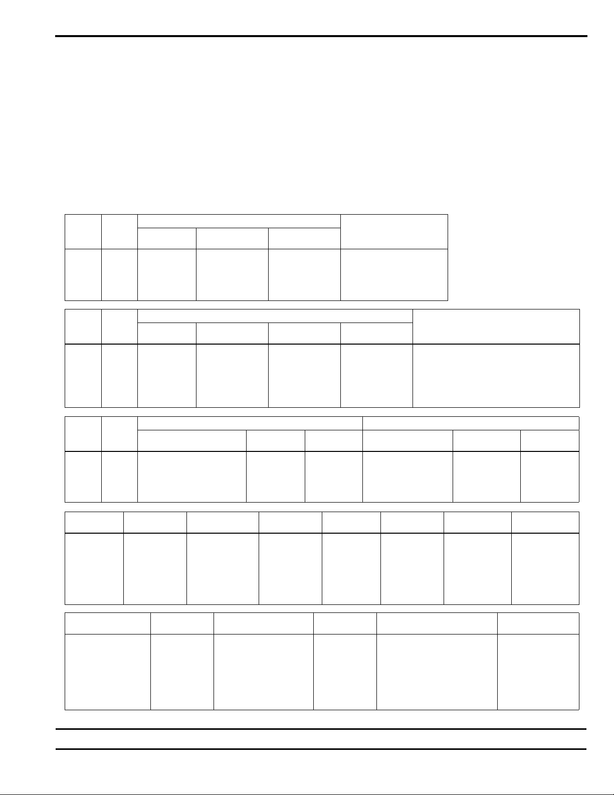
After establishing the proper system operation the appropriate
system operating conditions should be recorded for future reference.
Controls Operation
All other systems should be operating properly before the
controls function is tested.
Approved unit submittals, order acknowledgement, and other
manuals should be consulted for detailed information regarding
each individual unit and its controls. Care should be taken that
the correct control procedures have been identified for the unit
in question before any attempt is made to adjust the control
sequence. For specific information on controls provided by other
manufacturers contact the manufacturers local or national office.
This applies whether the controls are factory or field mounted.
Normal Operation & Periodic Maintenance
General
Each unit on a job will have it’s own unique operating environment
and conditions that will dictate the maintenance schedule for that
unit. A formal schedule and maintenance log and an individual
unit log should be established and maintained to establish max
performance and service life.
Information regarding safety precautions contained in the preface
at the beginning of this manual should be followed during any
service and maintenance operations.
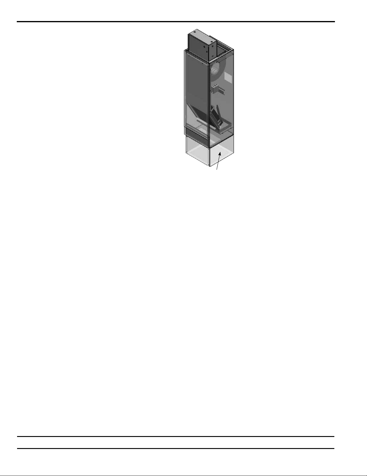
Motor Blower Assembly
Nailor uses permanently lubricated ECM motors to ensure a long
trouble free blower life. However, should it become necessary,
the blower assemblies in these units are easily removable.
Before the blower assembly can be slid from the unit, the wiring
harnesses between the motor and the unit must be unplugged.
To remove the assembly, first remove the two sheet metal screws
securing the blower assembly. Next, slide the blower assembly
out the front of the unit. To reinstall the blower assembly repeat
the removal sequence in reverse order, making sure to reconnect
all wiring harnesses.
Dirt and dust should not be allowed to accumulate on the blower
wheel or housing. This can result in an unbalanced blower wheel
and damage the wheel or motor. The wheel can be cleaned
periodically with a vacuum cleaner and brush.
Maintenance Procedures
If fan motor does not run, do the following:
a. Check for free rotation of blower wheel. Make sure no foreign
objects are in fan. Look for signs of freight or job site damage.
c. Check power supply. Disconnects should be in the “ON”
position.
d. Optional fusing should also be inspected. Check transformer
for proper output.
e. Check for proper control signals and fan relay function.
Fan motor runs but emits excessive noise:
a. Maximum airflow may be too high, or discharge static
pressure may be incorrect.
b. Blower may have clearance problems. Make sure all
components are securely attached.
c. Verify integrity of ductwork. Leaks or loose connections
could cause noise. Check for rattling diffusers or rattling or
incorrectly adjusted balancing dampers.
Fan motor runs, but airflow too low:
a. May be due to ductwork restrictions, dirty air filters, or clogged
water coils.
b. Readjust fan speed control.
c. Discharge static pressure may be incorrect.
Coil
Coils may be cleaned by brushing the coil face with a soft brush.
The brush strokes should be in the direction of the fin never
across the fin. Cleaning with a vacuum cleaner should follow this.
If compressed air is available the coil may be cleaned by blowing
air through the coil from the leaving airside. Vacuuming should
follow this procedure also. Even coils that have the filter changed
on a regular basis still require cleaning periodically.
Electric Resistance Heater Assembly
Electric resistance heaters typically require no normal periodic
maintenance when unit air filters are changed properly. The two
most important operating conditions for an electric heater are,
proper air flow, and proper supply voltage. High supply voltage
or insufficient airflow will cause the heater strips to cycle on the
high side. The strip heaters are equipped with automatic reset
switches to prevent overheating of the unit. Once the switches
are tripped the heater will remain off until it cools past the lower
set point for the trip switches to reset. If the trip switches actuate,
the system should be checked and any problem found corrected.
Electrical Wiring and Controls
The electrical operation of each unit is determined by the
components and wiring of the unit and may vary from unit to unit.
The wiring diagram for the unit in question should be consulted
before attempting any repairs to the unit. When replacing any
component such as fuses, contactors, or relays, the exact type,
size and voltage should be used. All repair work must be done in
such a manner as to maintain the equipment in compliance with
governing codes and ordinances or testing agency listings. Any
deviation will void all factory warranty.
The integrity of all electrical components should be verified at
least twice during the first year of operation. Afterwards, all
controls should be inspected regularly for proper operation.
Valves and Piping
Valves and piping require no formal maintenance. Inspection
should be made for possible leaks during the course of normal
maintenance. Should a valve require replacement care should be
taken to keep the valve cool during the brazing process.
Filters, Throwaway
The throwaway filters used on a fan coil should be replaced
on a regular basis. A log should show the time between filter
changes so a maintenance schedule for changing the filters can
be established.
Drain
The drain should be checked for blockage at the initial start up of
the unit and every year at the beginning of the cooling season. If
clogging is discovered steps must be taken to clear it before the
unit is started.
Periodic checks should be made during the cooling season to
maintain free flowing condensate. Should algae and/or bacteria
be a concern a local air conditioning and refrigeration supply
organization familiar with local conditions should be consulted for
what chemicals are available to control these agents.

Engineered Comfort reserves the right to change any information concerning product or specification without notice or obligation.
Dimensions are in inches (mm).
EC-39MUINST Date:1-24-24 Supersedes:5-6-10 Page 5 of 6
Replacement Parts List
Door Disconnect
Switch Part Number Disconnect
Switch Part Number Transformers Part Number
3P, 25A, 600V VH1-204 Toggle, 1P, 16A, 600V VH1-212 208/240/24V, 50VA VH1-685
3P, 60A, 600V VH1-205A Toggle, 3P, 40A, 600V VH1-211 277/24V, 40VA/50VA/75VA VH1-675/674/677
Toggle, 3P, 60A, 600V VH1-213 346/24V, 40VA/50VA/75VA H1-992/991/993
480/24V, 50VA VH1-686
120/208/240/480V, 75VA VH1-689
120/24V, 40/50VA VH1-669/692
Fan Relays Part Number Airflow Switch Part Number P.E. Switch Part Number Fan Motor
Fuses Part Number
1 Pole, 24V H1-666 AFS VH1-236A Switch, P-E H1-539 250V, 15A VH1-320
AFS Probe, 4" VH1-242 250V, 20A VH1-321
AFS Probe, 8" VH1-245 600V, 15A VH1-329
600V, 3A VH1-0011
600V, 5A VH1-965
600V, 8A VH1-967
Model
Series
Unit
Size
Standard Return Air Filters Filters for Filter Grilles Options
Nom.
Filter Size
Throwaway
Part Number
Merv. 7
Part Number
Nom.
Filter Size
Throwaway
Part Number
Merv. 7
Part Number
39MU
3, 5, 6 13 1/8 x 16 3/4 (333 x 425) VH1-1842 VH1-1352 14 x 14 (356 x 356) VHI-2000 VH1-1996
8, 10 15 1/2 x 24 (394 x 610) VH1-1843 VH1-1230 16 x 20 (406 x 508) VHI-2001 VH1-1997
12, 15 18 1/2 x 29 (470 x 737) VH1-1969 VH1-1967 20 x 25 (508 x 635) VHI-2002 VH1-1998
19, 21 24 1/2 x 29 (622 x 737) VH1-1970 VH1-1968 25 x 25 (635 x 635) VHI-2003 VH1-1999
Model
Series
Unit
Size
PSC Motor GE Blower Assembly
Part Number
HP 120V
Part Number
208 - 230V
Part Number
277V
Part Number
39MU
3, 5 1/10 VH1-1806 VH1-1807 VH1-1808 VH1-1809 (Size 3), VH1-902A (Size 5)
6, 8 1/6 VH1-1806A VH1-1807A VH1-1808A VH1-900Z (Size 6), VH1-1983 (Size 8)
10, 12 1/3 VH1-1806C VH1-1807C VH1-1808C VH1-904 (Size 10), VH1-1338 (Size 12)
15 1/2 VH1-1806D VH1-1807D VH1-1808D VH1-1925
19, 21 3/4 VH1-1806E VH1-1807E VH1-1808E VH1-1926 (Size 19), VH1-1925 (Size 21)
Model
Series
Unit
Size
ECM Motor GE Blower Assembly
Part Number
HP 120/208/240V
Part Number
277V
Part Number
39MU
6 1/3 VH1-0046B VH1-0045B VH1-900
10 1/2 VH1-0046A VH1-0046 VH1-904
15 3/4 VH1-0045A VH1-0045 VH1-904
19 1 VH1-0046E VH1-0045E VH1-904
Replacement Parts
Factory replacement parts should be used wherever possible
to maintain the unit performance, operating characteristics, and
testing agency listings. Replacement parts can be purchased
through the local Sales Representative. Any modification not
authorized by the factory could result in personal injury, damage to
the unit and will void all factory warranties.
When ordering parts the following information is required to ensure
proper part identification:
1) Complete unit model number.
2) Unit hand connection (right or left hand). Hand is decided by
standing in the entry air stream with the air striking the back of the head
.
3) Complete part description including any numbers available on
the part.
4) The SO# that appears on the nameplate label.
Any unit returned to the factory MUST have a Return Authorization
Number, provided by the factory, marked on it.
All equipment and components sold as replacement parts or
sent as a warranty part are warranted for 12 months from the
date they leave the factory.

Fan Coil Units engineered-comfort.com
Houston, Texas
Tel: 281-590-1172
Fax: 281-590-3086
Supersedes:5-6-10 Date:1-24-24 EC-39MUINST
Dimensions are in inches (mm).
Toronto, Canada
Tel: (416) 744-3300
Fax: (416) 736-4262
Page 6 of 6
Table of contents
Popular Air Handler manuals by other brands

York
York AHU Operation and maintenance

Suntherm
Suntherm SEHX Series installation manual

Lennox EMEA
Lennox EMEA ARIA 2 Installation, operating and maintenance

Euroclima
Euroclima ZHK NANO instruction manual

Lennox
Lennox INALTO Installation, operation and maintenance

Parameter Generation and Control
Parameter Generation and Control 9354-4250 Installation and operation manual

Alphacool
Alphacool ES Orbiter 360 TS manual

Kampmann
Kampmann KSW Assembly, installation and operating instructions

Mars
Mars Comfort-Aire Century B-VMH AV-1 Series installation manual

BLAUBERG Ventilatoren
BLAUBERG Ventilatoren CIVIC EC DB user manual

Rec Temovex
Rec Temovex G10125 user manual

Nordyne
Nordyne P6SP Series User's information manual