Remak AeroMaster Cirrus Series User manual

Air Handling Units
INSTALLATION AND OPERATING INSTRUCTIONS 05/2015

2
Air Handling Units
Contents
Application, Operating Conditions and Construction ......................................................................................................................................... 3
Manufacturer‘sNotication ........................................................................................................................................................................... 3
Application and Operating Conditions .......................................................................................................................................................... 3
Air-Handling Unit Construction ..................................................................................................................................................................... 3
Air-Handling Unit Marking............................................................................................................................................................................. 3
Information and Safety Labels ...................................................................................................................................................................... 3
Side Variability of Unit Connections.............................................................................................................................................................. 3
Goods Despatch...................................................................................................................................................................................................... 4
Delivery Content ........................................................................................................................................................................................... 4
Transport and Storage.................................................................................................................................................................................. 4
Packaging ..................................................................................................................................................................................................... 4
Transport and Handling of Air Handling Unit Components ........................................................................................................................... 4
Rotary Heat Exchanger Transport ................................................................................................................................................................ 4
Storage Conditions ....................................................................................................................................................................................... 4
Installation................................................................................................................................................................................................................ 5
Installation Site ............................................................................................................................................................................................. 5
Service Access ............................................................................................................................................................................................. 5
Pre-Installation Inspection ............................................................................................................................................................................ 5
IdenticationofAir-HandlingUnitComponents ............................................................................................................................................ 5
Assembly of Air-Handling Unit Sections ....................................................................................................................................................... 6
Assembly of Base Frames............................................................................................................................................................................ 6
Assembly of Individual Sections ................................................................................................................................................................... 6
Rotary Heat Exchanger Block Alignment...................................................................................................................................................... 7
Connection of Heat Exchangers ............................................................................................................................................................................ 9
Water Heat Exchangers................................................................................................................................................................................ 9
Connecting Dimensions of Water Heat Exchangers..................................................................................................................................... 9
Direct Evaporators ........................................................................................................................................................................................ 9
Connection of Direct Evaporators................................................................................................................................................................. 9
Water Connected Air-handling Component Installation .............................................................................................................................. 10
Condensate Drainage................................................................................................................................................................................. 11
Other Connections ................................................................................................................................................................................................ 11
Air-handling Duct Connection ..................................................................................................................................................................... 11
Electric Equipment Wiring........................................................................................................................................................................... 11
Wiring of Motors.......................................................................................................................................................................................... 12
Wiring Diagrams – Fan Motors ................................................................................................................................................................... 12
Wiring Diagrams – Electric Heaters............................................................................................................................................................ 12
Commissioning...................................................................................................................................................................................................... 13
Safety precautions ..................................................................................................................................................................................... 13
Protection against Dangerous Contact with Non-Live Parts....................................................................................................................... 13
Inspection Prior the First Start-Up .............................................................................................................................................................. 13
Checking During the First Start-Up............................................................................................................................................................. 13
Service regulations ..................................................................................................................................................................................... 12
Operating Checks and Service Regulations....................................................................................................................................................... 14
Unit Operation - Service Regulations ......................................................................................................................................................... 14
Unit Operation Screening Checks .............................................................................................................................................................. 15
Regular Inspections .................................................................................................................................................................................... 15
Filter Replacement...................................................................................................................................................................................... 17
Spare Parts and Service ....................................................................................................................................................................................... 20
Spare parts, Service, Disposal ................................................................................................................................................................... 20
Complementary Information .................................................................................................................................................................................... 21
Covering Roof Assembly ............................................................................................................................................................................ 21
Gas Heater Section .................................................................................................................................................................................... 27
Integrated Cooling Section ......................................................................................................................................................................... 28
Supplementary information - Pool design of units, 2nd Generation ........................................................................................................... 29
Replacementoffabricsinsideofinsertlter............................................................................................................................................... 31
General Information
AeroMaster Cirrus air-handling units are manufactured in accordance with valid Czech and European regulations and technical standards.
AeroMaster Cirrus air-handling units must be installed and used only in accordance with this documentation.
The manufacturer is not responsible for any damage resulting from use other than intended, and the customer bears the risks of such use.
The installation and operating documentation must be available for the operating and servicing staff.
It is advisable to store this documentation close to the installed air-handling unit.
When handling, installing, wiring, commissioning, repairing or servicing the air-handling units, it is necessary to observe valid safety rules,
standards and generally recognized technical rules. In particular, it is necessary to use personal protective work aids (e.g. gloves) because
of sharp edges and corners when performing any handling, installing, dismounting, repairing or checking. All equipment connections must
comply with the respective safety standards and regulations.
AnychangesormodicationstoindividualcomponentsoftheAeroMasterCirrusair-handlingunitswhichcouldaffectitssafetyandproper
functioning are forbidden.
Before installing and using the air-handling units, it is necessary to familiarize yourself with and observe the directions and
recommendations included in the following chapters.
AeroMaster Cirrus air-handling units, including their individual parts, are not intended, due to their concept, for direct sale to end customers.
Eachinstallationmustbeperformedinaccordancewithaprofessionalprojectcreatedbyaqualiedair-handlingdesignerwhois
responsible for the proper selection and dimensioning of components concerning their suitability for a given application. The installation and
commissioning may only be performed by an authorized company licensed in accordance with generally valid regulations.
When disposing of components and materials, it is necessary to observe the respective environmental protection and waste disposal
regulations.Incaseofnaldeviceliquidation,itisnecessarytofollowthepolicyofdifferentialwastedisposal.Werecommendmetalparts
be scrapped and other parts be disposed of in accordance with separated waste regulations.
The latest version of this document is available on our website: www.remak.eu

3
Air Handling Units
Application, Operating Conditions and Construction
Manufacturer‘s Notication
AeroMaster air-handling units are manufactured in accor-
dance with valid Czech and European regulations and
technical standards. AeroMaster air-handling units must be
installed and used only in accordance with this documen-
tation. The installation and operating documentation must
be available for the operating and servicing staff, and it is
advisable to store this documentation close to the installed
air-handling unit.
Application and Operating Conditions
AeroMaster Cirrus air-handling units are designed for
comfortableair-handlingandair-conditioninginanairow
range corresponding to the air-handling unit’s cross-sec-
tionandrequiredairowvelocityfrom1.5-4m/satanair
pressure difference of the fan of up to 2500 Pa. The air-
-handling unit is designed as a modular system with a fra-
meandlaminatedconstructionwhichenableshighexibi-
lity.Thusindividualmodicationtocustomerrequirements
is possible. Inner width (W), height (H) and length (L) are
multiples of the module (N × 306 mm) and create space for
the installation of built-in functional assemblies.
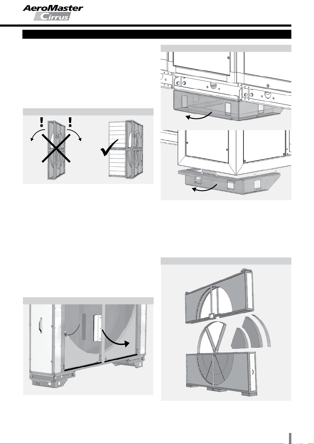
AeroMaster Cirrus air-handling units are intended for
installationonoorsorsubstructures,andaredelivered
with a rigid base frame mounted in the factory.
Theyaredesignedtotransportairwithoutsolid,brous,
sticky, aggressive or explosive impurities. The transpor-
ted air must be free of corrosive chemicals or chemicals
aggressive to zinc and steel, respectively aluminium.
They are manufactured with the same construction for
inside as well as outdoor environments, including units
designed for rooms with greater requirements for cleanli-
ness. Air-handling units intended for outside environments
are completed with suitable accessories (roof, louvers,
etc.) ensuring correct and failure-free operation. With the-
se air-handling units, the correct selection, localization and
connection of the M&C components, including anti-freeze
protection, must be ensured.
AeroMaster Cirrus air-handling units can be used in
normalrooms(IEC60364-5-51,resp.ČSN332000-5-
51ed.2,ČSN332000-1ed.2)andinroomswithexten-
ded ambient temperature range from -30 °C to + 40 °C
without additional measures - applies to the standard
version. Custom-made units with decreased -40 °C to
+40 °C or increased -30 °C +50 °C temperature range
of transported air can be delivered.
When designing the air-handling assembly, it is
necessary to take into account the temperature and
humidity of the inlet and outlet air in relation to the
ambient temperature and humidity. It is especially
necessary to analyze the relation of the unit's casing
classicationpursuanttoEN1886andtheriskofcon-
densation, respectively ice build-up.
The device can be used for outdoor installations if
equipped with a protecting roof; the device is water
spray proof (rain up to 60° vertical slant) while obser-
ving the Installation and Operating Instructions.
The fans are equipped with motors insulated with F
class insulation of the winding.
The unit's noise level does not exceed max. allowed
valuesasperStatutoryOrderNo.176/2008Sb,Appen-
dix No. 1, Article 1.7.4.2., Letter u).
Air-Handling Unit Construction
The air-handling unit is designed as a modular system
with a frame and laminated construction. The walls consist
oftwolayersofuniedmodularlaminasattachedtothe
frame.Therstlayeroftheupper,lowerandbackwalls
has longitudinally-oriented laminas while the second la-
yerlaminasarecross-oriented.Thefrontwallttedwith
service panels has laminas oriented in the same direction
in both layers. The service parts (panels) are also of la-
minated construction. Each panel consists of the external
casing with integrated reinforcements.
The panels which are expected to enable occasional servi-
ce access to the internal built-in assemblies are provided
with locks and grab handles to make handling easier. The
panelsusedforregularservicing(replacementoflter
inserts, cleaning of built-in assemblies, etc) are provided
with hinges and locks.
All walls are of sandwich construction with a total insu-
lation thickness of 50 mm. They are provided with a quality
anti-corrosionsurfacenish.Theconnectionsbetween
walls, panels and supporting cross-members are sealed
with a seal with closed cell structure.
The seals used during the assembly of the air-handling
unit’s lamellar walls and casing have a closed cell structu-
re. The non-glued replaceable sealing of the service pa-
nelsisttedintothegrooveontheinnersideofthepanel.
Internal casing: Standard version - galvanized sheet
steel, optionally painted sheet steel (polyester paint) or
stainless sheet steel
External casing: Standard version - galvanized sheet
steel, optionally painted sheet steel (polyester paint) or
stainless sheet steel
Frameproles:Standardversion-hot-dipgalvanized
sheet steel, optionally painted sheet steel (polyester paint)
Insulation of the upper and side panels is made of 50
mm thick non-combustible mineral wool (Class A1 pur-
suantČSNEN13501-1).
Insulation of the lower panels is made of 50 mm thick
PUR foam boards (Class B2 pursuant DIN 4102).
The joints are sealed with silicone compound.
Air-Handling Unit Marking
The complete AeroMaster Cirrus air-handling unit is
divided into "structural" BLOCKS, respectively transport-
installationBLOCKS.Functionally,theblockisdenedby
the internal built-in assembly (assemblies) which is (are)
ttedintotheblock'scasing,wherethecasingiscreated
with laminated walls, supporting cross-members and a
combination of service panels situated on the access side
of the unit.
The air-handling unit is then assembled from the trans-
port-installation blocks at the installation site. At the outlet,
thetransport-installationblocksarettedwithanendpanel
or a frame to be connected to the next block.
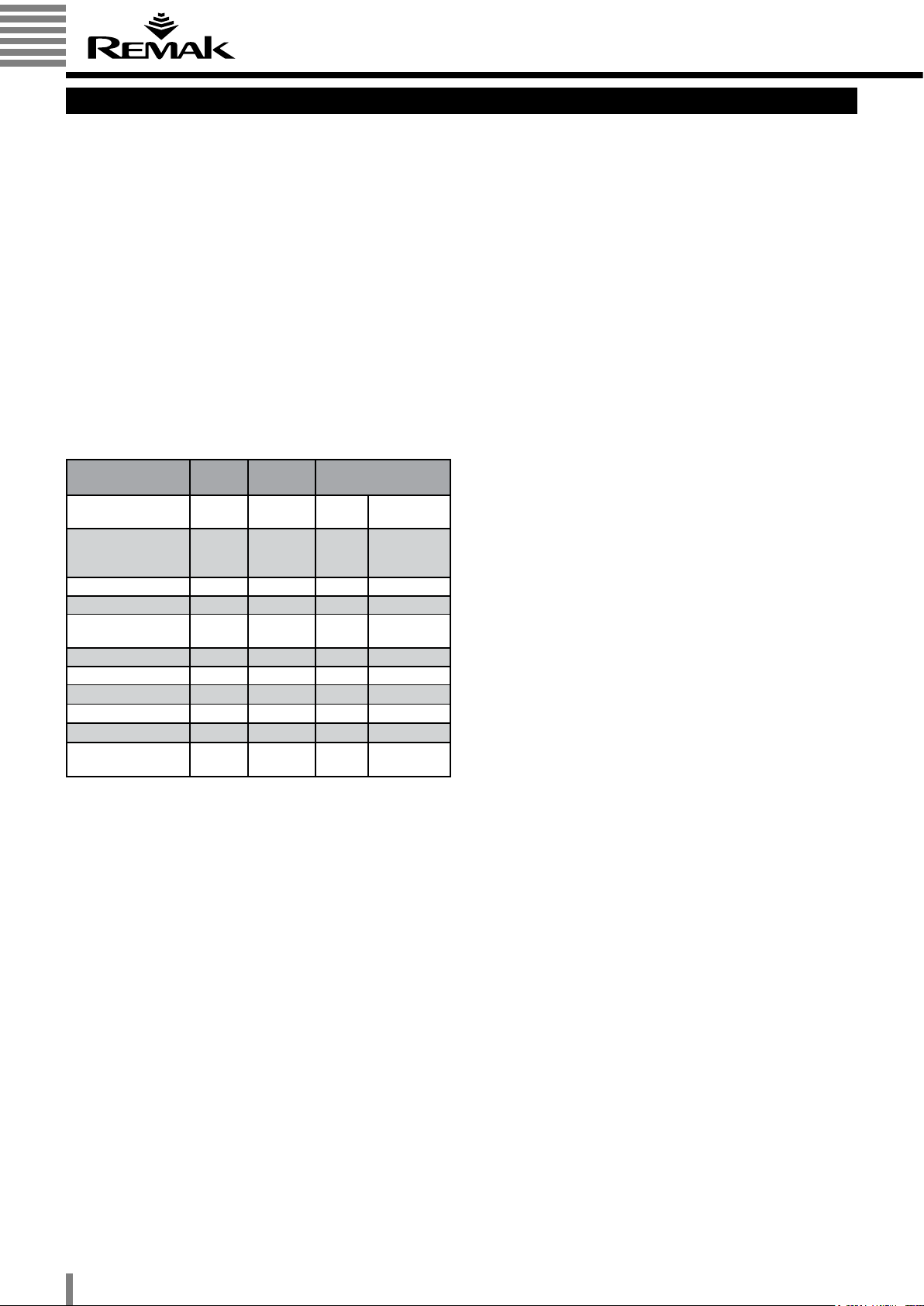
BLOCK is provided with a BLOCK type (name) plate
indicating the following data:
Manufacturer's name (incl. logo) and address
Type, size and marking code of the BLOCK
BLOCK serial number
Ordernumber(serialnumber)/yearofproduction
Weight

4
Air Handling Units
Despatch
Side Variability of Unit Connections
Connectionsideisalwaysdeterminedbytheair-ow
direction:
Transport and Handling of Components
Air-handling units are transported to the installation site
either as transport-installation blocks or disassembled (for
transport and handling of disassembled units, refer to the
separate manual).
Loading, unloading and handling can be performed by a
fork-lift truck, a manipulating carriage or a crane. If lifted
by crane, spacer bars must be inserted between the lifting
wires to protect the air-handling unit from being damaged.
If air-handling unit blocks without a base frame are han-
dled,fork-lifttruckforksofasufcientlengthmustbe
used to overreach the full depth of the lifted block. If the
air-handling unit block with a base frame is handled, forks
ofasufcientlengthmustbeusedtooverreachbothside
beams of the base frame.
Figure 2 – Handling options
The "Other Danger" warning label situated on the face
side of the service door indicates the hazard of catching
by movable parts.
The service panels covering electrical equipment are
labelled with a "Warning – Danger of Electric Shock"
warning label.
Information and safety labels
AeroMaster CIRRUS air-handling units, respectively indi-
vidual sections, are also labelled with information labels
indicating equipment operation, wiring diagrams, energy
media inlets and outlets and logos of the manufacturer.
Delivery Contents
The following items are enclosed with every delivery of
the air-handling unit:
Accompanying technical documentation
(Installation and Operating Instructions)
Commercial and technical documentation, including
air-handling unit assembly drawing
Connecting material kit
Installation kit
Measuring & control components, respectively
accessories in accordance with the bill of delivery
Transport and Storage
Air-handling units with a base frame of standard height
(85mm) are dispatched on a pallet or transportation
prisms.
Air-handling units equipped with a raised base frame
(with supporting legs) are dispatched without additional
handling means.
Packaging
As standard, the transport blocks of the Cirrus air-handling
units are packed in PE foil and provided with cardboard
and polystyrene protecting guards. The holes in the base
frame can be used to lift the unit by a crane.
Figure 1 – side variability of unit connections
LEFT-HAND VERSION RIGHT-HAND VERSION
Air-ow
direction
Figure 3 – Handling holes in base frame
Each built-in assembly is marked with a type (name)
plate situated on the service panel side. The name plate
includes the technical parameters of the given built-in as-
sembly. The user must ensure that every marking on the
unit components will be readable and intact for the whole
service life of the unit. If damaged, especially if safety is
concerned, the marking must be repaired immediately.

5
Air Handling Units
Installation
Storage Conditions
As standard, the air-handling units are packed in PE foil.
They must be stored in indoor rooms complying with the
following conditions:
Maximum relative air humidity must not exceed 85%.
No moisture condensation.
Ambient temperature must be in the range
-20°C to+40°C.
The air-handling units must be protected against pene-
tration of dust and caustic vapours, or other chemical sub-
stances which could cause corrosion of the air-handling
unit’s structural components and equipment.
The air-handling units must not be exposed to the
direct effects of solar radiation.
AeroMaster Cirrus air-handling unit blocks may only be
stored in the same position in which they are operated.
Prior to installation, the following must be
checked
Delivery completeness
Delivery integrity
Volubility of rotary components
(fans, dampers, rotary heat exchanger)
Parameters of the power supply and connected energy
media sources
Any found fault must be removed before starting the
installation.
Figure 5 – service access
Keep these distances from the wall to enable service and access:
0.8 x width (W) of the air-handling unit: fan
1.15 x width (W) of the air-handling unit: heater, cooler, drop
eliminator,lter,plateheatexchangerandrotaryheatexchanger.
Every service access can be visualized in the AeroCAD program.
Identication of Components
The association of blocks and built-in assemblies to the
particular purchase order number is indicated on the name
plate of each block and built-in assembly, i.e. device num-
ber. All blocks bearing the same device number create
an air-handling unit. The manner of the blocks' assembly
is apparent from the assembly drawing included in the
accompanying technical documentation (respectively our
offer) marked with the same order (device) number.
Air-Handling Unit Location
The surface of the site for the air-handling unit installation
mustbelevelandat.Maximummisalignmentoftheoor
or supporting structure intended for the air-handling unit
installation must not exceed 1 mm per 1 meter. Observan-
ce of this condition is important for installation as well as
for the air-handling unit operation. The air-handling unit
equipped with an integrated base frame does not need any
special anchoring. It is advisable to ground the air-handling
unit with grooved rubber stripes.
When installing the gas heater block, it is necessary to
maintainsafetydistancesfrominammablematerials
in accordance with national directives and standards of
thestateofinstallation(intheCzechRepublic–ČSN06
1008).Noinammablematerialsareallowedtobestored
within the area of the gas heater block installation
Warning: The base frame or base frame and founda-
tion height should respect the condensate drainage
siphon height if not resolved in another way (e.g. em-
bedding into the oor or installation on an additional
base frame of the required height).
Service Access
When planning the air-handling unit location, it is necessa-
rytokeepsufcientspaceformaintenance,serviceand
operating. The need for this space depends on the air-han-
dlingunitconguration,i.e.ontheoperationalblocksused.
The air-handling unit blocks are packed in PE foil.
Warning: When transporting, respectively handling
the air-handling unit blocks, it is necessary to pay inc-
reased attention to those parts (pipes, closure valves,
etc.) projecting from the walls of the air-handling unit
block. All blocks may only be transported in the same
position in which they are operated!
Rotary Heat Exchanger Handling
Increased attention must be paid to the safety of persons
as well as of the product when handling the rotary heat
exchanger block, which due to its dimensions (tall and
narrow), weight and high centre of gravity is very unstable.
Themanufacturerrecommendsalwaysxingtherotary
heat exchanger in position by suitable roping if it is not as-
sembled in the block assembly! The rotary heat exchanger
can only be stored, transported or handled in the vertical
position.Anytiltingmaydamagetherotoratness.
Particular distances for the CIRRUS air-handling units:
Fan 0,8 x width*
Heater, cooler, eliminator 1,15 x width*
Filter 0,8 x width*
Plate heat exchanger 1.15 x width*
Rotary heat exchanger 0,8 x width*
* width of the built-in assembly
Figure 4 – Rotary heat exchanger handling options
do not tilt!

6
Air Handling Units
Assembly of unit blocks
Connection of Individual Blocks
Paste the rubber sealing (19 x 4) onto the contact surfaces
of the connecting frame.
Push the connected blocks against each other and screw
the blocks together in the corners of the connecting frame
using M8 x 40 bolts
(seegure).
If the stacked arrangement of the air-handling unit blocks
is used, an additional connection will be necessary - using
the upper block's base frame.
Connection of
Unit Blocks
The air-handling unit
blocks can be assem-
bled together by
connecting their base
frames and connecting
the respective blocks.
Connection of
Base Frames
Connection of base
frames using M8x20
bolts. The bolts and other connecting materials are inclu-
ded in the installation kit
Figure 6 – connection detail
Figure 9 – Internal connection of blocks
Figure 7 –Sealing between blocks
M8 × 30
M8 × 40
contact surfaces
of the connecting
frame to be glued
with rubber seal
18 x 4 mm
Figure 8 – Screw Head Caps
see above
Screw Head Caps
After the air-handling
unit blocks have been
connected, the screw
head caps have to be
ttedonallthepanels
on the air-handling unit
service side.
Warning: When connecting the transport and handling
blocks of the air-handling unit, do not remove the rear
laminated walls - they are an integral part of the casing
structure!

7
Air Handling Units
Rotary Heat Exchanger Block Alignment
Alignment procedure
Attention!
Due to its dimensions, the rotary heat exchanger
is very easy to roll over! Even the slightest impact or
rocking can cause the exchanger to fall.
Make sure the assembled heat exchanger is not left
without being secured against fall.
To secure the heat exchanger, use fastening straps or
connect the adjacent chambers to the exchanger.
Depending on the air-handling unit base frame height
and heat exchanger size, the heat exchanger can be
equipped with transport legs to make its handling
easier.
Figure 11 – Transport brake removal
Figure 13 – Disassembled Heat exchanger
Figure 10 – Exchanger securing and risk of falling
Figure 12 – Transport legs
The rotary heat exchanger can be transported using
common transport means while the rotary heat
exchanger must always be secured in the vertical
position (i.e. the axis of rotation is in the horizontal
position).
It is advisable to start with this (the heaviest) block when
placing the assembly blocks in position. Immediately co-
nnect the rotary heat exchanger to the adjacent chamber
to prevent it falling. Before connecting it to the adjacent
chamber,placethesealontheconnectionframe(seegu-
re # 7).
Warning:
The rotary heat exchanger is equipped with a transport
brake which secures the rotor against free movement
during transport and handling. This brake must be
removed!
These legs must be removed before heat
exchanger alignment!
Larger heat exchangers are transported disassembled.
The delivery includes separated lower and upper half of
the frame and segments of the rotor. Installation and com-
missioning of the device can only be performed by a profe-
ssional installation company trained or authorized to carry
out this work by the manufacturer.
Everyrotaryheatexchangeristtedwith
“THIS SIDE UP! and “FRAGILE” labels

8
Air Handling Units
Rotary Heat Exchanger Block Alignment
Warning:
Poorand/orincorrectinstallationoftherotaryheatex-
changer block can result in costly repairs. It will result in
rotordisplacement,whichwillinuencethetightnessand
service life of the assembly. Misalignment can be caused
by improper handling during transport or failing to observe
the conditions for correct installation. To check heat ex-
changer rotor fouling, it is necessary to perform regular
monitoring of the heat exchanger rotor pressure loss. The
heat exchanger rotor pressure loss must not exceed 15%
of the pressure loss value measured on a new rotary heat
exchanger. To enable regular servicing, maintenance,
guarantee and post-guarantee service, it is necessary to
provide a service access from both sides of the heat ex-
changer's rotor.
Figure 14 – of the heat exchanger to the assembly
Figure 15 – Frame connection detail

9
Air Handling Units
Connection of Heat Exchangers
Water and Glycol Heat Exchangers
The heat exchangers can be delivered in versions to be
connected:
a)throughthexedsidepaneloftheair-handlingunit
b) into the inner cross-section:
Figure 16 – Heating and cooling media feed
The corresponding connection points are marked with
labels on the unit side panel (heating water inlet, heating
water outlet, coolant inlet, coolant outlet).
The connection diameter corresponds with the heat
exchangerandgiventypeparameters,anditisspeciedin
the air-handling unit documentation. Available dimensions
are from G1" to G3".
TheheadersareequippedwithG3/8"necksfortheair-
venting valve in the upper part of the heat exchanger;
these necks also enable an antifreeze protection sensor to
be installed (on the exchanger outlet header) or the heat
exchanger to be drained.
Figure 17 – Anti-freeeze protection sensor
Connection of Water Heat Exchangers
The counter-current connection of the heat exchangers
is necessary to achieve maximum output. When con-
nectingthefeedingttingstotheheatexchangers,usetwo
wrenches to tighten the screws to avoid wresting of the
exchanger's headers.
After connecting the water heat exchangers (heaters and
coolers, including mixing sets) to the distribution piping,
itisnecessarytopressurize(llwithwater)andventthe
entire circuit, including the heat exchanger, and then to
perform leak-tightness checks of all pipe joints and of the
exchanger itself (including inspection of the water exchan-
ger block interior).
The manufacturer does not provide any guarantee
covering any damage resulting from liquid leakage from
leaky joints or damaged exchangers.
Figure 18 – Heat exchanger connection
Figure 19 – Glycol circuit connection
Figure 20 – Connection of evaporators
Direct Evaporators
Direct evaporators must be connected by a specialized
contractor authorized to install refrigerating equipment.
The direct evaporators can be delivered in versions to be
connectedthroughthexedsidepaneloftheair-handling
unit or into the inner cross-section.
Thedirectevaporatorsarelledwithnitrogeninthefacto-
ry. They can be delivered in single or multiple-circuit versi-
ons.
NECKS for installation of the antifreeze pro-
tection sensor and air-venting valve
A i r o w d i r e c t i o n
(cooler right-hand
version)
A i r o w d i r e c t i o n
(cooler
right-hand
version)
Inlet
Outlet Inlet
Outlet
Glycol cooler Glycol heater
1) Circulation pump
2) Air-venting valve
3)Inlet/outletvalve
4) Safety valve
5) Expansion tank
6) Pressure gauge
3 1 3
2 4 5 6 2
Double-circuit evaporator Double-circuit evaporator
inlet
outlet
Single-circuit evaporator
inletoutlet
Single-circuit evaporator
1
2
1
2
1
2
1
2A i r o w d i r e c t i o n
(cooler right-hand
version)
A i r o w d i r e c t i o n
(cooler right-hand
version)
A i r o w d i r e c t i o n
(cooler right-hand
version)
A i r o w d i r e c t i o n
(cooler right-hand
version)

10
Air Handling Units
Connection of Heat Exchangers
Water Connected Air-handling Component
Installation
Recommendations on water quality for heat exchangers
that operate using low pressure hot water (LPHW) and
chilled water:
A good water quality – e.g. salt and lime-free drinking
water – increases the
lifetimeandefciencyoftheheatexchanger.
Check the limiting values shown in the table annually to
prevent damage to
the hydraulic system and its components.
If necessary inhibitors must be added.
Note:
These limiting values are only basic information about the
water quality and do not form any basis for a guarantee!
1/1,78°D=1°Fr,with1°Fr=10gCaCO3/m3
ppm=partspermillion(mg/l)
ppm=partsperbillion(µg/l)
Description Symbol Values Effects in vent
of deviation
Hydrogen ion
concentration pH 7,5 - 9 < 7
> 9
Corrosion
Fouling
Calcium and
magnesium content
Hard-
ness
(Ca/Mg)
4 – 8,5 °D > 8,5 Fouling
Chloride ions Cl- < 50 ppm Corrosion
Carbon dioxide Fe3+ < 0,5 ppm Corrosion
Iron ions Mg2+ < 0,05
ppm Corrosion
Carbon dioxide CO2< 10 ppm Corrosion
Hydrogen sulphate H2S < 50 ppb Corrosion
Oxygen O2< 0,1 ppm Corrosion
Chlorine Cl2< 0,5 ppm Corrosion
Ammonia NH3< 0,5 ppm Corrosion
Ratioofcarbons/
sulphates
HCO3
2- /
SO4
2- >1 <1 Corrosion

11
Air Handling Units
Connection of Heat Exchangers, Duct, Wiring
Steam Humidication
For a detailed description of installation, commissioning
andprescribedinspectionsofthesteamhumidication
built-in assembly, refer to the separate manual which is
a part of the accompanying documentation of the Aero-
Master Cirrus air-handling unit.
Wheninstallingthesteamhumidicationassembly,obser-
ve the following recommendations:
Air ducts leading through cold areas must be insulated
to avoid condensation.
The assembly must be situated in a non-freezing area.
The steam generator can be noisy (switching of soleno-
id valves); therefore, it is advisable to install it away from
quiet areas.
100°C hot and heavily mineralized water is drained
fromthesteamhumidier.
The following minimum distances (distances between
thesteamhumidierandthefollowingair-handlingunit
components, where H represents the minimum evapora-
ting distance calculated for the given conditions) must be
observed to ensure proper operation of the steam humidi-
erandtheentireAeroMasterCirrusair-handlingunit:
Humidistat piping, humidity sensor, temperature sen-
sor: 5x H
Verynelter:2.5xH
Heatingelements,lter:1.5xH
Duct branch piece, duct elbow, air outlet, fan: 1x H
Note: If the H value is not known, it is advisable to make
the calculation with a minimum value of 1.0 m.
Condensate Drainage
Cooling,plateheatexchangerandsteamhumidication
blocks are equipped with stainless condensate draining
trays which terminate in an outlet for the condensate drai-
ning kit connection. The diameter of the neck for Cirrus air-
handling units is 32 mm. The condensate draining kits are
available as optional accessories. A separate condensate
draining kit must be used for each individual block.
The siphon height depends on the total pressure of the
fan, and ensures its proper functioning. The type of con-
densate draining kit must be designed in the course of
the air-handling unit calculation. The condensate draining
piping must end in free atmosphere, i.e. it must not end
directly in the closed sewerage system.
Before operating the air-handling unit or after being out
ofoperationforalongerperiod,itisnecessarytollthe
siphon with water. The air-handling unit can also be equip-
ped with a siphon with a disconnecting trap and a ball
valve (only negative pressure blocks). This type of siphon
neednotbelledwithwaterbeforeputtingitintooperati-
on. If there is a risk of freezing, it is necessary to insulate
the siphon and condensate draining piping, respectively
keep the ambient temperature above freezing point, e.g.
with an electric heating cable!
Figure 21 – condensate drainage
Siphon – positive pressure Siphon – negative pressure Siphon – negative pressure
(with a disconnecting trap)
Hmin (mm) = P (Pa) / 10 P – total fan pressure
The gas heater block is provided with a condensate drai-
nageoutlet(1/2"pipe)todrainthecondensatefromthe
combustion chamber.
Air-handling Duct Connection
The air ducting must be connected to the air-handling unit
via an elastic element to avoid the transfer of vibrations
and eliminate misalignment of the duct and inlet of the air-
handling unit. The connection must be performed so that
no loading from the air duct will be transferred to the inlet
panel of the air-handling unit and no deformation of this
panel will be possible.
The accessories must be installed in accordance with the
air-handlingunitspecicationandtheInstallationInstructi-
ons of the manufacturers of such accessories.
No other structures must obstruct the unit inspection door
opening, or unit operation and maintenance.
Electrical Equipment Wiring
Connection of the internal electrical equipment of the
air-handling unit can be made via the wiring grommets
which are situated on the service side of the air-handling
unit casing (the service side according to the designer's
specication).
All unused grommets must be blinded to maintain the
degree of protection.
The wiring and installation of the measuring & control
systemelementsmustbeperformedbyqualiedprofes-
sionals authorized to perform wiring of the given type of
devices. The wiring must be performed in accordance with
the directives and standards of the country of installation,
and in accordance with the Installation and Operating
Instructions of individual pieces of equipment (frequency
converters, pressure and temperature sensors, etc).
Before putting the air-handling unit into operation, a wi-
ring inspection must be performed.
Conformity of the power supply voltage, frequency and
protection with the data on the type plate of the connected
block and cross-section of the connecting cables must be
checked before connecting the electrical equipment to the
power supply.
The connecting cables must be long enough to allow
free movement (e.g. when tightening the V-belts).
Properlyxallcablesandkeepminimumbendingradi-
uses.
If additional grommets are to be installed, avoid
installation of grommets and cables close to the doors,
access panels and connections of the air-handling unit's
blocks.
The cables must never obstruct routine operation and
servicing. Please respect the reserved servicing space.
Screw connections and grommets must not cause air
leakage.
Figure 22 – cable wiring grommet design
The wiring grommet consists of a PG grommet,
distance piece and sealing

12
Air Handling Units
Wiring
Wiring of Motors
To ensure correct operation of the air-handling unit, the motors must be connected so that they will rotate in the
correct directions.
The motors are equipped with thermo-contacts which protect them against overheating. The thermo-contacts must be
connected as shown in the wiring diagram.
The fan built-in assembly can be equipped with a service switch. The service switch is delivered as an optional accessory
separately, not installed on the unit. The service switch connection must be performed in accordance with the directives
and standards of the country of installation, and in accordance with the Installation and Operating Instructions.
The fan assemblies of some dimensional ranges (74, 84, 94) are equipped with two independent fans. The fan motors
must be connected separately. 2 frequency inverters are delivered to control these fans.
Single-Speed Motors – Wiring Diagrams
Rated voltage and wiring for motors up to 3 kW,
including:230VD/400VY
Rated voltage and wiring for motors above 3 kW:
400VD/690VY
Two-Speed Motors – Wiring Diagrams
6/4polemotors–twoseparatewindingsY/Y(output,
respectively speed ratio 2:3)
Two-Speed Motors – Wiring Diagrams
8/4polemotors–DahlanderD/YY
(output, respectively speed ratio 1:2)
Electric Heaters
The electric heater connection must be performed fol-
lowing the instructions included in the enclosed documen-
tation, the wiring diagram.
Rotary Heat Exchangers
The rotary heat exchanger is equipped with a single-speed
motor. The connection must be performed following the
chapter Wiring of Motors (see above).
Additional Electrical Equipment
Additionalelectricalequipment,whichisnotspeciedin
this manual, must be connected in accordance with the
applicable documentation, a wiring diagram, which is inclu-
ded in the equipment delivery.
Speed 1:
750 rpm
Speed 2:
1500 rpm
Speed 1:
1000 rpm
Speed 2:
1500 rpm

13
Air Handling Units
Commissioning
Safety Measures
The blocks with built-in assemblies which can generate
certain injury hazards (electric shock, rotating parts, etc.)
andconnectionpoints(heatingwaterinlets/outlets,airow
direction, etc.) are always labelled with warning or informa-
tion labels.
It is forbidden to start the fans of the air-handling unit if
thepanelsareopenorremoved,orwithoutxedprotecting
guard covers. The hazard of trapping by movable parts is
indicated by a label situated on the service door of the air-
handling unit. Service doors must always be closed during
air-handling unit operation.
Before starting any work on the fan block, the main
switch must always be turned off and secured to avoid
accidental starting of the motor during service work on the
fan block.
When emptying the heat exchanger, the water tempe-
rature must be below +60 °C. The connecting piping of the
heater must be insulated so its surface temperature will not
exceed +60 °C.
It is forbidden to remove the service panel of the
electric heater if energized.
It is forbidden to operate the electric heater without the
outlet air temperature control and without ensuring a stea-
dyowoftransportedair.
Controlled run-down of the fans must be ensured
upon gas heater burner shutdown to avoid the exchanger
overheating, and simultaneously, the outlet air temperature
behind the gas heater, respectively the ambient temperatu-
re of the burner, must not exceed 40 °C.
After being set by an expert, the parameters of the gas
heater block must stay unchanged to maintain safe and
trouble-free operation.
Protection against Dangerous Contact with
Non-Live Parts
The protection against dangerous contact of non-live parts
is performed by design measures ensuring electrical con-
ductivity: spot-welds, screw joints with fan washers, inter-
connection with protective conductor (PE) in accordance
withČSNEN60439-1.
Inspection Prior to First Start-Up
The service panels are provided with hinges and external
closures. The closure simultaneously serves as a handle.
Aspecialtool–awrench-isneededtoopen/closethe
closure.
This wrench is delivered with each fan section and can
also be delivered as a spare part (code Z03410058).
Figure 23 – hinges and external closures
General Routines and Checks
Check alignment of the air-handling unit.
Check whether all components of the air-handling unit
are installed and connected to the air distributing ducting.
Check whether all cooling and heating circuits are co-
nnected, and whether energy media are available.
Check whether all electrical appliances are connected.
Check whether all condensate drainage kits are conne-
cted.
Check whether all M&C components are installed and
connected
Electrical Wiring
Check the proper wiring of all individual electrical
components of the air-handling unit according to the
corresponding wiring diagrams
Filter Built-in Assemblies
Checktheconditionofthelters.
Checkthemountingofthelters.
Check the settings of differential pressure sensors
Water and Glycol Heater Built-in Assemblies
Check the condition of the heat-exchange surface.
Check the condition of the inlet and outlet piping.
Check the condition of the mixing set.
Check the condition, connection and installation of an-
tifreeze protection components
Electric Heater Built-in Assembly
Check the condition of the heating coils.
Check the connection of the heating coils.
Check the connection of the emergency and operating
thermostats
Water and Glycol Cooler and Direct Evaporators Built-
-in Assemblies
Check the condition of the heat-exchange surface.
Check the condition of the inlet and outlet piping.
Check the connection of the condensate drainage.
Check the connection and elements of the cooling cir-
cuit.
Check the drop eliminator condition
Plate Exchanger Block
Check the condition of the exchanger vanes.
Check the bypass damper functionality.
Check the drop eliminator condition.
Check the connection of the condensate drainage
Gas Heater Block
Check the connection of the condensate drainage.
Check the wiring and functionality of the sensors and
thermostats.
Check the gas burner connection.
Check the air-venting of the gas distribution system.
Checkthegas-ueconnection.
Check the bypass damper functionality
Rotary Heat Exchanger Block
Check the rotor and exchanger's frame alignment.
Check the rotor for free rotation.
Check the belt tension
Checkthesealingbrushesforclosetting
(a 1.0mm gap must remain between the rotor
and sealing.)
Check the motor for correct wiring.

14
Air Handling Units
Commissioning, Service Regulations
Fan Built-in Assembly
Check the fan impeller for integrity and free rotation.
Check the tightening of the Taper-Lock collets.
Check the assembly screw connections for tightening.
Check the protective covers for integrity and mounting.
Check the fan impeller, inlet and outlet for cleanliness
and foreign objects.
Extra checks for fans with a belt drive:
Check the belt tension.
Check pulley alignment.
Check the V belts for integrity
Until the air-handling system is adjusted, the air-handling
unit can only be put into operation when the regulating
damper in the air-handling unit inlet is closed. Opera-
ting the air-handling unit while the air-handling system is
misadjusted can cause motor overloading and permanent
damage.Ifthesecondstageoflteringisincludedinthe
air-handling unit, it is advisable to run the testing operation
withthesecondstagelterinsertsremoved.
Checks During First Start-Up
Check the proper direction of the impeller rotation
following the direction of the arrow on the impeller or fan
casing.
Check the proper direction of the rotary heat exchanger
rotation following the direction of the arrow on the rotor
(from the service panel side always upwards) and free
rotation without dragging.
Check the input current of connected equipment (it
must not exceed the maximum permissible value stated on
the rating plate).
After 15 minutes of operation, stop the air-handling unit
and check the temperature of the bearings and the tension
of belts (belt-driven fans only). This check may only be
performed if the fan is switched off!
Check the water level in the condensate drainage kit
siphon. If the water has been sucked off, it will be necessa-
ry to increase the height of the siphon.
Checkthemountingofthelters
During the testing operation, it is necessary to check the
air-handling unit for unusual noises and excessive vibrati-
ons. The testing operation must last at least 30 minutes.
Afterthetestoperationhasnished,theair-handlingunit
mustbeinspected.Payspecialattentiontoltersand
check them for damage, as well as the fan block, check
the belt tension, the tightening torques of threaded pins
of Taper-Lock collets (refer to the Table of Taper-Lock
collet tightening torques), and proper functioning of the
condensate drainage kit. If the unit vibrates too much, it is
necessary to again check the fan assembly and perform
vibration intensity measuring, if necessary. If the vibration
intensity of the fan assembly with an overhung impeller ex-
ceeds2.8mm/s,measuredatthemotorbearingshieldon
the impeller side, the fan must be checked and balanced
by professional staff. During the testing operation, it is ne-
cessary to adjust (regulate) the entire air-handling system.
Before putting the air-handling unit into permanent opera-
tion,itisrecommendedtoreplaceorregeneratethelter
inserts.
Service Regulations
Before putting the air-handling device into permanent
operation, the supplier (installing company) in collaboration
with the designer must issue service regulations in accor-
dance with local legal regulations. We recommend inclu-
ding the following in these service regulations:
Air-handling device assembly description, its inten-
ded use and a description of its activities in all operating
modes.
Description of all safety and protective elements and
their functions.
Health protection principles, safety and operating rules
to be observed when operating the air-handling equipment.
Requirementsforoperatingstaffqualicationsandtrai-
ning, a nomenclature list of personnel authorized to opera-
te the air-handling device.
Detailed emergency and accident instructions to be fol-
lowed by the operating staff.
Operating particularities during different climatic conditi-
ons (e.g. summer or winter operation).
Inspection, checking and maintenance schedule, inclu-
ding a list of checking steps, and their recording.
Records of operating staff training, operation, inspecti-
ons and cleaning of the rotary heat exchanger (subject to
guarantee validity)
Warning:
If work on the air-handling unit requires door ope-
ning, the air-handling unit must be disconnected from
the power supply, and measures preventing accidental
start of the unit must be taken.
It is forbidden to operate the air-handling unit with
open service doors or dismantled service panels
The manufacturer prohibits stopping the
exchanger wheel equipped with a layer of
silica gel throughout the year.

15
Air Handling Units
Operating Checks
Figure 24
Theairowrate(ofthefan)canbedeterminedbythe
calculation using the following formula:
If the fan is operated at a temperature different from
20°C,theairowratewillthenbecalculatedusing
the following formula:
Table of K factor values for RH-C (Ziehl-Abegg) fan with
overhung impeller.
Impeller k-factor
RH 22 C 47
RH 25 C 60
RH 28 C 75
RH 31 C 95
RH 35 C 121
RH 40 C 154
RH 45 C 197
RH 50 C 262
RH 56 C 308
RH 63 C 381
RH 71 C 490
RH 80 C 620
RH 90 C 789
RH 10 C 999
RH 11 C 1233
Table 1
V = k √Δ√Δ
√Δ√Δ
√Δ pw
..
..
.
.
w
op
pkV
Δ ⋅ ⋅=
20
20
ρ
ρ
&.
ρop
qv=airowrate
k –factor of the fan
(provided by the fan
manufacturer)
Δpw–staticpressu-
re difference (mea-
sured value)
– air density at
the given tempera-
ture
w
op
pkVΔ ⋅ ⋅= 20
20
ρ
ρ
&.
ρop
Air Flow Rate Determination for Fans
with Overhung Impeller
After the system has been installed and activated, it is
possibletoregulatetheairowthroughtheunitequipped
with a fan with overhung impeller using the simple method
of measuring in the diffuser. This method eliminates to
some extent errors in results determined by speed mea-
surements in a wind tunnel, which are caused mainly by
turbulentandnon-linearairow.Forthediagramofthe
measurement determination of the difference in the static
pressures in front of the inlet fan diffuser and in the fan
diffuser,refertogure24.Theairowrateisrelatedto
the difference in static pressures in front of and in the fan
with overhung impeller; refer to the measurement diagram.
Unit Operation Screening Checks
The operating staff's checking activities must be focused
on the following:
The air-handling unit operation and functioning, leak
tightness of connections, inspection doors and service
panels, temperature of energy media and transported air.
The condition and operation of systems associated with
the air-handling unit, whose proper functioning is needed
for proper operation of the air-handling unit as well as for
operation of the entire air-handling system.
Wiring
M & C system
Water heater system – circuit, pump operation
andwaterlters(alsoinSUMX)
Cooling system
Sanitary installation – condensate drainage
Gas heater system
Regular Inspections
The user will determine the intervals for regular inspections
of the air-handling unit according to the operating condi-
tions, however, at least once every three months. Within
the framework of the inspection, check the following:
Overall Check
Clean all parts of the air-handling unit
Fan Inspection
Check the fan operation (strange noises and excessive
vibrations of the unit) and, if needed, balance the fan, refer
to the section Unit First Start Inspection.
Check the impeller for cleanliness.
Check the tightening of the hub threaded pins.
Check the impeller for integrity and free rotation.
Check the assembly screw connections
for tightening.
Check the silent blocks for condition (damage).
Check the fan assembly elastic sleeves.
Check the motor and fan bearings in the fan case.
Check the fan belts for wear (if necessary, all fan
belts must be replaced).
Check the tension of the fan belts (if used)
Turn the tensioning screw to set the proper belt tension.
Excessive belt tension can cause overheating of the bea-
tings and damage or overloading of the fan motor.
Figure 25 – belt tensioning
tensioning screw

16
Air Handling Units
Operating Checks
Chart 1 – Belt slack „S“ and pulley axes distance „A“ relation
F
*Theforceneededtodeectthebelttoachieve16mmbeltslackata
distancebetweenpulleyaxesofA=1000m
Too low a belt tension can cause belt slipping and prema-
ture wear. The following table indicates force "F" to mea-
sure the belt tension in relation to the smaller pulley type
and diameter. The following chart shows the relationship
between the belt slack "S" and the distance between the
pulley axes "A".
Figure 26 – Pulley alignment
After replacing and tensioning the belts or pulleys, it is
necessary to check the alignment of the pulleys (use
a metal ruler).
Taper Lock collets enable alignment of the pulleys.
Maintenance and lubrication of ADH-RDH double-
inlet fans equipped with a spiral fan casing and belt
drive
All maintenance operations and lubrication must be per-
formed using suitable tools and implements.
First check the bearings by listening to them. If the bea-
rings are in good condition they will generate a slight and
constant noise while defective bearings will generate a
loud and irregular noise. A low metallic noise, which is
caused by the standard allowances between components,
especially at low speed, is normal. Excessive vibrations
and increased temperature of bearings indicate a possib-
le defect. It is also necessary to check the mounting of
the fan bearings in their casings for integrity and also for
excessive lubricant leakage. Moderate leakage of lubri-
cant, especially during fan commissioning, is normal and
hasnonegativeinuenceonfanoperation.Estimated
mechanicalservicelifeofbearingsinstalledintheADH/
RDH Nicotra fans is 40000 hours providing the fans were
selected considering their operating limits, the environment
and planned drive size.
Table 2 – Belt tensioning forces
Belt
prole
Small pulley
diameter
Recommended force
to deect the belt [N]*
Table 4 – Taper-Lock collet tightening torques
1008 1108 1210 1610 1615 2012 2517 3020 3030 Taper-Lock 3525 3535 4030 4040 4535 4545 5040 5050
5,6 5,6 20 20 20 30 50 90 90 Tightening torque (Nm) 115 115 170 170 190 190 270 270
Figure 27 – Taper Lock® collet
Assembly
Disassembly
Before collet and pulley assembly,
carefully clean the inner collet opening
and taper surface.
Insert the collet into the pulley hub so
that the threaded openings will check
with the openings without thread.
Tightenthexingscrewsbyhand.
Carefully clean the shaft, and place the
pulley in the required position. Tighten
thexingscrewsalternatelywiththe
prescribed tightening torque.
Loosenthexingscrews,andinsertone
or two of them as force-off screws (accor-
ding to the collet size) into the withdrawal
openings. Knock slightly on the pulley.
Keep tightening the force-off screws until
the collet is released from the pulley.
Table 3 – Tightening torques for metric screws
M4 M5 M6 M8 M10 M12
2,8 Nm 5,5 Nm 9,5 Nm 23 Nm 46 Nm 79 Nm
wrong
correct

17
Air Handling Units
Operating Checks
The service life of the bearing lubricant can be shorter than
the service life of the bearings. Bearings mounted in rub-
ber silent blocks or in casings without lubricating nipples
are not intended to be additionally lubricated. Bearings
equipped with lubricating nipples are used with fans inten-
ded for heavier duty operation and working conditions.
Regular lubrication of the bearings is essential to reach the
bearings'servicelife.OnlybearingsofADH/RDH"K"and
"K1, K2" fans need to be lubricated.
Lubricating Bearings
Therearemanyfactorsinuencingthelubricatinginterval
of fan bearings - bearing type and size, working speed,
ambient temperature, diameters of pulleys, installed input,
type of lubricant and working environment. Therefore,
information based only on statistics can be provided.
For normal operating conditions, it is recommended to lub-
ricate the fan bearing at least once a year. If the operating
temperature exceeds 50 °C, this time period must then be
reduced by a half for each 15 °C above this threshold.
ForADH/RDHK,K1fans,itisnecessarytorellthelubri-
cant until it comes out.
Figure 28 – Lubricant types
ADH/RDH 560 630 710-800 900-100
amount of
lubricant 30g 30g 35g 15g
For additional lubrication, we recommend for example the
following lithium-type lubricants:
Manufacturer Lubricant type
FINA MARSON HTL 3
SHELL ALVANIA FeH3
ESSO BEACON 3
MOBIL MOBILUX3
SKF LGMT2/S
Table 5 – recommended amount of lubricant
Inspection of dampers
Check the dampers for cleanliness.
Checkthedamperapsforfreerotation.
Checkthedamperapsforfullclosing.
Filter Inspection and Replacement
Checktheltersforconditionandfouling
(iffouled,thelterinsertsmustbereplaced).
Theusedlterinsertsmustbedisposedof
in an ecological way.
Check the sealing for integrity.
Checkthemountingoflterwallsandinserts.
Check the settings of differential pressure sensors
Table 7 – Max. (designed) pressure loss
Table 6 –Recommendednalpressureloss
Filtration class/
standard EN13053:2006 E
G3, G4 150 Pa
M5, M6, F7 200 Pa
F8–F9 300 Pa
xx…ltrationclass,yy…AeroMasterCirrusunitsize
Filtration
class/Filter
Bag
(CRVFAyy)
Compact
(CRVFByy)
Frame
(CRVFCyy)
Insert
(CRVFDyy)
Metal
(CRVFEyy)
Grease
(CRVFFyy)
G3, G4 250 Pa 300 Pa 300 Pa 150 Pa 150 Pa
M5 400 Pa – 300 Pa – – –
M6–F9 400 Pa 450 Pa –
Spare kit
(code)
CRNA0-yyxx
CRNB0-yyxx
CRNC0-yyxx
CRND0-yy03
CRNE0-yy03
CRNF0-yy03

18
Air Handling Units
Operating Checks
Differenttypesofltermountingareuseddepending
ontheltertypeandltrationclass.Whenreplacingl-
ter inserts, always check the condition of the sealing;
if damaged, replace the sealing with a new one. When
checkingorreplacingthelters,observethefollowingpro-
cedures:
Figure 30 –Mountingofinsertandframelters
1)Theframeandinsert(G3)lterinsertsareinsertedinto
the guiding rails. The individual inserts are interconnected
using the clips so all inserts can be removed together. Be-
foretheltrationwallscanberemoved,thefrontpressure
element must be removed.
Figure 31 –Slidingltrationwallhandling
2)Bag,compactandmetallterinsertsarettedinse-
parateeldsofthelteringwall.Theltersarereplaced
fromthe"dirty"(pressure)side.Tochangethelterinsert,
unscrew the locking closures and replace the inset with a
newone.Beforeinsertingthenewlterinserts,checkthe
sealing.Checkthelterinsertcentringintheframeeld
before tightening the locking closures.
3)Insomecases,thelterinsertsarettedintotheltra-
tionwallscreatedfrommountingframes.Theltersare
xedtotheseframesusingtheclipssituatedinthemoun-
ting frame corners.
Depending on the space arrangement, the wall can be de-
signedasaslidingorxed(non-sliding)wallwithaccess
to inside the unit.
Front pressure
element
Insomecases,theltrationwallcanbedesignedasasli-
ding wall (the wall can be slid out towards the unit’s service
side). Special safety precautions must be applied when
handlingtheltrationwall.Werecommendtheltration
wall to be pushed out from the unit in steps so that the
accessiblelterinsertscanbegraduallyremoved.Newl-
ter inserts are installed in the reversed order of steps. Due
toitssizeandweight,neverhandletheltrationwallcom-
pletelyttedwithlterinsertsoutsidetheairhandlingunit.
Replacementlterinsertscanonlybeorderedasacom-
plete kit. When placing an order, use the code from Table 7
and follow the instructions in the chapter Spare Parts.
Modules A E Filter inserts
– number
Width
Height
Inner
Width mm
Inner
Height mm
592 x 592
287 x 592
6 4 1893
1227
6 -
7 4 2199 6 2
8 4 2505 8 -
9 4 2811 8 2
4 6 1281
1839
6 -
5 6 1587 6 3
6 6 1893 9 -
7 6 2199 9 3
8 6 2505 12 -
9 6 2811 12 3
6 8 1893
2450
12 -
7 8 2199 12 4
8 8 2505 16 -
9 8 2811 16 4
Table 8 –Dimensionsandnumbersoflterinserts*
Figure 32 –xingltrationwallwithclips(lterstrip)
Figure 29 – Filtering wall arrangement examples
Filter inserts sized 592x592 mm (supporting frame
610x610 mm) are used; with odd air-handling unit module
widths,thehalflterinsert(supportingframe305x610mm)
is added.
*(The air-handling unit cross-section range is marked by
modules – module 306 mm.)
air-handling unit cross-se-
ction range 7x6
air-handling unit cross-secti-
on range 8x4

19
Air Handling Units
Active Carbon Filter Cartridge Check
There is no pressure loss change in the active carbon
ltercartridgeduetofouling.
Themosteffectivewaytocheckthesaturationoflter
cartridges is by weighing them. After reaching their maxi-
mum capacity, i.e. their net weight has increased by about
20%to50%(dependingonthetypeofcarbonandltered
gas; ask the manufacturer for precise information), the
carbon cartridge must be reactivated. If this limit is excee-
ded,thelteringefciencywillbediminished.Thetotal
weight of the clean standard, 450 mm long, active carbon
ltercartridgeis2,500g,theweightofthellingis2,000g
(max. recommended increase in weight is 400 to 1,000 g).
The carbon cartridge is reactivated as a whole. It is
advisabletopossessasparesetofltercartridges.
Subsequent intervals of cartridge replacement can be
scheduled on the basis of the above-mentioned checking
measurements.
Checking the Exchangers (Heaters, Coolers)
Clean the dirty heat exchange surfaces using a vacuum
cleaner or hot-water cleaning machine.
Be very careful when cleaning the exchanger's vanes
to avoid mechanical damage.
It is important to check the air-venting of the exchan-
gers.
Permanently check the functionality of the condensate
draining system (coolers).
Important: If taking the exchanger out of operation
during the winter season, the water must be comple-
tely drained from the exchanger, and possible water
residuals must be removed, e.g. by blowing out the
exchanger with pressurised air; or the exchanger must
be lled with a safe antifreeze solution of water and
glycol.
Water residuals can freeze in the exchanger and
damage the copper pipes.
Operating Checks
Steam Generator Check
All prescribed checks are included in the Installation
Instructions attached to the steam generator. Please follow
theseinstructions,Especiallyinthersthoursofoperati-
on:Checkthewaterconductivity(min.5rellsperwater
exchange cycle, sparking and max. current checking);
check the cylinders for condition (water leakage) and ope-
ration; check the tightening of electrical connections.
Every three months of operation: Check the steam
generatoroperation(numberofwaterrellingswitchings
per cycle) and the condition of the cylinders (water leaka-
ge, condition of electrodes and inner casing of the cylin-
der).
Yearlyorevery2500servicehours:Replacetheboiling
cylinders; check the condition and shape of hoses; check
the sealing of the distributing tubes inside the chamber;
check the tightening of electrical connections
Warning: Electrical equipment! The steam genera-
tor cylinder can be hot. In case of water leakage, the
hazard of burning and/or electric shock exists! The
intervals of inspections and service life of parts can
vary depending on the water quality and operating
conditions.
Checking the Electric Heater
Check the heating coils for fouling; vacuum the heating
coils if necessary.
Check the functionality of the safety thermostats
Rotary Heat Exchanger Inspection
Rotary heat exchanger condition inspections must be
performed regularly; checking the rotor for cleanliness is
the most important part of these inspections. The user will
determine the intervals for regular inspections according
to the operating conditions, however, at least once every
3 months. At the same time, the user must perform the fo-
llowing checks:
Check the functionality.
Check the rotor for cleanliness.
Check the sealing brushes for tightness.
Check the rotor condition and tension of the driving
belt.
Checkfoulingoflters;inletandoutlet.
Connection tightness
Iffouledordamaged,theltersmustbereplacedwith
new ones immediately. If any fouling of the rotor is found,
the user must ensure its expert cleaning. The rotary heat
exchanger rotor can be cleaned by pressurized air, steam
or pressurized water. Failure to perform maintenance can
result in permanent damage to the rotary heat exchanger
rotor and very expensive repairs.
With divided rotors, the manufacturer recommends the
rotor perimeter casing be slightly tightened, including ad-
justment of the sealing elements, after 80 operating hours
(the tightening must be performed all along the perimeter
of the rotary heat exchanger so that it will not cause ovality
of the rotor).
Figure 33 –Slidingltrationwallhandling

20
Air Handling Units
Spare Parts and Service
Overall check
Clean all parts of the air-handling unit:
Min. 1x per year or more frequently, if needed
(recommended cleaning solution – 10 parts of a dish
washing cleaner, 45 parts of Isopropanol, 45 parts of
water – pH 5–9, do not use cleaners containing active
chlorine). Max. 50°C when steam cleaning equipment
is used.
When high-pressure cleaning equipment is used, there
is a risk of paint damage, especially in the elbows
Don’t use brushes or similar abrasive tools and
cleaners
First, probe on a little surface area
Use the same technique on the entire surface area to
prevent differences in colour in some areas
Disposal and Recycling
When using or disposing of the air-handling unit, it is ne-
cessary to observe the respective national environmental
protectionandwastedisposalregulations.Incaseofnal
unit liquidation, it is necessary to follow the policy of sorted
waste disposal; this means to respect differences in mate-
rials and their composition.
It is necessary to hire a provider specialized in sorted was-
te disposal in accordance with applicable local standards
and regulations.
Active carbon which contains toxic substances, radioactive
impurities or PCB must be disposed of in accordance with
applicable legal regulations.
After exceeding its service life limit, the unit belongs to
wastegroupQ14accordingtotheWasteAct(č.185/2001
Sb.).
Waste Classication
(inaccordancewithDirectiveNo.381/2001Sb.)
15 01 01 cardboard box
(paper and cardboard packaging)
15 01 02 polyester packaging pads
(plastic packaging).
15 01 03 pallet
(wooden packaging)
Disabled device and its parts:
16 02 06 metal and aluminium parts
insulating material
(other items from disabled devices)
150203lteringmaterials
16 02 15 electrical parts
(dangerous items from disabled devices)
Spare Parts and Service
Spare parts are not included in the air-handling unit deli-
very. If any spare parts are needed, they can be ordered
from REMAK a.s. or the regional distributor. In your order,
specify the unit serial or purchase order number, and the
parts needed.
Spare Filter Inserts
Acompletesetoflterinsertscanbeordered.Specicati-
onoftheltertype(bag,compact,insert,orgrease/metal
lter),XPair-handlingunitsizeandltrationclasswilldo.
Thereisnoneedtospecifythetypesofindividuallterin-
sertsofthelter.
Active Carbon Cartridges
Theactivecarboncartridgesaredesignedforaspecic
compositionoflteredgases.Thecarboncartridgeisre-
activated as a whole. Active carbon which contains toxic
substances, radioactive impurities or PCB cannot be re-
activated!
Service
Guarantee and regular servicing can be ordered from
REMAK a.s. or the regional distributor.
The manufacturer can authorize trained service providers
to perform this service; their list can be found at
www.remak.eu
Plate Heat Exchanger Inspection
Check the plate heat exchanger for fouling.
Check the functionality of the condensate drainage.
Checkthebypassandmixingdamperapsforfree
rotation.
Checkthedamperapsforfullclosing
Gas Heater Block Check
The gas heater inspection must be carried out once a year,
includingburneradjustmentanduegasmeasurement!
Verication Measurements
After completing the regular inspection of the air-handling
unit, it is necessary to verify and record its actual perfor-
mance parameters.
Table of contents
Other Remak Air Handler manuals
Popular Air Handler manuals by other brands

Flexit
Flexit Albatros L14R Installation and Maintenance

Ruck
Ruck ETA K 600 F O Assembly and operating manual

BLAUBERG Ventilatoren
BLAUBERG Ventilatoren SHM 100 DK user manual

Aspen
Aspen ABM Series Installation & operating instructions

Amron
Amron 8211 instruction manual

Rheem
Rheem RHPL-HM2421JC installation instructions