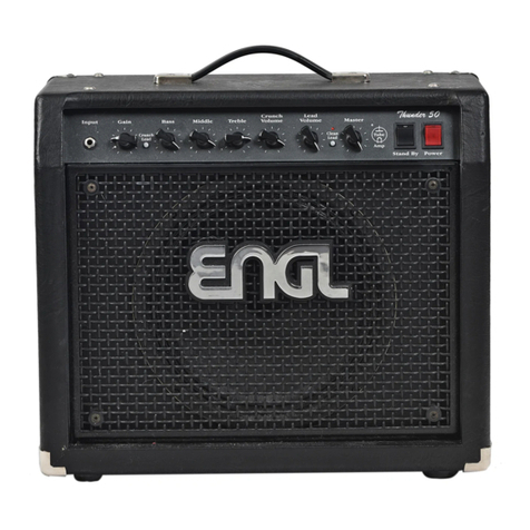
Engl Ironball SE E606SE User manual

E606SE
Ironball SE
Operator´s Manual

Input
Input (conventional 6,3mm / ¼“ TS) unbalanced input. Plug your guitar in ere using a s ielded
cord.
Clean Gain
Gain control for t e Clean c annel.
Lead Gain
Gain control for t e Lead c annel.
Bass
Bottom end voicing control of t e preamp´s passive EQ.
Middle
Mid-range voicing control of t e preamp´s passive EQ.
Treble
Upper range voicing control of t e preamp´s passive EQ.
Lead Presence
T is control defines t e Treble response in t e poweramp stage for t e Lead c annel.
Lead Volume
Volume control for t e Lead c annel (pre-FX Loop, influences t e send level). Use t is knob to dial in
t e desired balance of levels between t e Lead and Clean c annels.
Master
Master volume knob. Located post-FX Loop, it controls power amp output.

Store
T is pus button is to store a setting wit programmable features to a MIDI memory slot (generally
called a preset).
T is is ow it works:
1. Send a PC # message to t e amp.
2. Select t e desired c annel and functions for t e preset you want to create.
3. Press and old t e Store pus button for about 2 seconds to save t e preset to t e formerly
sent PC # until t e Store button LED is confirming t e process by flas ing 3 times s ort.
T e Store LED is also signalizing by flas ing permanently slow w en a c ange to a preset is
recognized. T e LED will stop signalizing c anges to a preset w ile t e Delay function is activated,
to avoid confusion.
M.V.B. - Master Volume Boost
T is feature increases t e master volume level, giving you instant access to two different volume
levels for different musical situations, for instance, one for r yt m parts and t e ot er for lead
lines.
Press t is pus switc to activate / deactivate t e M.V.B. function. T e red LED above t is pus
button lig ts up to indicate t at t e function is activated. T is feature can also be stored and
switc ed via MIDI.
Reverb
Press t is pus button to activate / deactivate t e Reverb function. T e red LED above t is pus
button lig ts up to indicate t at t e function is activated. T is feature can also be stored and
switc ed via MIDI.
Reverb Tails
Pus and old t e Reverb pus button for about 2 seconds until t e Reverb LED starts to flas .
T ree s ort flas es for Reverb Tails active, one long flas for Reverb Tails inactive. T is adjusted
status can be saved to a MIDI preset.
Dela
Press t is pus button to activate / deactivate t e Delay function. T e red LED above t is pus
button lig ts up to indicate t at t e function is activated. T is feature can also be stored and
switc ed via MIDI. T e Delay LED is signalizing t e Delay time, too.

Dela Tails
Pus and old t e Delay pus button for about 2 seconds until t e Delay LED starts to flas . T ree
s ort flas es for Delay Tails active, one long flas for Delay Tails inactive. T is adjusted status can
be saved to a MIDI preset.
Gain Boost
Press t is pus button to activate / deactivate t e Gain Boost function. T e red LED above t is pus
button lig ts up to indicate t at t e function activated. T is feature can also be stored and switc ed
via MIDI program c ange or controlled via t e respective ENGL Z4 (TRS) footswitc connected.
Clean/Lead Channel
Press t is pus button to toggle between t e Clean and t e Lead c annel. T e red LED above t is
pus button lig ts up to indicate t at t e Lead c annel is engaged. T is feature can also be stored
and switc ed via MIDI or controlled via t e respective ENGL Z4 (TRS) footswitc connected.
FX Loop
Press t is pus button to activate / deactivate t e FX Loop function. T e red LED above t is pus
button lig ts up to indicate t at t e function is activated. T is feature can also be stored and
switc ed via MIDI.
Noise Gate
Press t is pus button to activate / deactivate t e Noise Gate function and suppress excess noise
in t e Lead C annel wit or wit out t e Gain Boost function engaged. Control t e Noise Gate
t res old using t e Noise Gate knob on t e back of t e amp. T e red LED above t is pus button
lig ts up to indicate t at t e function is activated. T is feature can also be stored and switc ed via
MIDI program c ange.
Stand B
Use t is switc to silence t e amp w en you take a longer break. T e amp´s tubes stay nice and
toasty, and t e amp is ready to roll immediately w en you ramp it back up to full power. T e Stand
By switc is also well-suited for muting t e amp for brief breaks, for instance w en you are
switc ing guitars.
Power
Mains power on/off.
Please note: ensure t at t e Stand By switc is set to Stand By before you switc t e amp on. Let
t e tubes eat up for about 30 seconds before you activate t e power amp. T is procedure spares
t e tubes.

Dela Mix
T is control adjusts t e mix of dry signal to wet Delay signal and increases it´s intensity if you
rotate it clockwise.
Dela Time
T is control is to adjust t e Delay time. T e Delay LED s ows you t e delay time. T e Delay time can
also be tapped wit CC #54.
Dela Feedback
T is control sets t e Delay feedback level and increases t e number of repeats if you rotate it
clockwise.
Reverb
T is control adjusts mix of dry signal to wet Reverb signal and increases it´s intensity if you rotate
it clockwise.
Noise Gate
Use t is knob to set a t res old value (noise level) at w ic t e Noise Gate activates to suppress
t e signal. T e furt er you twist t e knob to t e rig t, t e ig er t e signal level at w ic t e Noise
Gate kicks in. If you set t e knob to t e 5 o‘clock position, t e Noise Gate reacts to extremely ig
noise levels, meaning t at t ere is not muc of a margin between t e guitar signal and background
noise.
IR Balanced Output – Pre/Post
T is button selects t e signal source for t e IR Balanced Output signal routed to t e XLR port.
W en t e button is not pus ed, t e line signal is tapped from t e preamp.
W en t e button is pus ed, t e line signal is tapped from t e power amp. T e Power Soak must set
to Speaker Off or a speaker load must be connected to t e Poweramp Output for t is option!

Power Range Selector
Use t is switc to activate t e Power Soak and select t e desired power level.
Full Power (approx. 20 Watts)
Mid Power (approx. 5 Watts)
Low Power (approx. 1 Watt)
Speaker Off (zero Watts)
W en activated, t e Power Soak´s resistors convert some or all of t e power amp´s output into
eat. So, make sure air can circulate freely around t e back of t e amp!
Main Suppl Connector (AC Power Inlet, IEC – C14 connector)
Plug t e mains cord in ere.
CAUTION! Make sure you use an intact mains line cord wit a grounded plug! Before you power t e
amp up, ensure t e voltage value (e.g. printed on t e Type Label or alongside t e mains port) is t e
same as t e current of t e local power supply or wall outlet. Please also eed t e guidelines set
fort in t e separately included pamp let, Instructions for t e Prevention of Fire, Electrical S ock
and Injury.
Mains Fuse Box
T e rear c amber contains t e mains fuse and t e front c amber a spare fuse.
NOTE: Ensure replacement fuses bear identical ratings (refer to t e tec nical data)!
CAUTION! Always make sure replacement fuses are of t e same type and ave t e same ratings as
t e original fuse! To t is end, please refer to t e fuse ratings s own on t e type panel.
Footswitch:
Clean/Lead and Gain Boost (conventional 6.3mm / ¼“ TRS). Use t is jack to connect a conventional
footswitc wit two switc ing functions, i.e. t e ENGL Z4 (2 x off/on – Single Pole Single T row or
SPST for s ort).
Tip: switc ing between t e Clean and t e Lead c annel.
Ring: switc ing Gain Boost on and off.
Phantom Power - ENGL Midi Footcontroller
T is selector activates a MIDI In port p antom power supply for powering an ENGL MIDI
footcontroller w en connected to t e amp. W en t e switc is pus ed in, power is routed to t e
MIDI In port´s pin 1 and pin 2. If you want to use a 3rd party MIDI footcontroller, be sure t at t e
switc is unpressed to avoid damaging t e amp or t e footcontroller.

T is feature is compatible wit t e ENGL Z9 (w ic we recommend to use wit t is amp) and t e
ENGL Z12 only.
MIDI In
T is 5-pin DIN port accepts data sent by a MIDI sender (ENGL Z9, ENGL Z12) or from or routed
t roug anot er MIDI device.
CAUTION: Before you connect any 3rd party MIDI footcontroller or effects device, always make sure
t at t e P antom Power switc is not engaded to avoid damaging t e connected device or t e amp.
MIDI Channel Auto Recognition
To assign t e MIDI c annel by w ic t e amp´s MIDI system will receive program c ange or specific
MIDI controller commands assigned to certain amp functions you need to enter t e MIDI C annel
Auto Recognition.
T is is ow it works:
1. T e Clean c annel must be engaged.
2. Press and old t e Noise Gate pus button for about 2 seconds until t e Noise Gate LED starts
flas ing fast.
3. Now send a PC (program c ange) or CC (control c ange) command on t e desired MIDI c annel
(e.g. PC #1 on MIDI c annel 1) to t e amp.
4. W en receiving data, it gets confirmed by t e store LED flas ing 3 times s ort.
5. Now t e amp is only listening to t e MIDI c annel (e.g. c annel 1) t at was formerly sent to t e
amp.
MIDI c annel OMNI mode (receiving data on all 16 c annels).
T is is ow it works:
1. T e Clean c annel must be engaged.
2. Press and old t e Noise Gate pus button for about 2 seconds until t e Noise Gate LED starts
flas ing fast.
3. Press and old t e store button for 2 seconds w ile t e Noise Gate LED is flas ing fast.
4. It gets confirmed by t e store button LED flas ing once long.
5. Now t e amp is receiving data from all c annels.
MIDI Controller Numbers
T e E606SE accepts CC # messages to control most of t e built-in functions, so t at MIDI
controllers #7 for example can be used to mute t e output signal. T is controller sends an Amp
Mute command w en assigned a value of 64 to 127. A value of 0 to 63 deactivates t e Amp Mute
command, t ereby unmuting t e amp and reactivating at its current Master volume setting. Most
controllers switc functions on (64 to 127) and off (value 0 to 63), w ile ot er controllers are using
specific values from 0 to 127. One of t ese is CC #35, w ic controls t e Reverb mix.

Anot er application is to tap t e Delay time via CC #54.
To tap t e delay time, t e time between two sent values wit CC #54 is measured. As an example,
t e assignment via an external MIDI foot controller can look like t is:
MIDI footcontroller “A” sends via pus ing button “X” (Momentary) w en pressed CC #54, value 127,
w en pressed again it sends again CC # 54, value 127. T e time between t e operations indicates
t e delay time.
T e following table lists amp functions and t eir assigned MIDI controller numbers.
USB
Connect t e amp to a computer to drag and drop your impulse response files.
Impulse responses will be stored in alp abetical sequence to t e slots 4 to 8.
T is is ow it works:
1. Connect your t e amp via a USB-B cable wit your computer.
2. Power t e amp up and wait until t e internal memory "ENGL" is recognized and ready.
3. Now you can drag and drop t e desired IR to t e amps internal memory.
4. W en done, [Safely Remove Hardware] and disconnect t e amp from t e computer.
5. “Reboot” t e amp (turn t e amp off, wait about 10 seconds and turn it on again).
6. Now t e loaded IR is ready to use.
Supported IR Files:
Files in mono up to a maximum size of 128kB / 96kHz (1 second @ 48kHz; 500ms @ 96kHz).
T e saved files are automatically assigned to t e IR selector switc (4 to 8) in alp anumeric order.
If t e files are outside of t ese specifications, t ey cannot be read and processed.

FX Loop
In t e signal pat , t e FX Loop is located post preamp and before t e power amp Master controls.
FX Loop Send
Connect t e FX Loop Send (output) to a signal processor´s input or an effect pedal´s input/return
jack using t e s ortest possible s ielded cord (conventional 6,3mm / ¼“ TS).
FX Loop Return
Connect t e FX Loop Return (input) to a signal processor´s output or an effect pedal´s
output/send jack using t e s ortest possible s ielded cord (conventional 6,3mm / ¼“ TS).
IR Selector
T is rotary switc allows you to select between eig t different IRs. T e first t ree are built-in ENGL
IRs:
1 - ENGL E212VHB (V30) Cabinet
2 - ENGL E412VSB (V30) Cabinet
3 - ENGL E412XXL (V30) Cabinet
T e selected IR can also be stored to t e a respective MIDI Preset. W en selecting an unused or
let´s say free slot, t e IR section is bypassed automatically.
Select and store an IR to a respecitve channel
Any IR can be simply assigned to t e Clean c annel and t e Lead c annel. T is works wit out aving
a MIDI footswitc and wit or wit out aving a TRS footswitc (Z4) connected.
1. Select a c annel (Clean or Lead).
2. Select t e IR you want to save to t e c annel.
Now t e setting is saved temporarily (for t is session) and will discarded by switc ing t e amp off.
You can assign one specific IR to t e Clean and anot er one to t e Lead c annel. W en you c ange
t e selection w ile t e respective C annel is active, t e new setting will be saved temporarily. To
save t e setting permanently you need to go on wit step 3.
3. Press and old t e Store pus button for about 2 seconds until t e Store LED begins to flas 3
times s ort to indicate t at t e selected IR is saved to t e c annel.
Please note, t at MIDI PC #1 will be overwritten by t is process.
Via MIDI you can select and save a specific IR to every preset. You just ave to select t e IR you
want to save to t e preset and follow t e standard Store procedure. Press and old t e Store pus
button for about 2 seconds until t e Store LED begins to flas 3 times s ort to indicate t at t e
selected IR is saved to t e c annel.
IR B pass
Pus and old t e FX Loop pus button for about 2 seconds until t e FX Loop LED starts to flas .
T ree s ort flas es for IR Bypass active, one long flas for IR Bypass inactive. T e IR Bypass will be
deactivated by selecting anot er IR as well. T e adjusted status will not be saved to a MIDI preset
but it is globally saved until you c ange it by olding and pressing t e FX Loop pus button for about
2 seconds again or moving t e IR Selector Switc . Powering t e amp off and on will discard t e
status to IR Bypass inactive as well.
T is feature is very useful, w en using t e E606SE Ironball Special Edition for a recording session
and you want to use an external IR Loader for example.
IR Balanced Output
Headp one Output
Connect a eadp one (3,5mm / 1/8” TRS) for easy monitoring or practice. W en selecting t e
Power Soak “Speaker Off” position you can practice wit out disturbing your neig bours.
CAUTION! When powering the amp up, upcoming noise can appear and damage hearing. Make
shure to remove the headphones while powering the device up.
Headp one Level
Adjusts t e level of t e Headp one output.
XLR – Ground
W en t is pus button is not pressed, t e ground is lifted. Pus t is switc w en you recognize
upcoming ground loop noise.
Poweramp Output
1. One 8 - 16 O m cabinet connected to t e left jack.
2. Two 16 O m cabinets connected to t e bot output jacks.
Important Note: We cannot stress enoug t e importance of proper impedance matc ing w en
connecting one or more cabinets to your amp. Impedance mismatc ing can damage t e poweramp!
Always c eck t e connected cabinet´s impedance to confirm it matc es t e amp´s output
impedance!

TECHNICAL DATA: ------------------------------------------------------------------------------
Output power approx. 20 Watts max
Input sensitivit
Input from -20 dB to approx. 0 dB max.
FX Return from -20 dB to approx. 0 dB max.
Output level
FX SEND from -20 dB to approx. 0 dB max.
XLR, Headp one approx. 0 dB at nominal power output
Power consumption approx. 80 Watts (95 VA) max.
Fuses
220 / 230 / 240 supply voltage 0,4 AT L (T: slow-blow)
100 / 115 / 120 supply voltage 0,8 AT L (T: slow-blow)
Power Tube Fuses 2 x 0,08 AM (M: medium-blow)
Important: Replace t ese wit fuses of t e same type and rating only!
Tubes
V1: ENGL ECC83 First Quality (FQ)
V2 / V3 / V4 ENGL ECC83 Selected (S)
V5 / V6 ENGL EL84 Hand-matc ed Duet
Dimension 34cm x 14cm x 22cm
Weight approx. 7kg

A FEW COMMENTS ON TUBE AMPLIFIERS-------------------------------------------------------
Be sure to read t is section before powering t e amp up!
T is amp´s input is extremely sensitive due to its ig gain factor. In combination wit in erent
microp onics of tubes, at certain settings t is can elicit powerful feedback from t e speakers –
even wit out a guitar being connected!
T is occurs primarily w en Crunc and Lead c annels (t at is, all c annels w ose preamp is easily
overdriven) are activated and t e following settings are dialed in:
-Gain and / or Lead Gain knob past t e 12 o´clock position
-Treble knob past t e 12 o´clock position
-Crunc / Lead Volume knob past t e 12 o´clock position
-Presence knob past t e 12 o´clock position
Avoid setting t e afore mentioned knobs to extreme positions (t at is, combinations in w ic
several of t ese knobs are set past t e 12 o´clock position). T is type of configuration can cause
considerable feedback t at could severely damage your earing and destroy speakers.
If you set t e Volume or Master knobs to ig er volume levels, always make sure to back off
amplification levels to prevent feedback by turning t e Lead c annel Gain knobs down. T e same
applies to t ese c annel´s Treble and Presence knob settings.
Before you power t e amp up, take a moment to c eck out t e control panel and make sure t at
t ese knobs are not set to any configuration similar to t e one described above!
A FEW WORDS ON BACKGROUND NOISE IN TUBE AMPLIFIERS
You may ear slig t background noise rig t after you power a tube amp up or even w ile you are
operating. It manifests as intermittent issing or sizzling, crackling, or popping noises. Caused by
tubes, t is type of noise may even occur wit brand new tubes.
T e noise is particularly noticeable in ig -gain Lead c annels. T is is because t e Lead
c annels provide a very ig gain factor, amplifying noise along wit t e usable guitar signal.
It is not necessary to swap tubes if you encounter t is kind of noise every now and t en, t oug you
may consider replacing tubes if it becomes a constant companion.

TROUBLESHOOTING-----------------------------------------------------------------------------
The output volume fluctuates or drops:
-Take all effect devices (infront of t e preamp and FX Loop) out of t e signal c ain.
-C eck all used cables.
-C eck t e used guitar or use anot er guitar.
-Use a patc or guitar cable to patc e FX Send wit t e FX Return jack.
-Try using an external and functional power amp wit t e preamp of t e amp (FX Send
connected to an external power amp) to exclude a problem wit t e amp´s internal
preamp.
-Try using an external and functional preamp wit t e poweramp of t e amp (FX Return
connected to an external preamp) to exclude a problem wit t e amp´s poweramp.
The amp is not providing a proper output signal / no or low sound is emanating from the
speaker:
-Is at least one speaker connected to t e speaker outputs?
-Is t e power amp activated ( Stand By switc to ON)?
-Are all cords (guitar, effects and speaker) connected properly and are t ey functional?
-Take all effect devices (before t e preamp, FX Loop) out of t e signal c ain.
-Is t e Noise Gate activated? (Relevant only, if t e amplifier is equipped wit a Noise
Gate).
-Are t e Master knob and t e Gain and Volume knobs set to a value ig er t an 0? If any
of t ese knobs is set to zero, no signal is routed to t e amp´s output.
The speaker is emitting humming noises:
-T e amp and mains ground are not connected properly or are altoge ter disconnected.
Please ave t is c ecked by a tec nician.
-C ords connected to t e input or FX Loop may not be s ielded properly. Replace t em to
c eck if t is is indeed t e case.
-T e amp or speaker cords may be picking up interferrence from powerful magnetic
fields (i.e., of nearby power transformers or electrical motors). Reposition t e amp and
connector cables.
-T e amp or speaker cords may be picking up radio signals. For example, from activated
mobile p ones or powerful local transmitting stations nearby. Switc off mobile p ones
w ile troubles ooting noise problems.

Please contact us via e-mail: [email protected] before shipping a product to us.
T e more precise t e error description is, t e better our service team can elp you. It is best to
send us a p oto of t e control settings and a video recording. A detailed description of t e error
also elps us to isolate and locate t e problem faster.
- W ic c annels are affected?
- W ic functions are activated?
- In w ic knob positions does t e problem occur?
- Are you using effects devices before t e input or in t e FX-Loop?
- Does t e problem occur in standby mode (noise issues)?
- W at equipment is used in detail?
Packaging
Please make sure to use suitable packaging to ensure undamaged transport (use original PKG). To
unfold t e full protective function of t e packaging, t e outer packaging, t e device and t e inner
packaging must form a single unit. T is is t e only way to ensure t at t e device survives t e
transport route undamaged.
Please c eck used packaging for tears, signs of compression, pressure marks, perforations or
ot er damage before use. Please do not use damaged packaging. Note t at a flig t case is not a
suitable s ipping packaging and is t erefore not accepted. Please never pack devices toget er (e.g.
Z4 Footswitc + E633 Head), but send t em separately. As it is our responsibility to use suitable
s ipping packaging for return s ipping, we reserve t e rig t to use a new original packaging if
necessary and must also invoice it.
Original Packaging
Our original packaging consists of particularly t ick cardboard material and is equipped wit
special, custom-made molded foam parts for eac model. This packaging can be used several
times - do not throw it awa !

Using the ENGL Z9 or Z12 to control the amp.
T is is ow it works:
1. Connect your ENGL Z9 or Z12 to t e amp by a 5-pin MIDI cable.
>> To use the phantom power option ou need to use a 5-pin MIDI cable.
2. Activate t e p antom power switc (backside of t e amp).
>> Deactivate this function if ou are using a MIDI footswitch from another manufacturer.
3. Send a PC # message by pressing a switc on t e Z9 or Z12.
4. Activate all desired functions on t e map you want to add to your preset.
5. Press and old t e Store pus button for about 2 seconds to save t e preset to t e formerly
sent PC # until t e Store button LED is confirming t e process by flas ing 3 times s ort.
6. T e preset is saved to t e assigned footswitc .
Whilst the information contained herein is correct at the time of publication, due to our
polic of constant improvement and development, ENGL AMPLIFICATION reserves the right to
alter specifications without prior notice.
E606SE-OM-2-05/21

www.engl-amps.com
Table of contents
Other Engl Amplifier manuals

Engl
Engl E530 User manual

Engl
Engl Savage Special Edition User manual

Engl
Engl Rockmaster 20 E307 User manual

Engl
Engl Screamer 50 II Combo E330II User manual

Engl
Engl TUBE TONER E430 User manual

Engl
Engl E412 Manual

Engl
Engl e840 User manual

Engl
Engl E610II User manual

Engl
Engl TUBE PREAMP 570 User manual

Engl
Engl True Poweramp 830 User manual

Engl
Engl Tube Preamp 530 User manual

Engl
Engl TUBE POWERAMP 810 User manual

Engl
Engl E633 User manual

Engl
Engl Screamer 50 User manual

Engl
Engl Midi Tube Preamp 580 User manual

Engl
Engl Squeeze 60 User manual

Engl
Engl 520 User manual

Engl
Engl Road User manual

Engl
Engl Full Tube Guitar Amplifier User manual

Engl
Engl Savage 60 User manual