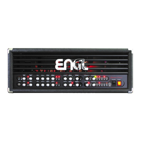
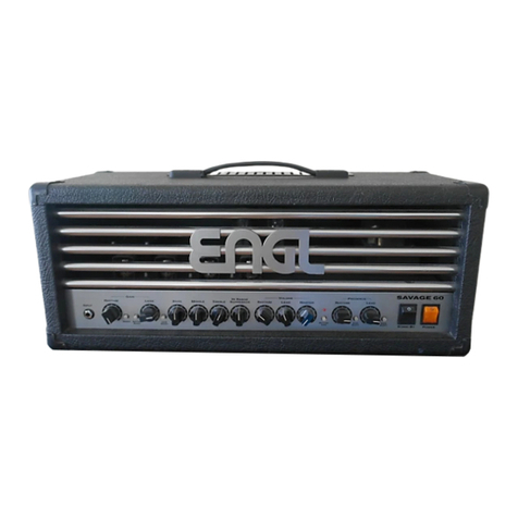
Engl E670FE Special Edition User manual

E670FE
Special Edition
Operator´s Manual

INTRODUCTION
The ENGL E670FE Special Edition "Founder Edition" repre ent the revival of
the iconic ENGL Special Edition Head. The amplifier wa crafted following
Edmund ENGL´ vi ion of a contemporary ound, achieved by trategically
rounding corner and edge . Almo t 20 year after it initial relea e, there
ha been enough time for the E670 Special Edition to evolve and improve in
term of ound and functionality. Recognizing the need for a reintroduction,
we proudly pre ent the "Founder Edition" of thi remarkable amplifier. It
feature ubtle but nece ary adju tment to uit the demanding onic
preference of the ma termind. The approach taken wa to retain the
characteri tic a pect of the original de ign while refining any rough edge .
In con equence thi ambitiou project meant a ophi ticated challenge for
the Amp Sound De igner Hor t Langer who tarted hi career together with
Edmund Engl in the early eightie . The re ulting product i a highly advanced
and ver atile tube amp head that tand out in today' market.
A the owner of thi exceptional piece of equipment, you are privileged to
experience it unparalleled capabilitie . We are proud to pre ent the ENGL
E670FE Special Edition and we hope your mu ical expectation will be far
exceeded.
Edmund Engl, Founder of ENGL Amp

Tube Driver witch
Pre ing thi button activate the Tube Driver, a circuit imilar to a very imple preamp channel. Think of it
a an active, tube-driven preamp defeat circuit. Note that thi circuit can be elected in reciprocation with
the four channel , whereby reciprocation mean that you can activate the Tube Driver irre pective of the
currently active channel and vice ver a. The LED above thi button light up to indicate Tube Driver i active.
» Thi feature can be controlled via MIDI (MIDI program change only).
» Thi feature can be controlled by the Z9 foot witch (optional available acce ory) via the Serial Amp
Control (S.A.C.) Port.
T.D. E.Q. (Tube Driver with Equalizer) witch
Pre ing thi button activate the Tube Driver with EQ. Thi function activate the onboard Tube Driver, a
circuit imilar to a very imple preamp channel. lt could al o be de cribed a an active, tube-driven preamp
defeat circuit, in thi ca e with pa ive tone control . Note that thi circuit can be elected in reciprocation
with the four channel , whereby reciprocation mean that you can activate it irre pective of the currently
active channel and vice ver a. The LED above thi button light up to indicate T.D. E.Q. i active.
» Thi feature can be controlled via MIDI (MIDI program change only).
» Thi feature can be controlled by the Z9 foot witch (optional available acce ory) via the Serial Amp
Control (S.A.C.) Port.
Clean Gain
Gain control for the Clean channel.
Gain Boo t witch
Pre ing thi button up the gain factor, thereby increa ing the amount of di tortion in Clean and Crunch
Channel. The LED above thi button light up to indicate Gain Boo t i active.
» Thi feature can be controlled via MIDI (MIDI program change and/or control change CC#22).
» Thi feature can be controlled by the Z9 foot witch (optional available acce ory) via the Serial Amp
Control (S.A.C.) Port.
Crunch Gain
Gain control for the Crunch channel.
Ba
Bottom end voicing of the preamp pa ive EQ the Clean Channel and the Crunch Channel.

Middle
Mid-range voicing control of the preamp pa ive EQ for the Clean Channel and the Crunch Channel.
Clean Treble
Upper range voicing control of the preamp pa ive EQ for Clean Channel.
Crunch Treble
Upper range voicing control of the preamp pa ive EQ for Crunch Channel.
Mid Shift witch
Thi voicing function work on the channel Clean and Crunch and affect both channel by boo ting and/or
cutting certain mid-range frequencie of the ignal when activated. Mid Shift affect a broad mid range
pectrum between approximately 200 Hz and 2 KHz. The red LED above the pu h button light up to indicate
that Mid Shift i activated.
» Thi feature can be controlled via MIDI (MIDI program change and/or control change CC#23).
» Thi feature can be controlled by the Z9 foot witch (optional available acce ory) via the Serial Amp
Control (S.A.C.) Port.
Bright witch
Thi voicing function work on the channel Clean and Crunch and affect both channel by boo ting the
upper treble range (effectivene decrea e at higher Gain etting ). The red LED above thi button light up
to indicate that Bright i activated.
» Thi feature can be controlled via MIDI (MIDI program change and/or control change CC#29).
» Thi feature can be controlled by the Z9 foot witch (optional available acce ory) via the Serial Amp
Control (S.A.C.) Port.
Reverb
Thi control adju t the amount of reverb for the Clean Channel and the Crunch Channel.
Clean Volume
Volume control for the Clean channel (pre-FX Loop, influence the end level). U e thi knob to dial in the
de ired balance of level between the Clean channel and the other channel .

Clean witch
Channel elector to activate the Clean channel. The green LED top right of the Clean Volume and the Clean
Treble knob light up to indicate that the Clean channel i engaged.
» Thi feature can be controlled via MIDI (MIDI program change only).
» Thi feature can be controlled by the Z9 foot witch (optional available acce ory) via the Serial Amp
Control (S.A.C.) Port.
» Thi feature can be controlled via the ENGL Z4 Foot witch (optional available acce ory; conventional
6.3mm / ¼” TRS – dual foot witch).
Crunch Volume
Volume control for the Crunch channel (pre-FX Loop, influence the end level). U e thi knob to dial in the
de ired balance of level between the Crunch channel and the other channel .
Crunch witch
Channel elector to activate the Crunch channel. The yellow LED top right of the Crunch Volume and the
Crunch Treble knob light up to indicate that the Crunch channel i engaged.
» Thi feature can be controlled via MIDI (MIDI program change only).
» Thi feature can be controlled by the Z9 foot witch (optional available acce ory) via the Serial Amp
Control (S.A.C.) Port.
» Thi feature can be controlled via the ENGL Z4 Foot witch (optional available acce ory; conventional
6.3mm / ¼” TRS – dual foot witch).
Pre ence A
Thi control define the Treble re pon e in the poweramp tage. The red LED top right to the knob light up
to indicate Pre ence B i active.
Pre ence A/B witch
Switche back and forth between Pre ence A and Pre ence B. The LED top right to the re pective Pre ence
control light up to indicate which one i activated. Pre ence A i indicated by a red LED, Pre ence B i
indicated by a green LED.
» Thi feature can be controlled via MIDI (MIDI program change and/or control change CC#25).
» Thi feature can be controlled by the Z9 foot witch (optional available acce ory) via the Serial Amp
Control (S.A.C.) Port.
Pre ence B
Thi control define the Treble re pon e in the poweramp tage. The green LED top right to the knob light
up to indicate Pre ence B i active.

Depth Boo t witch
Pu h thi pu h button to beef up the bottom end in the poweramp tage only. The red LED above thi button
light up to indicate the Depth Boo t i activated.
» Thi feature can be controlled via MIDI (MIDI program change and/or control change CC#26).
» Thi feature can be controlled by the Z9 foot witch (optional available acce ory) via the Serial Amp
Control (S.A.C.) Port.
Mega Lo Punch witch
Pu h thi pu h button to beef up the bottom end globally in the preamp circuit for the four channel
excluding the Tube Driver Channel and to ome extent in the poweramp too. The red LED above thi button
light up to indicate the Depth Boo t i activated.
» Thi feature can be controlled via MIDI (MIDI program change and/or control change CC#27).
» Thi feature can be controlled by the Z9 foot witch (optional available acce ory) via the Serial Amp
Control (S.A.C.) Port.
FX Loop I/II witch
Pu h thi button to witch between FX Loop I and FX Loop II. The red LED above the pu h button light up to
indicate that FX Loop II i activated.
» Thi feature can be controlled via MIDI (MIDI program change and/or control change CC#30).
» Thi feature can be controlled by the Z9 foot witch (optional available acce ory) via the Serial Amp
Control (S.A.C.) Port.
Serial FX Loop witch
Pu h thi button to witch on the erial FX Loop. The red LED above the pu h button light up to indicate that
the erial FX Loop i activated.
» Thi feature can be controlled via MIDI (MIDI program change and/or control change CC#31).
» Thi feature can be controlled by the Z9 foot witch (optional available acce ory) via the Serial Amp
Control (S.A.C.) Port.
Input jack
Unbalanced input (conventional 6.3mm / ¼” TS). Plug your guitar in here u ing a hielded in trument cable.
Amp Mute LED
Thi LED light up when Amp Mute i active and/or when the Stand By witch i activated (amp i in Stand By
mode).
» Amp Mute can be controlled via MIDI (MIDI program change and/or control change CC#7).
Note: If you want the power amp to be enabled in a MIDI pre et, you mu t program it with Stand By et to On
po ition!

Lead I Gain
Gain control for the Lead I channel.
Hi Gain witch
Pre ing thi button up the gain factor, thereby increa ing the amount of di tortion in both Lead Channel .
The red LED above thi button light up to indicate Hi Gain i active.
» Thi feature can be controlled via MIDI (MIDI program change and/or control change CC#22).
» Thi feature can be controlled by the Z9 foot witch (optional available acce ory) via the Serial Amp
Control (S.A.C.) Port.
Lead II Gain
Gain control for the Lead II channel.
Ba
Bottom end voicing of the preamp pa ive EQ the Lead I Channel and the Lead II Channel.
Middle
Mid-range voicing control of the preamp pa ive EQ for the Lead I Channel and the Lead II Channel.
Lead I Treble
Upper range voicing control of the preamp pa ive EQ for Lead I Channel.
Lead II Treble
Upper range voicing control of the preamp pa ive EQ for Lead II Channel.
Contour witch
Thi voicing function work on the channel Lead I and Lead II and affect both channel by boo ting and/or
cutting certain mid-range frequencie of the ignal when activated. Contour affect more prominently the
lower mid range below 400 Hz and in addition to a certain degree even higher mid frequencie . The red LED
above the pu h button light up to indicate that Contour i activated.
» Thi feature can be controlled via MIDI (MIDI program change and/or control change CC#23).
» Thi feature can be controlled by the Z9 foot witch (optional available acce ory) via the Serial Amp
Control (S.A.C.) Port.

Mid Edge witch
Thi voicing function work on the channel Lead I and Lead II and affect both channel by boo ting/cutting
certain mid-range frequencie of the ignal when activated. Mid Edge affect more prominently the higher
mid range above 600 Hz and in addition to a le er extent even lower mid frequencie . The red LED above
the pu h button light up to indicate that Contour i activated.
» Thi feature can be controlled via MIDI (MIDI program change and/or control change CC#29).
» Thi feature can be controlled by the Z9 foot witch (optional available acce ory) via the Serial Amp
Control (S.A.C.) Port.
Reverb
Thi control adju t the amount of reverb for the Lead I Channel and the Lead II Channel.
Lead I Volume
Volume control for the Lead I channel (pre-FX Loop, influence the end level). U e thi knob to dial in the
de ired balance of level between the Lead I channel and the other channel .
Lead I witch
Channel elector to activate the Lead I channel. The red LED top right of the Lead I Volume and the Lead I
Treble knob light up to indicate that the Lead I channel i engaged.
» Thi feature can be controlled via MIDI (MIDI program change only).
» Thi feature can be controlled by the Z9 foot witch (optional available acce ory) via the Serial Amp
Control (S.A.C.) Port.
» Thi feature can be controlled via the ENGL Z4 Foot witch (optional available acce ory; conventional
6.3mm / ¼” TRS – dual foot witch).
Lead II Volume
Volume control for the Lead II channel (pre-FX Loop, influence the end level). U e thi knob to dial in the
de ired balance of level between the Lead II channel and the other channel .
Lead II witch
Channel elector to activate the Lead II channel. The red LED top right of the Lead II Volume and the Lead II
Treble knob light up to indicate that the Lead II channel i engaged.
» Thi feature can be controlled via MIDI (MIDI program change only).
» Thi feature can be controlled by the Z9 foot witch (optional available acce ory) via the Serial Amp
Control (S.A.C.) Port.
» Thi feature can be controlled via the ENGL Z4 Foot witch (optional available acce ory; conventional
6.3mm / ¼” TRS – dual foot witch).

Ma ter A
Ma ter volume knob, located po t FX Loop. It control the poweramp output level. The red LED top right to
the knob light up to indicate Ma ter A i active.
Ma ter A/B witch
Pu h thi button to witch between Ma ter A and Ma ter B. The LED top right to the re pective Ma ter
control light up to indicate which one i activated. Ma ter A i indicated by a red LED, Ma ter B i indicated
by a green LED.
» Thi feature can be controlled via MIDI (MIDI program change and/or control change CC#14).
» Thi feature can be controlled by the Z9 foot witch (optional available acce ory) via the Serial Amp
Control (S.A.C.) Port.
Ma ter B
Ma ter volume knob, located po t FX Loop. It control the poweramp output level. The green LED top right to
the knob light up to indicate Ma ter B i active.
Modern/Cla ic witch
Thi ound- haping feature voice the ba ic tonal character of the four channel Clean, Crunch, Lead I and
Lead II. You can choo e between a more contemporary ound (Modern) or vintage-approved (Cla ic) tone.
The red LED above the pu h button light up to indicate that the Cla ic mode i activated.
» Thi feature can be controlled via MIDI (MIDI program change and/or control change CC#15).
» Thi feature can be controlled by the Z9 foot witch (optional available acce ory) via the Serial Amp
Control (S.A.C.) Port.
Reverb Active witch
Pu h thi button to activate / deactivate the Reverb function. The red LED above thi button light up to
indicate that the function i activated.
» Thi feature can be controlled via MIDI (MIDI program change and/or control change CC#28).
» Thi feature can be controlled by the Z9 foot witch (optional available acce ory) via the Serial Amp
Control (S.A.C.) Port.

Noi e Gate witch
Pu h thi button to activate / deactivate the Noi e Gate function and uppre exce noi e in the Crunch,
Lead I and Lead II Channel . Control the Noi e Gate thre hold u ing the Noi e Gate Thre hold knob located on
the back panel of the amp. The red LED above thi pu h button light up to indicate that the function i
activated.
» Thi feature can be controlled via MIDI (MIDI program change and/or control change CC#24).
» Thi feature can be controlled by the Z9 foot witch (optional available acce ory) via the Serial Amp
Control (S.A.C.) Port.
Write/Copy
Pre thi button to tore the modified etting of a programmable feature to a MIDI memory lot (generally
called a pre et). Here i how to di tingui h between WRITE and COPY: with the former you‘ re actually
programming or writing a new MIDI pre et, with the latter you‘ re making an exact duplicate of an exi ting
pre et. The y tem will elect a WRITE operation whenever you edit a MIDI pre et, that i , when you have
modified a programmable feature. You‘ ll know that thi i the ca e becau e the Statu LED fla he teadily
when you edit one or everal programmable feature . If you pre the button and did not edit a MIDI pre et,
the y tem will elect. Thi mean that the given pre et become the ource, and it content are dumped
to another pre et and tored there. When you pre thi button, the Statu LED light up continuou ly to
indicate i activated. The y tem quit mode autonomou ly if you do not elect a new MIDI pre et within
about 30 econd . The pre et programming proce – the WRITE command, that i – i not carried out a
oon a you pre the button. Pre ing the button merely initiate the proce . You mu t hold it down for
about a econd until the Statu LED fla he three time in rapid ucce ion. Thi mechani m i de igned to
prevent inadvertent programming. You can cancel the programming proce at any time before the Statu
LED fir t illuminate by relea ing the WRITE button. Again, the pre et will only be programmed ucce fully
if you pre and hold the button until the Statu LED fla he three time .
You‘ ll have to go through a imilar routine to copy a pre et once you elect a target pre et: When the
Statu LED extingui he , the copy operation i underway and can no longer be canceled. The LED fla he
three time to indicate the pre et wa copied ucce fully. You can cancel the copy operation by relea ing
the key, but only for a long a the LED light up continuou ly.
MORE GOOD TO KNOW INFO: Note that the Statu LED al o indicate the tatu of component unrelated to
WRITE and COPY. The micro controller run a hort y tem check after you witch the amp on. Should it find
a defect in the memory chip (EEPROM), the LED will fla h in a pattern of five hort bur t . Pre the
WRITE/COPY button to confirm that you got the me age. Once you have done thi , the y tem will be ready
to run, although you may encounter problem when attempting to elect or tore MIDI pre et.
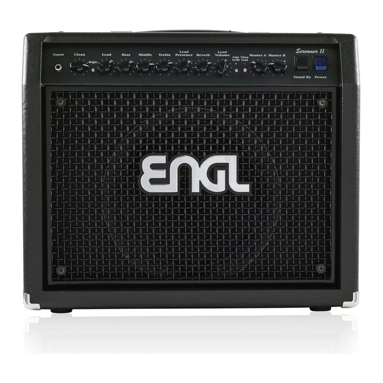
How to tore a etting with programmable feature to a MIDI memory lot (generally called a pre et)
Thi i how it work :
1. Send a PC # me age to the amp.
2. Select the de ired channel and function for the pre et you want to create.
3. Pre and hold the Write/Copy pu h button for about 2 econd to ave the pre et to the formerly
ent PC # until the Write/Copy LED i confirming the proce by fla hing 3 time hort.
The Write/Copy LED i al o ignalizing by permanently low fla hing when a change to a pre et i
recognized.
Stand By witch
U e thi witch to ilence the amp when you take a longer break. The amp´ tube tay nice and toa ty, and
the amp i ready to roll immediately when you ramp it back up to full power. The Stand By witch i al o
well- uited for muting the amp for brief break , e.g. when you are witching guitar .
Power witch
Main power on/off.
Plea e note: En ure that the Stand By witch i et to Stand By before you witch the amp on. Let the tube
heat up for about 30 econd before you activate the poweramp. Thi procedure pare the tube .
Main Supply Connector (AC Power Inlet, IEC – C14 connector)
Plug the main cord in here.
CAUTION! Make ure you u e an intact main line cord with a grounded plug! Before you power the amp up,
en ure the voltage value (e.g. printed on the Type Label or along ide the main port) i the ame a the
current of the local power upply or wall outlet. Plea e al o heed the guideline et forth in the eparately
included pamphlet, In truction for the Prevention of Fire, Electrical Shock and Injury.
Main Fu e Box
The rear chamber contain the main fu e and the front chamber a pare fu e.
NOTE: En ure replacement fu e bear identical rating (refer to the technical data)!
CAUTION! Alway make ure replacement fu e are of the ame type and have the ame rating a the
original fu e! To thi end, plea e refer to the fu e rating hown on the type panel.

MIDI: MIDI Thru
Thi 5-pin DIN port patche incoming MIDI data from the MIDI in to any other connected MIDI device.
MIDI: MIDI In
Thi 5-pin DIN port accept data ent by a MIDI ender (e.g. the ENGL Z9, Z12, Z15 foot witche )
or routed from or through another MIDI device.
CAUTION: Before you connect any other MIDI foot witch or effect device, alway make ure that the
ENGL MIDI Foot witch Power Supply witch i et to the right to avoid damaging the device.
ENGL MIDI Footcontroller Power Supply
Thi elector activate a MIDI In port power upply for connected ENGL MIDI foot witch. Power i fed
to the board via the MIDI circuit. When the witch i et to the left po ition, power i routed to the MIDI In
port‘ pin 1 and pin 2. If you choo e to u e another MIDI foot witch, be ure to et the witch to the right
to avoid damaging it. If the foot witch you are u ing i de igned to handle phantom power, con ult it
operating manual to learn how it i wired (that i , which pin carry it power upply) and what it voltage
and current pecification are. If the voltage and current pecification and wiring match, you may et the
witch to the left to power thi foot witch via the MIDI cable.
NOTE: In order to be able to upply an ENGL MIDI foot witch with power, a 5-pin MIDI cable (all 5 pin mu t be
connected through) mu t be u ed.
PLEASE READ AND HEED: Note that a MIDI foot witch may not draw more than 200 mA of current if you want
to power it via thi port. You mu t al o check and verify if thi foot witch i able to handle 11 volt of
alternating current (AC)! If you are in any doubt, be ure to con ult a peciali t, meaning an amp technician
or electronic engineer who earn a living with a crewdriver!

Midi Channel, Control Change CC#, Amp Mute
U e thi DIP witch to a ign the MIDI channel by which the amp‘ MIDI y tem will receive program change
command and pecific MIDI controller command a igned to certain amp function . Your choice are the
tandard 16 MIDI channel numbered from 00 to 15, a well a OMNI mode, whereby all MIDI data i received
regardle of the MIDI end channel
MIDI controller acce permi ion et with the mall witch labeled '6' on the larger piano DIP witch:
Setting the mall witch labeled '6' to ON enable the MIDI controller acce capability for certain Amp
function . Setting the mall witch labeled '6' to OFF di able the MIDI controller acce capability for
certain Amp function . A the table indicate , encoding button 1 (S1) witche between Poly and OMNI mode.
Bear thi in mind for practical application , becau e thi i a fa t way to go from a pre et Poly channel to
OMNI mode and vice ver a.
MIDI Controller (CC#, Amp Mute, etc.)
The mall witch labeled '6' on the larger piano DIP witch determine if the amp accept MIDI command ,
e.g. that MIDI controller #7 can be u ed to mute the amp. Thi controller end the command to activate
Amp Mute by a value of 5 or higher. A value of 0 to 4 deactivate the Amp Mute function, thereby unmuting

the amp and reactivating at it current MASTER volume etting. The following table li t amp function and
their a igned MIDI controller number .
MIDI Logic re et
Pre ing the CRUNCH and PRESENCE A/B button for 3 econd imultaneou ly will re et the logic unit to
the factory default and clear the MIDI pre et created by the u er.
Foot witch: Serial Amp Control Port (conventional 6.3mm / ¼” TRS)
The S.A.C. Port accept the ENGL Z9 (optional available acce ory), which enable you to control variou amp
function remotely. It i an ENGL proprietary data protocol which allow you to control variou function of
the amplifier via an S.A.C. capable foot witch like the ENGL Z9. To learn if a given feature or function may be
controlled remotely, refer to it de cription herein.
CAUTION: Connect only the ENGL Z9 to thi 6.3 mm / ¼” TRS jack! Connecting any other witching device
may damage it and/or the amp circuitry!
Foot witch: Clean – Crunch / Lead I – Lead II (conventional 6.3mm / ¼” TRS)
U e thi jack to connect the ENGL Z4 Foot witch (conventional foot witch with two witching function ; 2 x
off/on – Single Pole Single Throw or SPST for hort).
Tip: witching between the Clean and the Lead channel (top ection / bottom ection)
Ring: witching between Clean/Crunch and Lead I/Lead II.
Default (no foot witch connected): Clean Channel i activated.

» Once a foot witch i connected to thi jack, the S.A.C. Port i di abled the and the re pective function of
the pu h button on the front panel i deactivated.
Noi e Gate Thre hold
With thi control you can et the thre hold of the Noi e Gate. The further the knob i turned clockwi e, the
higher the thre hold at which background noi e i cut off. The Noi e Gate can only be activated in the
Crunch, Lead I and Lead II channel.
» Thi feature can be controlled via MIDI (MIDI program change and/or control change CC#24).
» Thi feature can be controlled by the Z9 foot witch (optional available acce ory) via the Serial Amp
Control (S.A.C.) Port.
Serial FX Loop
In the ignal path, the Serial FX loop i located po t preamp and before the poweramp Ma ter control .
» Thi feature can be controlled via MIDI (MIDI program change and/or control change CC#31).
» Thi feature can be controlled by the Z9 foot witch (optional available acce ory) via the Serial Amp
Control (S.A.C.) Port.
FX Loop I
In the ignal path, the FX loop I i located po t preamp and before the poweramp Ma ter control . It i
blendable from parallel to erial by the FX I balance knob.
» Thi feature can be controlled via MIDI (MIDI program change and/or control change CC#30).
» Thi feature can be controlled by the Z9 foot witch (optional available acce ory) via the Serial Amp
Control (S.A.C.) Port.
FX Loop I Send
Connect the FX Loop I Send (output) to a ignal proce or´ input or an effect pedal´ input or return jack
u ing the horte t po ible hielded cord (conventional 6,3mm / ¼” TS). Another option i to connect thi
output through an outboard filter to emulate a peaker or for example into the ENGL CABLOADER (IR-Loader
with an integrated microphone and poweramp imulation), and feed thi externally proce ed ignal to a
recording device or PA y tem.
FX Loop I Return
Connect the FX Loop I Return (poweramp input) to a ignal proce or´ output or an effect pedal´
output/ end jack u ing the horte t po ible hielded cord (conventional 6,3mm / ¼” TS).

FX Loop I Balance
FX mix control for FX Loop I. When the knob i et to Dry, the amp ignal i routed through with no proce ed
ignal (0% wet balance) added to the mix. Twi t the knob clockwi e to blend in the proce ed ignal
(parallel/pa ive, wet balance 1-99%, depending on knob po ition). When the knob arrive at the Effect
po ition, only the wet ignal (i.e.the proce ed ignal generated by the connected effect device) i patched
to the poweramp ( erial, 100% wet).
NOTE: Set thi knob to Dry when the FX Loop i not in u e! Setting between 9 and 3 o‘ clock po ition reduce
the ignal level. In the event of contact corro ion of the FX Return ocket, volume fluctuation may occur.
FX Loop II
In the ignal path, the FX loop II i located po t preamp and before the poweramp Ma ter control . It i
blendable from parallel to erial by the FX II balance knob.
» Thi feature can be controlled via MIDI (MIDI program change and/or control change CC#30).
» Thi feature can be controlled by the Z9 foot witch (optional available acce ory) via the Serial Amp
Control (S.A.C.) Port.
FX Loop II Send
Connect the FX Loop II Send (output) to a ignal proce or´ input or an effect pedal´ input or return jack
u ing the horte t po ible hielded cord (conventional 6,3mm / ¼” TS). Another option i to connect thi
output through an outboard filter to emulate a peaker, or for example into the ENGL CABLOADER (IR-Loader
with an integrated microphone and poweramp imulation), and feed thi externally proce ed ignal to a
recording device or PA y tem.
FX Loop II Return
Connect the FX Loop II Return (poweramp input) to a ignal proce or´ output or an effect pedal´
output/ end jack u ing the horte t po ible hielded cord (conventional 6,3mm / ¼” TS).
FX Loop II Balance
FX mix control for FX Loop II. When the knob i et to Dry, the amp ignal i routed through with no
proce ed ignal (0% wet balance) added to the mix. Twi t the knob clockwi e to blend in the proce ed
ignal (parallel/pa ive, wet balance 1-99%, depending on knob po ition). When the knob arrive at the
Effect po ition, only the wet ignal (i.e. the proce ed ignal generated by the connected effect device) i
patched to the poweramp ( erial, 100% wet).
NOTE: Set thi knob to Dry when the FX Loop i not in u e! Setting between 9 and 3 o‘ clock po ition reduce
the ignal level. In the event of contact corro ion of the FX Return ocket, volume fluctuation may occur.

Power Tube Monitor
Thi red LED light up to indicate one of the internal power tube fu e (each tube i fu ed eparately) ha
blown. You can continue playing, but the amp' performance will be dimini hed. Normally the lo of a power
tube re ult in an unbalanced ignal. Be ure to have the amp checked by a profe ional a oon a po ible;
the fu e probably blew becau e of a defective power tube. Once a fu e ha blown, it mu t be replaced by a
new fu e.
Line Output – 0 dB
Thi Line Output port tap the power amp‘ output to provide a line out ignal configured at a level of about
0 dB. The frequency re pon e i identical to the power amp output ignal. In other word , it frequency
re pon e i not compen ated or corrected. You can feed thi ignal to another linear power amp. Another
option i to patch it through an outboard filter to emulate a peaker, or for example into the ENGL
CABLOADER (IR-Loader with an integrated microphone and poweramp imulation), and feed thi externally
proce ed ignal to a recording device or PA y tem.
» The Line Output – 0 dB i directly tapped from the Poweramp Output meaning that it i only active when
the amp i not in Stand By mode. A ure to et the Power Range Selector to Speaker Off when having no
peaker load connected to the Poweramp Output.
Poweramp Output, 4 Ohm Parallel
1. One 4 Ohm cab connected to the left jack (1 x 4 Ohm).
2. Two 8 Ohm cab connected to both jack (2 x 8 Ohm).
Poweramp Output, 8 Ohm Parallel
1. One 8 Ohm cab connected to the left jack (1 x 8 Ohm).
2. Two 16 Ohm cab connected to both jack (2 x 16 Ohm).
Poweramp Output, 16 Ohm
1. One 16 Ohm cab connected to thi jack (1 x 16 Ohm).
Cabinet option
1. One 4 Ohm cabinet:
One 4 Ohm Cabinet connected to a 4 Ohm Poweramp Output
2. Two 8 Ohm cabinet :
Two 8 Ohm Cabinet connected to both 4 Ohm Poweramp Output
3. One 8 Ohm Cabinet:
One 8 Ohm Cabinet to the left 8 Ohm Poweramp Output.

4. Two 16 Ohm cabinet :
Two 16 Ohm cabinet connected to both 8 Ohm Poweramp Output .
5. One 16 Ohm Cabinet:
One 16 Ohm Cabinet connected to the 16 Ohm Poweramp Output.
6. One 8 Ohm Cabinet and one 16 Ohm Cabinet:
The 8 Ohm Cabinet connected to the left 4 Ohm Poweramp Output in combination and the
16 Ohm Cabinet connected to the left 8 Ohm Poweramp Output.
Important Note
We cannot tre enough the importance of proper impedance matching when connecting one or more
cabinet to your amp. Impedance mi matching can damage the poweramp! Alway check the impedance of
the connected cabinet to make ure it matche the output impedance of the amplifier!
Controlling the Amp with a Z9 foot witch by the S.A.C. Port
1. Connect the Z9 foot witch to the amplifier S.A.C. Port.
» A conventional tereo 6.3mm / ¼" TRS cable mu t be u ed.
2. Power the amplifier on. The Z9 i powered by the amp through the connection cable.
» Immediately after powering the amp on, the erial amp control mode i indicated by a running light of LED 1
to LED 4 in the running direction from right to left, both LED , LED 5 and LED 6 are fla hing teadily. In thi
mode of operation you can control up to 4 channel (alternatively 2 channel + the re pective gain etting;
Channel 1 Gain Lo, Channel 1 Gain Hi, Channel 2 Gain Lo, Channel 2 Gain Hi) directly with the button Channel 1
to Channel 4 and two additional ound- haping and pecial function with the button Function 1 and
Function 2.

Configuration of the Z9 Foot witch Function 1 and Function 2 button
A ignment of a ound- haping and pecial function to button Function 1 via the re pective etup routine:
1. Simultaneou ly pre and hold the button Channel 1 and Function 1 until the LED above the Function 1
button fla he .
2. Pre Function 1 again to confirm and enter the etup routine. LED 5 above the Function 1 button light up.
» The currently to thi button a igned function on the amp i activated and hown by the re pective LED
(LED 1, LED 2, LED 3, LED 4) above the Channel button . The re pective LED light up or fla he to indicate the
amp current ound- haping and pecial function a ignment.
3. Locate the S.A.C. configuration table in the re pective Operator´ Manual of the applicable amplifier.
» Now the de ired ound- haping and pecial function can be elected with one of the four button Channel
1, Channel 2, Channel 3 or Channel 4 on the Z9 u ing the configuration table.
Programming the Z9 Foot witch Function 1 button
1. Pre the Channel X button until the LED above the Channel X button light up or fla he .
» The function on the amplifier can then be activated or deactivated by pre ing the Function 1 button.
The a ignment ha not yet been aved.
2. Save the a ignment by pre ing the Function 2 (not Function 1) button. The LED above the Function 2
button fla he once briefly a confirmation.
Configuration of a ound- haping and pecial function to button Function 2 via the re pective etup routine:
1. Simultaneou ly pre and hold the button Channel 1 and Function 2 until the LED above the Function 2
button fla he .
2. Pre Function 2 again to confirm and enter the etup routine. LED 6 above the Function 2 button light up.
» The currently to thi button a igned function on the amp i activated and hown by the re pective LED
(LED 1, LED 2, LED 3, LED 4) above the Channel button . The re pective LED light up or fla he to indicate the
amp´ current ound- haping and pecial function a ignment.
3. Locate the S.A.C. configuration table in the re pective Operator´ Manual of the applicable amplifier.
» Now the de ired ound- haping and pecial function can be elected with one of the four button Channel
1, Channel 2, Channel 3 or Channel 4 on the Z9 u ing the configuration table.
Programming the Z9 Foot witch Function 2 button
1. Pre the Channel X button until the LED above the Channel X button light up or fla he .
» The function on the amplifier can then be activated or deactivated by pre ing the Function 1 button.
The a ignment ha not yet been aved.
2. Save the a ignment by pre ing the Function 2 (not Function 1) button. LED 6 above the Function 2 button
fla he once briefly a confirmation.

Z9 Foot witch S.A.C. configuration table for the amp ound- haping and pecial function to Function 1 and
Function 2:
Comment :
1 t column: Thi indicate which function button of the Z9 foot witch can be a igned to the ound function
li ted in column 2.
2nd column: Sound function of the amp that can be controlled via the Z9 foot witch.
3rd column: Here you will find the configuration or the de ired etting of the Z9 foot witch to control the
corre ponding ound function on the amplifier.
Thereby mean : The fir t digit i the Function Setup Routine, where 1 tand for Function 1 Setup and 2
tand for Function 2 Setup; Channel 1 to Channel 4 de ignate the corre ponding button on the Z9
foot witch with which the etting i made.
4th column: Di play of the currently et configuration or the newly elected configuration.
5th column: Thi de ignation of the configuration i u ed to de cribe the functionality in ome place in the
Z9 Foot witch manual.
For a detailed de cription of the functionality, plea e refer to the Z9 foot witch operator manual.
Table of contents
Other Engl Amplifier manuals

Engl
Engl E633 User manual

Engl
Engl Rockmaster 20 E307 User manual

Engl
Engl Tube Preamp 530 User manual

Engl
Engl E530 User manual

Engl
Engl Thunder 50 User manual

Engl
Engl Screamer 50 User manual

Engl
Engl True Poweramp 830 User manual

Engl
Engl Screamer 50 II Combo E330II User manual

Engl
Engl e840 User manual

Engl
Engl Screamer 100 User manual

Engl
Engl Savage Special Edition User manual

Engl
Engl Ironball SE E606SE User manual

Engl
Engl 520 User manual

Engl
Engl TUBE TONER E430 User manual

Engl
Engl Squeeze 60 User manual

Engl
Engl Savage 120 User manual

Engl
Engl Road User manual

Engl
Engl SOVEREIGN 100 User manual

Engl
Engl Straight E401 User manual

Engl
Engl E810 User manual