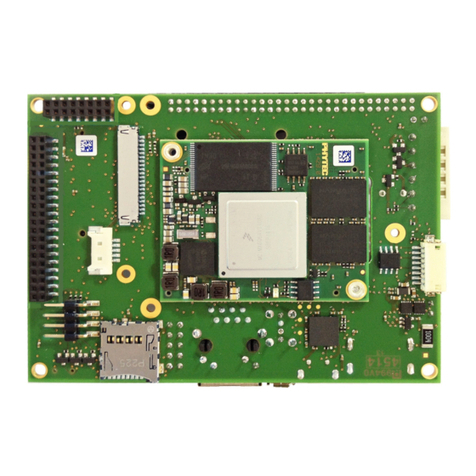
Entec ETMFC610 User manual

ENTEC
ELECTRIC & ELECTRONIC CO., LTD
ENTEC
Copyright © 2018 by ENTEC ELECTRIC & ELECTRONIC CO., LTD all right reserved. Forerunner Distribution & Automation
Release Date: Aug. 2019 / Manual Revision:1.04
MULTI-FUNCTION CONTROL
ETMFC610
USER’S MANUAL


Multi-Function Control ETMFC610 http://www.entecene.co.kr
i
EN
HANCED
TEC
HNOLOGY
Release Note:
[May. 2018] Ver1.00
New user manual for ETMFC610
[Oct. 2018] Ver1.01
Add “Multi-Bit Protocol”
[Feb. 2019] Ver1.02
Add “FI Auto Reset” function.
[May. 2019] Ver1.03
Add “Negative Sequnce Over Voltage” function.
[Aug. 2019] Ver1.04
Modify to the latest H/W Drawings.

Multi-Function Control ETMFC610 http://www.entecene.co.kr
ii
EN
HANCED
TEC
HNOLOGY
TABLE OF CONTENTS
1. INTRODUCTION ........................................................................................................... 1
1.1. Description .......................................................................................................................... 1
1.2. Summary of Features ........................................................................................................... 2
2. TECHNICAL SPECIFICATIONS ................................................................................ 7
2.1. Inputs and Outputs ............................................................................................................... 7
2.2. Type Withstand Tests ........................................................................................................... 9
2.3. Metering Accuracy ............................................................................................................ 11
2.4. Fault Indication Type Functions ........................................................................................ 12
2.5. Protection Type Functions ................................................................................................. 13
2.6. Direction Controls ............................................................................................................. 15
2.7. Cold Load Pickup .............................................................................................................. 16
2.8. Loop Control ..................................................................................................................... 16
2.9. Monitoring ......................................................................................................................... 17
2.10. Recorder .......................................................................................................................... 25
2.11. Communications .............................................................................................................. 31
3. APPLICATION ............................................................................................................. 32
4. DIMENSIONS AND CONSTRUCTION .................................................................... 33
5. SIDE PANEL CONSTRUCTION ................................................................................ 34
5.1. Communication Port .......................................................................................................... 35
5.2. NTC Connector ................................................................................................................. 37
5.3. Current Input Connector .................................................................................................... 38
5.4. Voltage Input Connector .................................................................................................... 38
5.5. Status Inputs Connector ..................................................................................................... 39
5.6. Outputs Connector ............................................................................................................. 39
5.7. SCADA Connector (Option) ............................................................................................. 40
5.8. Power Input / Battery Input Connector ............................................................................. 40
5.9. Power Output Connector ................................................................................................... 41
5.10. Charge Circuit ................................................................................................................. 41
5.11. Battery Protection ............................................................................................................ 42
5.12. Typical Wiring Diagram .................................................................................................. 43

Multi-Function Control ETMFC610 http://www.entecene.co.kr
iii
EN
HANCED
TEC
HNOLOGY
6. USER INTERFACE PANEL ........................................................................................ 44
6.1. Construction ...................................................................................................................... 45
6.1.1. Operation Section ................................................................................................... 45
6.1.2. Local Control Section ............................................................................................. 46
6.1.3. Menu Control Section ............................................................................................ 49
6.1.4. Fault Indication Section ......................................................................................... 51
6.1.5. Voltage Element Section......................................................................................... 51
6.1.6. System Diagnostic Section ..................................................................................... 51
6.1.7. Battery Status Section ............................................................................................ 52
6.1.8. User LED Section ................................................................................................... 52
6.1.9. Set Group Status Section ........................................................................................ 53
6.2. LCD Display ..................................................................................................................... 54
6.2.1. Menu Structure Tree ............................................................................................... 54
6.2.2. GLOBAL Setting ................................................................................................... 57
6.2.3. GROUP Setting ...................................................................................................... 58
6.2.4. Event ...................................................................................................................... 59
6.2.5. Maintenance ........................................................................................................... 59
6.2.6. Time ........................................................................................................................ 59
6.2.7. Status ...................................................................................................................... 59
6.2.8. Metering ................................................................................................................. 59
6.3. Using the LCD Menu ........................................................................................................ 60
6.3.1. Initial Screen .......................................................................................................... 60
6.3.2. Main Menu ............................................................................................................. 63
6.3.3. Setting Example ..................................................................................................... 63
6.3.4. Setting Save ............................................................................................................ 64
7. GLOBAL SETTING ..................................................................................................... 65
7.1. General Setting .................................................................................................................. 65
7.1.1. System .................................................................................................................... 66
7.1.2. Event Recorder ....................................................................................................... 73
7.1.3. Monitoring .............................................................................................................. 76
7.1.4. Loop Control .......................................................................................................... 93
7.1.5. Passcode ................................................................................................................110
7.1.6. PLC ....................................................................................................................... 111
7.1.7. Device .................................................................................................................. 120
7.1.8. Save Setting .......................................................................................................... 129

Multi-Function Control ETMFC610 http://www.entecene.co.kr
iv
EN
HANCED
TEC
HNOLOGY
7.2. Communication ............................................................................................................... 130
7.2.1. Protocol Setup ...................................................................................................... 130
7.2.2. Port Setup ............................................................................................................. 164
7.2.3. RTU Communication (Dialup Modem) Setup...................................................... 171
7.2.4. FTP-SSL ............................................................................................................... 176
7.2.5. Wifi ....................................................................................................................... 177
7.2.6. Event & Etc Setup ................................................................................................ 178
7.2.7. Save Setting .......................................................................................................... 182
8. GROUP SETTING ...................................................................................................... 183
8.1. Fault Indication ................................................................................................................ 184
8.1.1. FI Type.................................................................................................................. 184
8.1.2. FI Pickup Current ................................................................................................. 185
8.1.3. FI Setting Time ..................................................................................................... 186
8.1.4. Inrush Restraint .................................................................................................... 190
8.1.5. FI Auto Reset ........................................................................................................ 191
8.2. Protection......................................................................................................................... 192
8.2.1. Phase Time Overcurrent (51P) ............................................................................. 195
8.2.2. Ground Time Overcurrent (51G) .......................................................................... 200
8.2.3. Negative Sequence Overcurrent (51Q(46)) .......................................................... 204
8.2.4. Phase Instantaneous Overcurrent (50P) ................................................................ 208
8.2.5. Ground Instantaneous Overcurrent (50G) ............................................................ 210
8.2.6. Sensitive Earth Fault (50SG) ................................................................................ 212
8.2.7. Negative Sequence Instantaneous Overcurrent (50Q) .......................................... 214
8.2.8. Inrush Restraint .................................................................................................... 216
8.2.9. User Curve - Time Overcurrent Curves ................................................................ 225
8.3. Directional Controls (67) ................................................................................................. 260
8.3.1. Phase Directional Controls (67P) ......................................................................... 260
8.3.2. Ground Directional Controls (67G) ...................................................................... 263
8.3.3. SEF Directional Controls (67SEF) ....................................................................... 265
8.3.4. Negative Sequence Directional Controls (67Q) ................................................... 266
8.4. Cold Load Pickup ............................................................................................................ 269
8.5. Monitoring ....................................................................................................................... 272
8.5.1. Broken Conductor(46BC) .................................................................................... 272
8.5.2. Voltage (27/59/64N/47P) ...................................................................................... 274
8.5.3. Frequency (81) ..................................................................................................... 278
8.5.4. Power (32) ............................................................................................................ 286

Multi-Function Control ETMFC610 http://www.entecene.co.kr
v
EN
HANCED
TEC
HNOLOGY
8.5.5. Demand (49) ......................................................................................................... 290
8.5.6. Phase Difference................................................................................................... 292
8.5.7. Synchro’ Check (25) ............................................................................................. 294
8.5.8. Open Phase ........................................................................................................... 298
8.5.9. Live Line Block .................................................................................................... 299
8.5.10. Fault Locator ...................................................................................................... 300
8.5.11. Load Current Alarm ............................................................................................ 303
8.5.12. Power Factor (55) ............................................................................................... 305
8.6. Save Setting ..................................................................................................................... 306
9. EVENT RECORDER .................................................................................................. 307
9.1. Operation Event............................................................................................................... 308
9.2. Fault Event ...................................................................................................................... 309
9.3. Fault Cycle - Summary ....................................................................................................311
9.4. System Event ................................................................................................................... 312
9.5. Set Change Event ............................................................................................................ 313
9.6. Load & Energy Event ...................................................................................................... 314
9.6.1. Load & Energy/Min. Event .................................................................................. 314
9.6.2. Load & Energy/Hour Event ................................................................................. 316
9.6.3. Load & Energy/Day ............................................................................................. 317
9.6.4. Load & Energy Field Configuration..................................................................... 318
9.7. Diagnostic Event ............................................................................................................. 319
9.8. PQM Event ...................................................................................................................... 321
9.9. Load Current Alarm Event .............................................................................................. 322
9.10. Clear Saved Data ........................................................................................................... 324
10. MAINTENANCE ...................................................................................................... 325
10.1. Count ............................................................................................................................. 325
10.1.1. ETMFC610 Count ............................................................................................. 325
10.1.2. Fault Count ......................................................................................................... 326
10.1.3. PQM Count ........................................................................................................ 327
10.1.4. Communication Count ....................................................................................... 331
10.1.5. User Count.......................................................................................................... 332
10.2. Interrupt Time ................................................................................................................ 333
10.3. Contact Wear ................................................................................................................. 333
10.4. Data Reset ..................................................................................................................... 334
10.5. Controller Information .................................................................................................. 334

Multi-Function Control ETMFC610 http://www.entecene.co.kr
vi
EN
HANCED
TEC
HNOLOGY
10.6. Mechanism Scale ........................................................................................................... 335
11. TIME........................................................................................................................... 336
12. STATUS ...................................................................................................................... 337
12.1. ETMFC610 .................................................................................................................... 337
12.2. Input Ports ..................................................................................................................... 339
12.3. Output Ports ................................................................................................................... 339
12.4. GOOSE Single Input ..................................................................................................... 340
12.5. GOOSE Double Input ................................................................................................... 340
12.6. GOOSE Output .............................................................................................................. 341
12.7. Latch Logic.................................................................................................................... 341
12.8. Diagnostic ...................................................................................................................... 342
13. METERING ............................................................................................................... 343
13.1. Current ........................................................................................................................... 343
13.2. Voltage ........................................................................................................................... 344
13.3. Frequency ...................................................................................................................... 346
13.4. Power ............................................................................................................................. 347
13.5. Energy ........................................................................................................................... 348
13.6. Demand Current and Power .......................................................................................... 349
13.7. Unbalance ...................................................................................................................... 351
13.8. Harmonics ..................................................................................................................... 352
13.9. True R.M.S .................................................................................................................... 352
13.10. Controller Reference ................................................................................................... 353
14. MAINTANANCE ...................................................................................................... 354
14.1. Warning Events.............................................................................................................. 354
15. PLC function .............................................................................................................. 357
16. Function of File Transfer Protocol ........................................................................... 358
16.1. Patching firmware to upgrade ....................................................................................... 358
16.2. COMTRADE................................................................................................................. 359
16.2.1. File format and Name ......................................................................................... 359
16.2.2. Related Setting Items .......................................................................................... 359
17. Wireless Connection .................................................................................................. 360
17.1. Connection using WIFI (PC) ......................................................................................... 360
17.2. Connection using Smart ETIMS ................................................................................... 361

Multi-Function Control ETMFC610 http://www.entecene.co.kr
vii
EN
HANCED
TEC
HNOLOGY
17.3. Security ......................................................................................................................... 362
17.3.1. SSL / TLS ........................................................................................................... 362
17.3.2. AES .................................................................................................................... 362


Multi-Function Control ETMFC610 http://www.entecene.co.kr
1
EN
HANCED
TEC
HNOLOGY
1. INTRODUCTION
1.1. Description
ETMFC610 is a multi-functional control unit built-in with RTU (Remote Terminal Unit) for
distribution automation system (DAS), supporting the communication protocols such as DNP3.0,
MODBUS™, IEC60870-5-101, IEC60870-5-104 and IEC61850(option).
It provides the fault indication, monitoring and control of distribution system based on accurate
measurements. It can also save and manage the various events and load profiles that are useful for
analyzing the cause of the line fault.
The ETMFC610 supports 6 setting group, PLC (Programmable Logic Control, Scada I/O ports and
user programmable lamps etc. to provide convenient application in various distribution
environment. Especially, PLC (Programmable Logic Control), Scada I/O ports and user
programmable lamps does not require any H/W change for implementing number of Input/Output
signal and status indications.
Moreover, it is operated based on Linux OS that can provide the user with comfortable and useful
operation technology such as smart mobile App. function (optional), WIFI (optional), USB port and
remote access of distribution line equipment.
By the remote access and the file managing system, the user is not required to visit the actual site
for upgrading the program, or downloading and uploading of recorded files in COMTRADE
standard format and setting changes respectively.
Due to convenient remote access, the security is strengthed by AES256/SHA256 coding and user
access authorization and control.

Multi-Function Control ETMFC610 http://www.entecene.co.kr
2
EN
HANCED
TEC
HNOLOGY
1.2. Summary of Features
FAULT INDICATION
Phase Fault Indication
Ground Fault Indication
Sensitive Earth Fault Indication
Negative Sequence Fault Indication
Inrush Restraint and Cold Load Pickup
Phase, Ground, Sensitive Earth Fault and Negative Sequence Directional Controls
Auto Sectionalizer (Loop Control)
Tie Point Switch (Loop Control)
PROTECTION
Dual Phase Time Overcurrent Elements
Dual Phase Instantaneous Overcurrent Elements
Dual Ground Time Overcurrent Elements
Dual Ground Instantaneous Overcurrent Elements
Dual Sensitive Earth Fault Elements
Dual Negative Sequence Time Overcurrent Elements
Dual Negative Sequence Instantaneous Overcurrent Elements
Inrush Restraint and Cold Load Pickup
Phase, Ground, Sensitive Earth Fault and Negative Sequence Directional Controls

Multi-Function Control ETMFC610 http://www.entecene.co.kr
3
EN
HANCED
TEC
HNOLOGY
MONITORING (COMMON)
Broken Conduct Element
Two Under Voltage Elements
Two Over Voltage Elements
Two Neutral Over Voltage Elements
Two Negative Sequence Over Voltage Elements
Two Under Frequency Elements
Two Over Frequency Elements
Frequency Decay Element
Two Forward Power Elements
Two Directional Power Elements
Phase Current, Ground Current, Negative Sequence Current, Active Power and Reactive
Power Demand Elements
Phase Difference
Synchro’ Check
Open Phase
Live Line Block
Fault Locator
Load Current Alarm
Power Factor (Lead and Lag)
Live Line
Operation Count
Contact Wear per Phase
Battery Automatic Load Test & Battery Management
Power Quality
- Interrupt, Sag and Swell
- Harmonics
- Current Unbalance
- Voltage Unbalance
- Under Voltage
- Over Voltage
- Under Frequency
Breaker Failure with Current Supervision
System Power

Multi-Function Control ETMFC610 http://www.entecene.co.kr
4
EN
HANCED
TEC
HNOLOGY
EVENT RECORDER
Switch(or CB) Operation Recorder – last 5,000 events
Fault Event Recorder – last 1,500 events
Fault Waveform(60 cycles× 64 samples) – last 32 events
System Event Recorder – last 5,000 events
Setting Change Event Recorder – last 2,000 events
Load&Energy Recorder
- Average Load & Energy – last 8,640 events (Max 360 days)
- Peak Load & Energy in every hour – last 8,640 events
- Peak Load & Energy in every day – last 8,640 events
Diagnostic Event Recorder - last 2,000 events
PQM Detection Event Recorder - last 1,500 events
Load Current Alarm Event Recorder - last 1,500 events
NOTE : 1. The maximum number of all events except fault waveform to be stored can be
increased according to user requests.
2. According to sting, waveform can support COTRADE format.
MAINTENANCE
Restart, Diagnostic and Operation counters
Fault Trip and Fault counters
PQM counters
Communication counters
User counters
Interrupt Time
Contact Wear per Phase

Multi-Function Control ETMFC610 http://www.entecene.co.kr
5
EN
HANCED
TEC
HNOLOGY
METERING
Each Phase Current and Phasor : Ia, Ib, Ic, Ig, Isef
Each Phase Pick Current : Ia, Ib, Ic, Ig, Iq
Each Phase and Line to Line Voltage and Angle : Va, Vb, Vc, Vr, Vs, Vt, Vab, Vbc, Vca, Vrs,
Vst, Vtr
Current and Voltage Symmetrical Component : I1, I2, 3I0, V1, V2, 3V0
Source and Load side Frequency, Frequency Change Rate, Slip Frequency and Slip Angle
Single Phase and Three Phase Power : Active Power(kW), Reactive Power(kVar), Apparent
Power(kVA), Power Factor(%)
Positive and Negative Energy : Active Energy(kWh), Reactive Energy(kVarh)
Present and Positive/Negative Maximum Demand
- Demand Current : Ia, Ib, Ic, In, Iq
- Single Phase and Three Phase Active Power(kW) and Reactive Power(kVar)
Source/Load side Voltage and Current Unbalance
Voltage and Current Harmonics (THD, 2nd ~ 31th order)
Voltage and Current True R.M.S
ETMFC610 Condition Reference
- Battery Voltage, Charger Voltage and Charger Current
- Battery Capacity
- ETMFC610 Internal Temperature
- ETMFC610 External Temperature
- System Power : +12V, -12V, Reference Voltage
COMMUNICATIONS
Side panel RS232-1 and RS232-2 Serial Port : DNP 3.0, Modbus, IEC60870-5-101 and Multi-
Bit Protocol, ETMFC610 Interface Software
Side panel RS485 Port : DNP 3.0, Modbus, IEC60870-5-101 and Multi-Bit Protocol
Side panel Eth1 and Eth2 Ethernet Port or Fiber Optic(Option) Port : DNP 3.0, Modbus,
IEC61850(option), IEC60870-5-104 and Multi-Bit Protocol, ETMFC610 Interface Software
Front Panel USB-B Type Port : ETMFC610 Interface Software

Multi-Function Control ETMFC610 http://www.entecene.co.kr
6
EN
HANCED
TEC
HNOLOGY
USER INTERFACE
Fault Indicators
Manual Battery Load Test: Battery Voltage and Charge Voltage
Dual Functional Keypads
20×8 Character LCD Display
49 LED indicators - Fault indications, Sequence status, Battery status, etc.
Setting Range Help Messages
Access Security(3 Passwords with Different Authorities)
OTHERS
Programmable Logic Control(PLC)
Time Synchronism Device (IRIG) – Option
Wifi – Option
AUXILIARY INPUTS
12 Opto-isolated Programmable Inputs – Option
AUXILIARY OUTPUTS
8 Opto-isolated Programmable Outputs – Option

Multi-Function Control ETMFC610 http://www.entecene.co.kr
7
EN
HANCED
TEC
HNOLOGY
2. TECHNICAL SPECIFICATIONS
2.1. Inputs and Outputs
SYSTEMS
3phase-3wire or 3phase-4wire, 38㎸ maximum, 800 Amp maximum
FREQUENCY
50 / 60㎐ system and ABC/ACB phase rotation
CONTROL VOLTAGE INPUT
AC Voltage Input 24Vac (±20%)
Nominal Battery Voltage : 24Vdc
Power Consumption : 8.4W at 24V dc
USER AVAILABLE DC POWER OUTPUT
DC Power Voltage : 24Vdc or (12Vdc, 15Vdc option)
DC Power Continuous : 40W(60W/1 min)
VOLTAGE TRANSFORMER INPUTS (VT)
Voltage Inputs Va, Vb, Vc, Vr, Vs, Vt(
Input Voltage Range : Phase-Neutral Continuous <8V
Burden: 0.002VA(4V)
VOLTAGE TRANSFORMER INPUTS (VT) - Option
Voltage Inputs Va, Vb, Vc, Vr, Vs, Vt
Input Voltage Range : Phase-Neutral Continuous <300V
Burden: 0.6VA(300V), 0.2VA(220V), 0.05VA(120V), 0.02VA(67V)

Multi-Function Control ETMFC610 http://www.entecene.co.kr
8
EN
HANCED
TEC
HNOLOGY
CURRENT TRANSFORMER INPUTS (CT)
Current Inputs Ia, Ib, Ic, In and Isef
Ia, Ib, Ic, In Input Current Range
1A Nominal
2A continuous
25A 1 second
Burden : 0.38VA(1A)
Ise Input Current Range
0.05A Nominal
0.16A Continuous
0.6A 1 second
Burden : 0.0375VA(0.05A)
CONTROL INPUTS - Option
Control Inputs 12 Channel
Nominal Voltages and Operating Range
12V..24Vdc (-15%, +20%)
125Vdc (-15%, +20%)
250Vdc (-15%, +20%)
Operating current : < 5mA at Nominal Voltages
CONTROL OUTPUT CONTACTS - Option
Control Outputs 8 Channel
300Vac / 350Vdc Varistor for differential surge protection
Operate / Release time : < 5ms at +20℃(+68℉)
Maximum operating power
Table 2-1. Control Output Contacts
(L/R=7ms)
125Vdc 0.1A
48Vdc 0.8A
24Vdc 3A
(cosΦ=0.4) 250Vac 3A
125Vac 5A

Multi-Function Control ETMFC610 http://www.entecene.co.kr
9
EN
HANCED
TEC
HNOLOGY
2.2. Type Withstand Tests
Electromagnetic Compatibility Immunity
Electrostatic Discharge Immunity : IEC 61000-4-2 : 2008
Level 3 and 6㎸ contact, 8 ㎸ air
Radiated electromagnetic field immunity : IEC 61000-4-3 : 2010
10 V/m at 80㎒~1.0㎓ and 1.4㎓~2.7㎓
Electrical Fast Transient Burst Immunity : IEC 61000-4-4 : 2012
2 kV at 5 kHz (Communication Ports)
Surge Immunity : IEC 61000-4-5 : 2017
4 kV line to line
4 kV line to earth
4 kV Comm. ports
Conducted disturbance immunity : IEC 61000-4-6 : 2013
10 V at 150 kHz ~ 80 MHz
Power frequency magnetic field immunity : IEC 61000-4-8 : 2009
100 A/m (Continuous), 1 000 A/m (3s)
Voltage dips, interruption and variation immunity : IEC 61000-4-11 : 2004
Voltage disp immunity test : 0%, 40%, 70%, 80%
Voltage interruptions immunity test : 0%
Voltage variations immunity test : 70 % / 30 cycles
Test for immunity to conducted, common mode disturbances : IEC 61000-4-16 : 2015
30 V (continuous), 300 V (short duration)
Oscillatory wave immunity : IEC 61000-4-18 : 2006
Immunity test for 1 MHz burst ; Comm: 2.5 kV, Differential : 1.0 kV
Immunity test for 100 kHz burst; Comm: 2.5 kV, Differential : 1.0 kV
Emission test : CISPR 11 , Class A

Multi-Function Control ETMFC610 http://www.entecene.co.kr
10
EN
HANCED
TEC
HNOLOGY
Environmental
Cold : IEC 60068-2-1 :2007
Test Ad : 16 hours at -40℃
Dry Heat : IEC 60068-2-2 :2007
Test Ad : 16 hours at +85℃
Damp heat, steady state : IEC 60068-2-3 : 1969
Severity Level : 40℃, 4day
Relative Humidity : 93%
Damp heat, Cyclic : IEC 60068-2-30 : 2005
Severity Level : 25℃ to 55℃, 2cycles
Relative Humidity : 95%
Vibration : IEC 60255-21-1 : 1988
Shock and bump : IEC 60255-21-2 : 1988
Seismic : IEC 60255-21-3 : 1993
Safety
Dielectric Strength : IEC 60255-27 : 2013
2000 Vac on Control inputs, control outputs, and analog inputs, communication for
1minute
Impulse : IEC 60255-27 : 2013, 0.5 J, 5 kV, 1.2/50 ㎲
Insulation resistance : IEC 60255-27 : 2013, 100 ㏁ at 500 V d.c.
Table of contents
