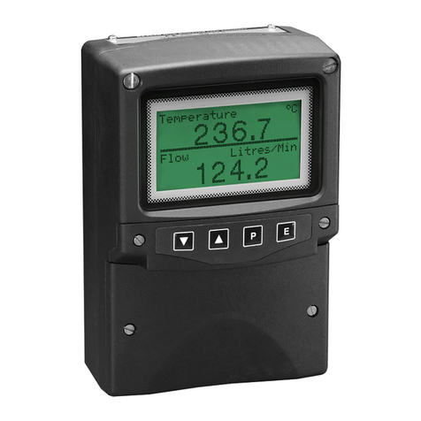
envea LEAK ALERT 73 User manual

LEAK ALERT 73
USER MANUAL


LEAK ALERT 73
Filter Leak Monitor
USER MANUAL
Publication Part No. PC-000834-MA

Publication Part No. 492032
Issue 5
December 2021
Original language: English
Copyright © ENVEA UK Ltd 2021
All rights reserved throughout the world. No part of this
document may be stored in a retrieval system,
transmitted, copied, or reproduced in any way, including,
but not limited to photocopy, photograph, magnetic or
other records without the prior agreement and permission
in writing of ENVEA UK Ltd.
Disclaimer
ENVEA reserves the right to revise and update this
documentation from time to time without obligation to
provide notification of such revision or change. Revised
documentation may be obtainable from ENVEA.
ENVEA reserves the right, without notice, to make changes
in equipment design or performance as progress in
engineering, manufacturing, or technology may warrant.
Trademarks
All product trademarks and registered trademarks are the
property of ENVEA UK Ltd.
All other product trademarks and registered trademarks
are the property of their respective companies.
envea™is a trademark of the ENVEA Group.
Feedback
ENVEA encourages customer feedback and welcomes
any comments or suggestions relating to the product or its
documentation.
Published by:
Technical Publications
ENVEA UK Ltd
ENVEA House
Rose & Crown Road
Swavesey,
CB24 4RB, United Kingdom
Email: technicalpublications.GB@envea.global

LEAK ALERT 73
ENVEA UK Ltd (PC-000834-MA Issue 5, December 2021)December 2021 v
Table of Contents
Table of Contents ............................................................................................... v
List of Figures ...................................................................................................vii
1INTRODUCTION ____________________________________________ 1
1.1 Purpose of this Manual ............................................................................... 1
1.2 Product Safety .......................................................................................... 1
1.2.1 Danger from Process ......................................................................... 1
1.3 Safety Procedures ................................................................................. 2
1.4 Intended Use ............................................................................................ 3
1.4.1 Limits of Use .................................................................................... 3
1.5 Additional Information................................................................................ 3
1.5.1 Related Documentation ..................................................................... 3
1.5.2 Product Parts and Options.................................................................. 3
1.6 Certification .............................................................................................. 4
1.7 Conformance and Related Standards............................................................ 4
2PRODUCT DESCRIPTION _____________________________________ 5
2.1 Overview.................................................................................................. 5
2.2 Technical Specification ............................................................................... 5
2.2.1 Sensor Options................................................................................. 6
2.2.2 Cabling............................................................................................ 6
2.2.3 PC Software Suite (PC-ME DUST TOOLS) ............................................. 6
3SENSOR INSTALLATION _____________________________________ 7
3.1 Introduction.............................................................................................. 7
3.2 Unpacking and Storage .............................................................................. 7
3.3 Prerequisites and Guidelines ....................................................................... 7
3.3.1 Location Requirements ...................................................................... 7
3.3.2 Power Supply to the Sensor ............................................................... 7
3.3.3 Cable Routing Guidelines ................................................................... 8
3.3.4 Grounding the Sensor ....................................................................... 8
3.4 Installing and Connecting the Sensor ........................................................... 8
3.4.1 Safety Information............................................................................ 8
3.4.2 Fitting the Sensor to the Stack ........................................................... 9
3.4.3 Sensor Connections ........................................................................ 10
3.5 Connecting the Power Supply.................................................................... 11
3.5.1 Connecting the Cables..................................................................... 11
3.5.2 Wiring the Mains Power Supply......................................................... 11
3.5.3 Wiring the 24V DC Supply................................................................ 12
4USER CONTROLS AND MENU SELECTION________________________ 13
4.1 Overview of Internal Controls.................................................................... 13
4.2 Navigation and Basic Functionality ............................................................. 14
4.2.1 Accessing Menus and Menu Options .................................................. 14
4.2.2 Changing a Setting ......................................................................... 14
5INSTRUMENT SETTINGS: STANDARD MENU _____________________ 15
5.1 Standard Menus –Scaling Methods............................................................ 15
5.1.1 Scaling Method 1 –% of 4-20mA...................................................... 15
5.1.2 Scaling Method 2 –Scaling Factor (Option) ........................................ 16
5.2 Entering or Changing the Password [PASS]................................................. 17
5.3 Sensitivity [SENS] ................................................................................... 17
5.4 Display Smoothing [DISP] ........................................................................ 17

LEAK ALERT 73
vi (PC-000834-MA Issue 5, December 2021) ENVEA UK Ltd
5.4.1 Changing the Display Smoothing Filter .............................................. 17
5.5 Scaling Methods ...................................................................................... 18
5.5.1 Scaling Method 1 –Scaling to % of 4-20 mA Output [SCAL] ................. 18
5.5.2 Scaling Method 2 –Setting a Scaling Factor [SF] ................................ 18
5.6 4-20mA Span [4-20mA] (Scaling Method 2 only)......................................... 19
5.6.1 Adjusting the 4-20mA Settings ......................................................... 19
6INSTRUMENT SETTINGS: ENGINEERING MENU [ENG] _____________ 20
6.1 Advanced Functions ................................................................................. 21
6.1.1 Switching to the Engineering Setup................................................... 21
6.2 4-20mA Filter [4_20 FLTR] ....................................................................... 21
6.2.1 Changing the 4-20mA Filter ............................................................. 21
6.3 Emission Alarm Settings [ALA1, ALA2] ....................................................... 22
6.3.1 Set Points [SP1, SP2] ...................................................................... 22
6.3.2 Averaging Filter .............................................................................. 22
6.3.3 Alarm Delay [DEL1, DEL2] ............................................................... 22
6.3.4 Change the Alarm Settings –Relay 1 [ALA1]...................................... 23
6.3.5 Change the Alarm Settings –Relay 2 [ALA2]...................................... 23
6.4 Plant Stop Function [PL.ST] ...................................................................... 23
6.4.1 Enable the Plant Stop Option............................................................ 24
6.4.2 Summary of Plant Stop Behaviour..................................................... 24
6.5 Comms Settings ...................................................................................... 24
6.5.1 RS-485 Settings [R485] .................................................................. 24
6.5.2 Changing the RS-485 Settings.......................................................... 24
6.5.3 RS-232 Settings [RS232]................................................................. 25
6.6 Engineering Settings [ENG] ...................................................................... 25
6.6.1 Trimming the 4-20mA Outputs [420Z, 420F] ..................................... 25
6.6.2 Test Functions [T.REL, T.DIG, T.LED] ................................................ 26
6.7 Modbus Diagnostics [MOD.R, MOD.E]......................................................... 26
6.7.1 Reading Modbus Register Values [MOD.R] ......................................... 26
6.7.2 Editing Modbus Register Values [MOD.E] ........................................... 26
7QUALITY ASSURANCE AND SELF-TESTS ________________________ 27
7.1 Sensor Tests (Options)............................................................................. 27
7.1.1 Sensor Checks –Pass Levels ............................................................ 27
7.1.2 Frequency of Sensor Checks............................................................. 27
7.1.3 Running Self-tests [RUN.T] .............................................................. 28
7.1.4 Viewing Self-Test Results................................................................. 28
7.1.5 Self-Test LED ................................................................................. 28
8MAINTENANCE____________________________________________ 29
8.1 Safety Information .................................................................................. 29
8.2 Inspecting and Cleaning the Sensor ........................................................... 29
8.3 Changing the Fuse (Mains-powered Sensors only) ....................................... 31
APPENDIX A _________________________________________________ 32
A.1 Resetting the Sensor [RSET]..................................................................... 32
GENERAL COMPLIANCE _________________________________________ 33
Waste of Electrical and Electronic Equipment (WEEE) Directive (2012/19/EU) . 33
RoHS Compliance Statement .................................................................... 33
List of Materials....................................................................................... 33
INDEX ______________________________________________________ 34
ENVEA SERVICE AND SUPPORT CENTRES ___________________________ 36

LEAK ALERT 73
ENVEA UK Ltd (PC-000834-MA Issue 5, December 2021)December 2021 vii
List of Figures
Fig. 1: Fitting the sensor to the stack.................................................................... 9
Fig. 2: Sensor PCB connections. ......................................................................... 10
Fig. 3: Sensor wiring label –AC versions (inside enclosure lid)............................... 11
Fig. 4: Power supply label (mains)...................................................................... 12
Fig. 5: Sensor wiring label –24V versions (inside enclosure lid). ............................ 12
Fig. 6: Internal sensor controls. ......................................................................... 13
Fig. 7: Standard menu –Scaling method 1 (% of 4-20mA)................................... 15
Fig. 8: Standard menu –Scaling method 2 (SF)................................................... 16
Fig. 9: Engineering menu [ENG] (based on scaling method 1)................................ 20

LEAK ALERT 73
viii (PC-000834-MA Issue 5, December 2021) ENVEA UK Ltd
[This page is left blank intentionally.]

LEAK ALERT 73 1 Introduction
ENVEA UK Ltd (PC-000834-MA Issue 5, December 2021) 1
1Introduction
1.1 Purpose of this Manual
This manual contains all information necessary for the correct installation, setup,
operation, and instrument maintenance. The procedures given in this manual
must be carried out only by suitably trained and qualified personnel.
1.2 Product Safety
The following symbols are used throughout this manual to indicate procedures
that, if not followed correctly, may result in personal injury or damage to
equipment.
WARNING
Alerts the user to a procedure or practice that can result in personal injury
or injury of others if not followed correctly.
CAUTION
Alerts the user to a procedure or practice that can result in damage to the
system or ancillary equipment if not followed correctly.
NOTE
Notes are used to highlight important information that may assist the
reader in carrying out a procedure or understand the text.
In addition, the following symbols are used on the product:
WARNING
Electric shock.
Protective Earth
1.2.1 Danger from Process
The sensor may be installed in ducting that contains process particulate (and other
flue gas constituents) hazardous to health. This may take one or more of the
following forms:
Particulate which is inflammable or explosive
Particulate which is toxic or in some other way hazardous to health
Particulate contained within high-temperature gas.
Take Precautionary Measures
Unless the process conditions are known to be entirely safe, suitable precautions
such as the use of breathing apparatus or duct purging/detoxifying must be
employed before any entry is made into the duct for installation or maintenance
purposes. If in doubt, consult your local Safety Officer and/or local safety
procedures.

1 Introduction LEAK ALERT 73
2(PC-000834-MA Issue 5, December 2021) ENVEA UK Ltd
1.3 Safety Procedures
Always observe the following safety precautions. Personnel installing, operating,
or maintaining the equipment are responsible for their personal safety and for the
correct handling and use of the equipment in accordance with the safety
procedures detailed in this manual.
Follow all warnings and instructions marked on the product and in this manual.
Warning labels are situated on the system, indicating a hazard at or near the
location of the warning label. These safety instructions must be followed to avoid
possible personal injury, injury to others, and damage to the product.
If the equipment is used in a manner not specified in this manual, the protection
provided by the equipment may be impaired.
Retain these instructions in a safe and known place for future use.
WARNING
Risk of personal injury or injury to others. All personnel must be fully
trained and adhere to local and, where applicable, site-specific health and
safety laws and guidelines.
It is the responsibility of the local organisations to enforce safe working
practices at all times.
WARNING
Electric shock.
Only connect to an earthed supply. This unit is a Class 1 construction and
must be connected to a protective earth connection (GND).
WARNING
This product must be connected to a power supply of the same voltage (V)
and frequency (Hz) as indicated on the product rating plate and provided
in the Technical Specification section of this manual.
A supply cable with an adequate rating must be used. Temperature de-
rating must be considered.
WARNING
Electric shock.
For mains powered units –ensure that mains isolation devices are easily
accessible (within a 2m/6½ ft. radius) to allow the sensor and purge blower
to be switched OFF when at the units.
WARNING
Hazardous voltages.
For mains powered units –switch off and isolate the unit power supply
before opening the sensor front cover.
CAUTION
Position the unit to avoid excessive heat, vibration, humidity, and dust.

LEAK ALERT 73 1 Introduction
ENVEA UK Ltd (PC-000834-MA Issue 5, December 2021) 3
CAUTION
Failure to service or maintain the product, fitting non-approved parts, or
carrying out non-approved alterations or servicing can be dangerous. It
could affect the safety of the product. It may also invalidate the terms and
conditions of the product warranty.
1.4 Intended Use
The LEAK ALERT 73 is a reliable, robust ElectroDynamic® sensor that is particularly
suited for use with fabric-filter type dust collectors (baghouses) dust arrestment
plant where performance approval is not required. The sensor can be configured
for all types of industrial bag filters irrespective of cleaning sequence and offers
optional quality assurance, including electronic drift and contamination checks.
The ENVEA’s LEAK ALERT family of sensors has been designed to detect low and
medium levels of dust leakage in addition to gross filter failure.
1.4.1 Limits of Use
To achieve optimum performance and safe operation, the equipment must be
operated within the limits detailed in the Technical Specification section of this
manual. Operation outside these limits may result in damage to the equipment or
failure to achieve the performance specification.
1.5 Additional Information
1.5.1 Related Documentation
The following product literature may be consulted in conjunction with this manual
as applicable. A Reference Library with supporting information for your product or
system is included with the product documentation.
Included in the reference library:
TN004 Installation Notes (Publication Part Number (PPN): 491021)
TN049 Air Purge Information (PPN: 491019)
TN053 Air Purge Guide for ElectroDynamic®Sensors (PPN: 491023)
For products intended for hazardous area applications, refer to the following
literature:
LEAK ALERT Series and DUST MONITOR 210 (for hazardous area
applications)- User Manual Supplement (PPN: PC-000870-MA).
1.5.2 Product Parts and Options
For details of product options, software, accessories, spares, and upgrade options
for your instrument, please refer to the LEAK ALERT 73 datasheet and order
information available on request and for download from the ENVEA website (see
the reverse of this manual).

1 Introduction LEAK ALERT 73
4(PC-000834-MA Issue 5, December 2021) ENVEA UK Ltd
1.6 Certification
1.7 Conformance and Related Standards
ENVEA UK Ltd hereby declares that this instrument – within the limits specified in
this manual – conforms to the essential requirements and other provisions of the
pursuant of the following:
1. European Union Directives: Low Voltage and EMC.
2. UK Regulation 2016: Low Voltage and EMC.
For details, refer to the relevant Declaration of Conformity (DoC) for this
instrument or system supplied with your order.

LEAK ALERT 73 2 Product Description
ENVEA UK Ltd (PC-000834-MA Issue 5, December 2021) 5
2Product Description
2.1 Overview
The instrument is designed for use as a standalone sensor. It has various outputs
for connection to plant CEM systems. There is no logging capability in the
instrument.
2.2 Technical Specification
Stack temperature range
-20 to 400 °C (-4 to 752 °F)
Ambient temperatureA
-20 to +50 °C (-4 to 122 °F)
Minimum detection level
<0.1 mg/m³
Measurement range
up to 500 mg/m³
Sensor Key Data
Sensor variants
Standard sensor:
▪0–250 °C (up to 482 °F)
▪0–100 °C (up to 212 °F; non-Ex only)
Options:
▪High-temperature: 0 –400 °C (up to 752 °F)
▪Insulated sensor: 0–250 °C (up to 482 °F; non-Ex
only)
Enclosure rating
IP65
Outputs
▪4-20mA (isolated, 500 Ω)
▪Warning alarm relay (SPST 1A@24V DC), fail safe
▪Emission alarm relay (SPST 1A@24V DC), fail safe
▪Option: RS-232 (Modbus) or RS-485 (Modbus)B
Inputs
Plant stop signal (output to zero when the plant is off)
User setup
4-digit display and setup keys (internal; see section 2.2.1
below for additional options).
External indicators
3 off; indicators for power, fault, and emission alarms
Scaling methods
▪Percentage % of 4-20 mA output
▪Option: Scaling Factor
Power requirements
▪100–240V AC 50/60Hz, 32mA
Option: 24V DC, 300mA (from a local source)
Cable entries
3x M20 gland/conduit entries
Stack connection
1.5”BSP
Air purge requirements
It may be required on some applications.
External supply of 5–10 Litres/min of dry, clean (oil-free)
instrument air, depending on dust loading.
A
At monitoring point. Please note that imperial temperatures given are nominal values.
B
The output options are exclusive; the RS-485 connection is required for use with the optional BPU.

2 Product Description LEAK ALERT 73
6(PC-000834-MA Issue 5, December 2021) ENVEA UK Ltd
2.2.1 Sensor Options
Quality Assurance
▪Electronic Zero and Reference drift checks, on-demand
▪Automatic Short-circuit check
Air purge options
▪Standard air purge fitting (1/4”BSP)
▪Air Filter and Regulator assembly
▪Flanged Air Purge Adaptor (standard sensor only)
Rod lengths
Standard probes: 100–500 mm (4–20”, nom.)
Options:
▪Standard sensor: 600, 800, 1000 mm (24, 32, 40”, nom.)
▪Insulated sensor: 200–1000 mm (8–40”, nom.)
Additional options
▪RS-232 external connector (fly lead; non-Ex versions only)
▪External keypad
▪Externally viewable display
▪Bag Pulse Display (graphical display of dust levels)
Hazardous zones
classification
Refer to the appropriate Ex addendum. See Related Documentation on
page 3for more information.
2.2.2 Cabling
For mains connections – cabling should be rated for use up to +65 °C (149 °F) at
least to allow for an ambient temperature of up to +50 °C (122 °F). Consult
Technical Note TN007 Network Cable Lengths for information on sensor cabling
requirements and considerations (see Related Documentation on page 3).
Cables supplied by ENVEA meet these requirements.
Maximum cable lengths
▪RS-232: 15 m (49.2 ft.)
▪RS-485: 1,000 m (0.6 mi / 3,280 ft., nom.)
2.2.3 PC Software Suite (PC-ME DUST TOOLS)
The minimum system specification and requirements (for desktop/laptop PCs) are
shown in the following table.
Operating system
Windows XP or higher
System memory
32 Mb RAM
20 Mb free hard disk space
Monitor
1024 x 768 pixels, high-colour graphics
Data communications
Serial port (for connection to one or more instruments)
Optical disc drive
(DVD/CD)
PC-ME DUST TOOLS software is supplied on a software
CD and is also available for download from the ENVEA
UK website: www.envea.global/s/process-
en/dahs-software/pc-me-dust-tools/.
For information on hardware requirements, contact ENVEA or your local ENVEA
representative. The availability of software modules depends upon the type of
sensor. For more information, see Product Parts and Options on page 3.

LEAK ALERT 73 3 Sensor Installation
ENVEA UK Ltd (PC-000834-MA Issue 5, December 2021) 7
3Sensor Installation
3.1 Introduction
This chapter provides information on unpacking, installing, and setting up the
instrument. It also includes information on requirements and safety guidelines.
3.2 Unpacking and Storage
Remove all transit packaging. Inspect the sensor for signs of damage. If the equip-
ment is to be stored prior to installation, repack in the original transit packaging
and store in a dry environment.
No responsibility for damage arising from the use of non-approved packaging
will be accepted.
NOTE
Ensure all items and accessories specified are present. If not,
contact ENVEA or your local ENVEA representative (see the reverse
of this manual).
3.3 Prerequisites and Guidelines
3.3.1 Location Requirements
When selecting a mounting location for optical sensors, the following should be
considered for optimum performance.
Mount in the longest, straightest, unrestricted duct available
Ensure correct sensor grounding.
Excess vibration will affect sensor readings.
Ambient or radiating temperatures in the vicinity of the mounting location
must not exceed +50 °C (122 °F).
3.3.2 Power Supply to the Sensor
The instrument is available in two versions:
a mains voltage version (100–240V AC)
a 24V DC version.
A label on the internal PSU cover indicates the model, voltage, and fuse type (see
Fig. 4 on page 12 for an example). Connect only to a power supply with a voltage
corresponding to that on the rating plate (on the sensor enclosure).
Ensure the power required for the sensor is made available near the monitoring
point during the preparation stage. For mains-powered sensors, a suitable rated
and clearly marked mains isolation device (with separate fuse) must be installed
in the power supply wiring.
Mains Wiring Safety Rules
1. Trim back insulation no more than 8 mm (0.3”) and ensure that strands are
not left free. Alternatively, use a suitable ferrule.

3 Sensor Installation LEAK ALERT 73
8(PC-000834-MA Issue 5, December 2021) ENVEA UK Ltd
2. The earth wire (GND) should be longer than both the Live (L) and Neutral
(N) to ensure that this will be the last to pull out if the mains cable suffers a
tug.
It is recommended to extend the cable insulation fully through the cable gland so
individual wires are not damaged.
3.3.3 Cable Routing Guidelines
1. Ensure that the cable sheath fully penetrates the sensor cable gland.
2. Fit blanking plugs to unused cable glands.
3. Ensure cable entry glands are tightened to the cable.
4. Support cables at appropriate intervals.
5. Do NOT route cables where they may be at risk from lightning strikes (for
example, overexposed roofs).
3.3.4 Grounding the Sensor
For ElectroDynamic® sensors, the sensor body must be grounded to the stack
wall. Ensure that the instrument is electrically grounded: via the ductwork by the
mechanical connection made between the mechanics and the socket, and by
grounding strap provided.
The sensor must be reliably connected to the stack wall using the grounding
strap (earth wire) provided. The grounding strap must be connected prior to
installing the sensor in the stack and may be disconnected only after
removing the probe from the stack.
The grounding strap, which connects the sensor/instrument enclosure to the
stack, must be long enough so that the instrument may be connected and
removed from the stack without disconnecting.
3.4 Installing and Connecting the Sensor
3.4.1 Safety Information
WARNING
Electric shock.
(1) Ensure that only suitable and rated cable types are used for power
supply and interconnection of equipment.
(2) Mains-powered versions only –when wiring the mains cable, ensure
that the Protective Earth wire (GND) is the longest one so that if the
cable is pulled out accidentally, the Earth wire disconnects last.
WARNING
Electric shock.
For mains-powered versions –A suitable approved and rated two-pole
mains isolation device must be clearly marked and installed close to the
unit (within a 2 m/6½ ft. radius) and readily accessible.

LEAK ALERT 73 3 Sensor Installation
ENVEA UK Ltd (PC-000834-MA Issue 5, December 2021) 9
WARNING
Tripping hazard.
Ensure all cables are routed safely to avoid tripping or entangling hazards
and to avoid kinks and pinches.
3.4.2 Fitting the Sensor to the Stack
1 .............................................................................. Stack wall
2 ........... Stack wall opening/port hole for probe (at least 45 mm)
3 ........................................................................ Weld all round
4 ...................................................................... 1.5”BSP socket
5 ............................................................................... Probe rod
6 ................................................................................ Insulator
7 ...................................................................... 1.5”BSP thread
8 ............................................................................ Floating nut
9 .................................................................................Lock nut
10 ...................................................................Sensor enclosure
Fig. 1: Fitting the sensor to the stack.
1. Drill a hole of at least Ø45 mm ID in the stack where the sensor is to be
located.
2. Fit a 1.5” BSP socket, which must be securely welded to the stack. Ensure
the BSP socket is installed either 90° to the stack or about 5° upward, so
the sensor probe points slightly downward, allowing condensate to drain off
into the stack.
56 7 8910

3 Sensor Installation LEAK ALERT 73
10 (PC-000834-MA Issue 5, December 2021) ENVEA UK Ltd
3. Insert the sensor probe into the socket and secure it with the floating nut.
Ensure the sensor enclosure is upright with the cable entry glands at the
bottom and is adequately supported when tightening the floating nut.
4. Tighten the lock nut. When tightening the lock nut, ensure the floating nut is
held securely with a wrench.
3.4.3 Sensor Connections
1........................................................................... Power IN
C
2................................................................. Mains fuse holder
3.......................... Bus termination switch (set to T/ terminated)
4 ................................................................... 4-20mA output
5......................................................... RS-485 output (option)
6....................... RS-232 output (option, also configuration port)
7............................................................................not in use
8..................................... Relays (2 off) and digital input (1 off)
9......................................... Lid earthing strap (do not remove)
10.............................Connection to CPU board (do not remove)
11........................... Power supply (PSU) cover (do not remove)
Fig. 2: Sensor PCB connections.
C
See wiring diagrams below for the connector terminals (these can be found in the enclosure lid).

LEAK ALERT 73 3 Sensor Installation
ENVEA UK Ltd (PC-000834-MA Issue 5, December 2021) 11
3.5 Connecting the Power Supply
3.5.1 Connecting the Cables
Easily accessible disconnect devices, such as switches or circuit breakers along
with a separate fuse, must be fitted to the power supply wiring for mains-powered
sensors and the purge blower unit. These must be located so they can be reached
easily (within 2m/6½ ft. of the unit).
The isolation devices should connect/disconnect both mains Live (L) and mains
Neutral (N) and must be clearly marked as the disconnecting device for the
instrument.
3.5.2 Wiring the Mains Power Supply
Fig. 3: Sensor wiring label –AC versions (inside enclosure lid).
1. Undo the 4 off screws and open the hinged sensor enclosure lid.
2. Note the label on the power supply cover (see Fig. 4 below).
3. Referring to Fig. 2 above, undo the 2 off screws and remove the power
supply cover.
Mains pin connections (L–R):
L
Live
PE
Protective Earth (GND)
N
Neutral
4. Route the power supply cable through the right-hand cable gland and
connect to the mains power terminals as outlined in the following table.
5. Replace and secure the power supply cover.
6. Close the enclosure lid and secure it with the 4 off screws. Do not over-
tighten.
7. Switch ON power to the sensor.

3 Sensor Installation LEAK ALERT 73
12 (PC-000834-MA Issue 5, December 2021) ENVEA UK Ltd
Fig. 4: Power supply label (mains).
3.5.3 Wiring the 24V DC Supply
Fig. 5: Sensor wiring label –24V versions (inside enclosure lid).
1. Undo the 4 off screws and open the hinged sensor enclosure lid.
2. Undo the 2 off screws and remove the power supply cover.
3. Route the data cable through the right-hand cable gland and connect to the
power supply terminals (POWER IN) as marked on the PCB.
Pin connections (L–R):
Wire colour
POWER IN
connector
+24v
24V DC
NC
not connected
0v
0V
4. Replace and secure the power supply cover.
5. Close the enclosure lid and secure it with the 4 off screws. Do not over-
tighten.
6. Switch ON power to the sensor.
Table of contents
Other envea Monitor manuals

