EOGB X500-2 User manual

E90
-
803
-
001
-
00
5
-
0
1
–
Rev
4
-
1
-
INSTRUCTIONMANUALFOROILBURNERMODELS
X500-2–Lowvoltage–12vdc–Brushedmotor

E90
-
803
-
001
-
00
5
-
0
1
–
Rev
4
-
2
-
Contents
Technicalspecifications
Technicaldata...................................................................................................3
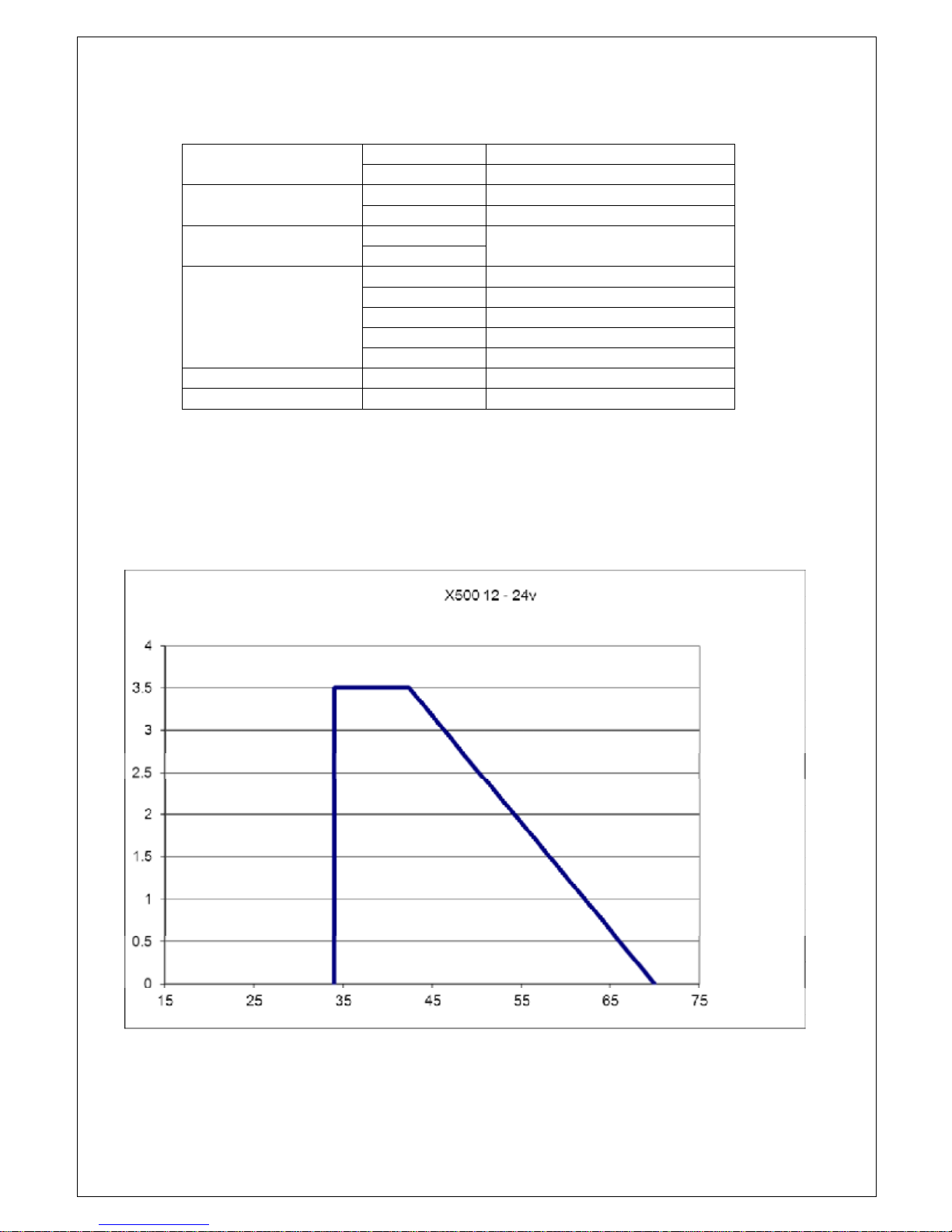
Workingfield.....................................................................................................3
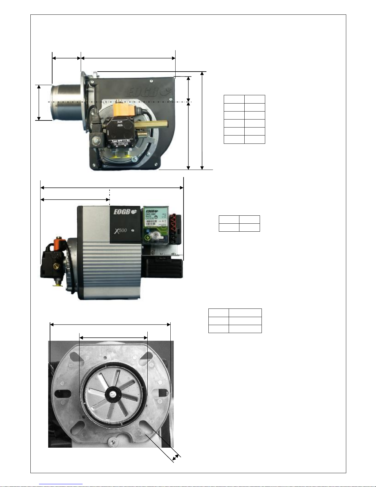
Dimensions........................................................................................................4
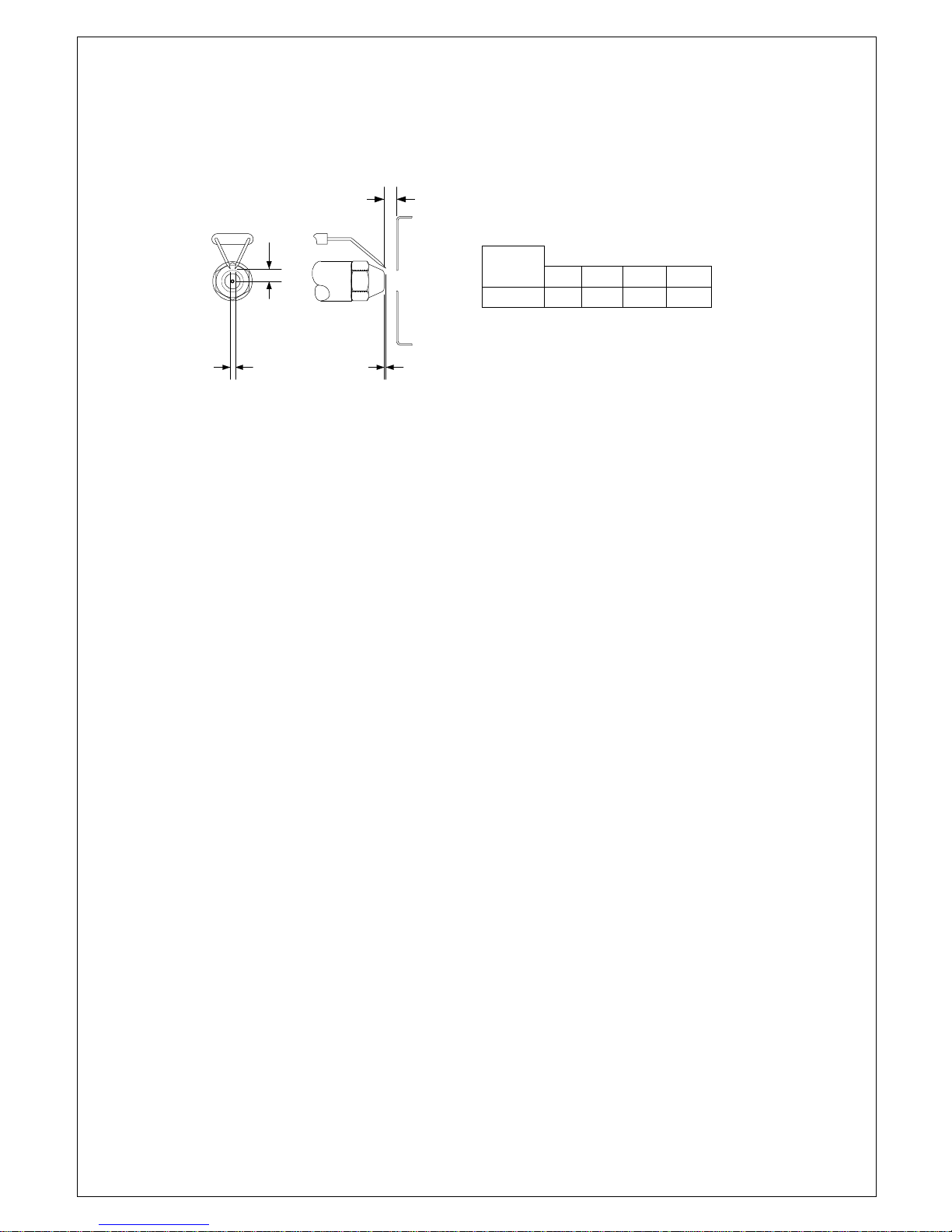
Headandelectrodesettings.............................................................................5
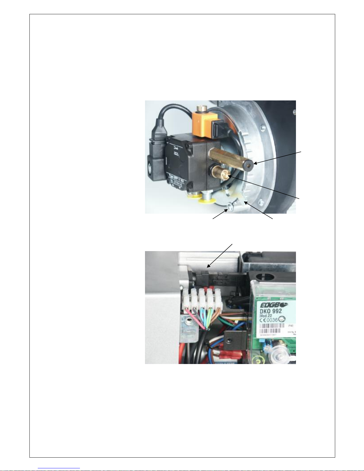
Components......................................................................................................6
Burner installation
Mountingontotheappliance............................................................................7
Electricalconnection.........................................................................................7
Fuelsupply........................................................................................................7
Airsupply...........................................................................................................7
Burneroperation
Beforestart-up..................................................................................................8
Start-upprocedure............................................................................................8
Normaloperating mode....................................................................................9
Burnerservicing
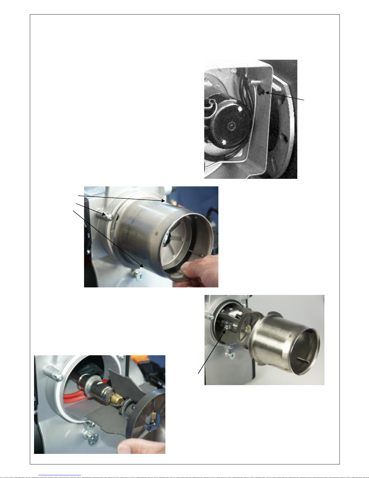
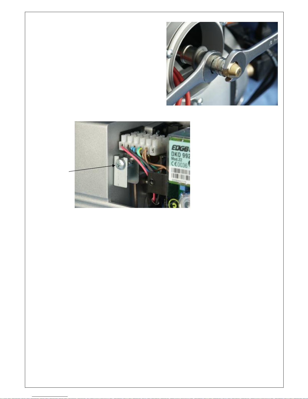
Combustionhead..............................................................................................10
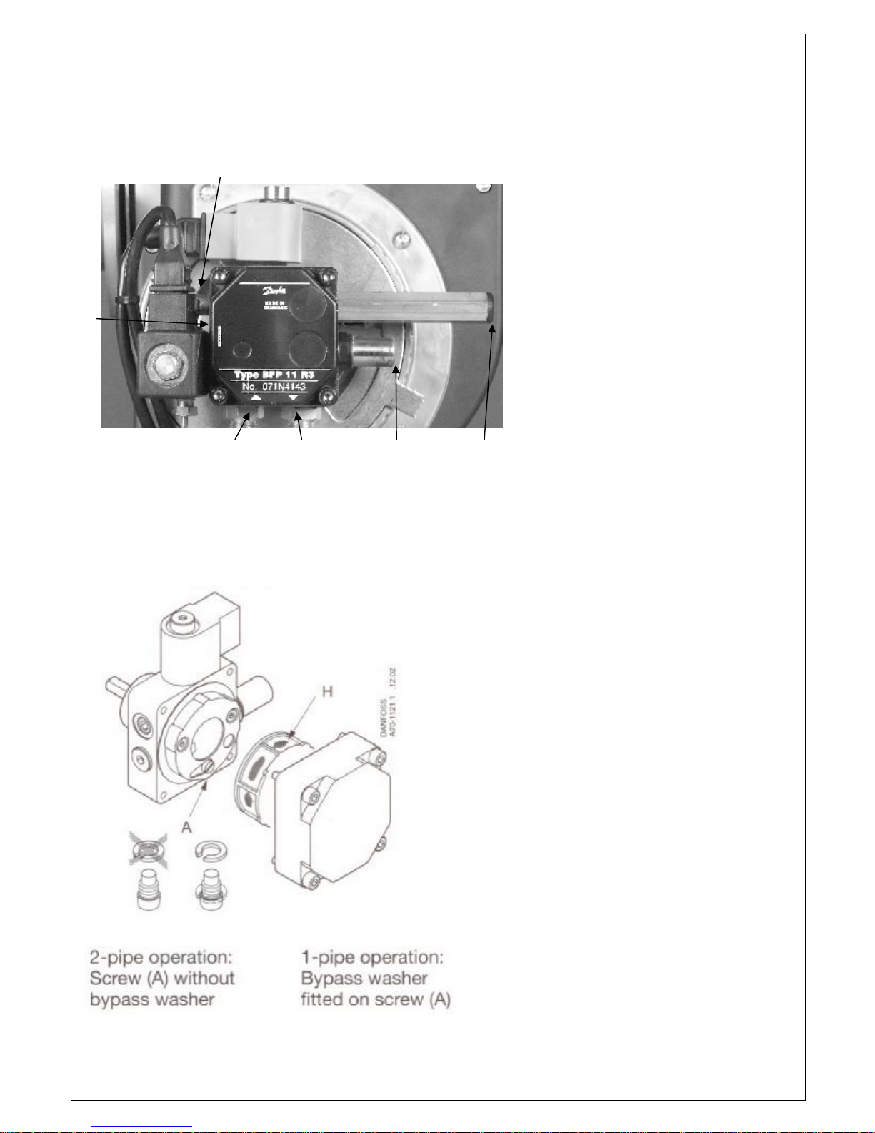
Oilpump............................................................................................................12
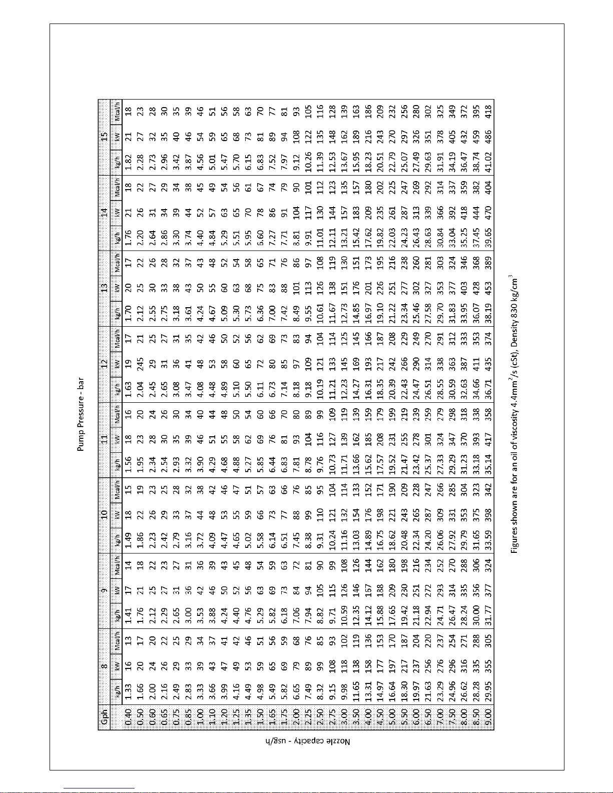
Oilsupplylinetables.........................................................................................14
Nozzle table.......................................................................................................15
Faultfinding table.............................................................................................16
Commissioningreportsheet.............................................................................18
Burnerservicerecord........................................................................................19
Notes.................................................................................................................20
Importantnote
Thecontentsofthemanualmustbereadandfollowedpriortothefittingandcommissioningoftheburner.
Anywork onthisburnermustbecarriedoutbyasuitablyqualified, andexperienced,engineer.
Anyelectricalorfuel supplymustbeisolatedbeforeanywork iscarriedout.
TheinstallationmustbecarriedoutinaccordancewithcurrentElectricalRegulationsand allrelevantBuilding
Regulations.

E90
-
803
-
001
-
00
5
-
0
1
–
Rev
4
-
3
-
Workingfield
Burneroutput
MinkW
30
Max kW
70
Fuel flow rate
MinKg/hr
2.
88
Max Kg/hr
5.
9
Fuel
Kerosene
Maxviscosity5.5 cst@20
o
C
Gasoil
Electricalsupply
Input
12volt dc
Motor
12volt dc brushed
Ignitionunit
24volt dc
Startcu
rrent
21amps
Run current
11.5amps
Weight
10kg
Mode
On
-
off
Technicalspecifications
TechnicalData
Burneroutput
Kw/hr

E90
-
803
-
001
-
00
5
-
0
1
–
Rev
4
-
4
-
A
89
B
80
C
2
3
1
D
50
E
161
F
2
12
G
1
83
H
3
4
0
J
89
K
125
-
150
L
10
Technicalspecifications
Dimensions (mm)
J
K
L
G
H
A
B
F
D
E
C

E90
-
803
-
001
-
00
5
-
0
1
–
Rev
4
-
5
-
BA
C
E
Model
A
B
C
E
X500
-
2
3.5
2.0
6
4.5
Technicalspecifications
Headandelectrodesettings

E90
-
803
-
001
-
00
5
-
0
1
–
Rev
4
-
6
-
1
Blasttube
2
Mounting flange
3
Airintake
4
Fanhouse
5
Airadjuster
6
Lockoutresetbutton
7
Controlbox
8
Photocell
(hidden)
9
Ignit
ionunit
11
Motor
19
24v
–
12vconverter
14
H.T.leads(hidden)
15
Ignitionelectrodes
16
Electrodeholder
17
Nozzle
18
Nozzle assembly
19
Brakeplate
Technical specifications
Components
4
5
1
2
3
6
7
8
9
11
19
14
15
16
17
18
19

E90
-
803
-
001
-
00
5
-
0
1
–
Rev
4
-
7
-
Burnerinstallation
Mountingonto theappliance
Theburnerismountedontotheappliancebymeansofaremovable6-bolt
flange.
Thegasketneedstobeputinplacebeforetheflangeisfixedontothe
appliance.Theburnertubeistheninsertedthroughthecentreholeafter
fitting theO-ringoverthetheblasttube.
Withtheburnerrotatedafew degreesclockwisetheflangebolts willpass
throughthelocatingholes. Whentheburneristwistedintopositionthetop
bolt can thenbetightenedto securetheburner.Ifnecessarythelowerscrew
can beadjustedtogiveamoresecurefixing.
Ifrequiredtheburnercan bemountedinanyposition.Itisimportantthough
to ensurethatthesolenoidvalveontheoil pumpis notinclinedbelow
horizontal.
Electricalconnection
Theelectricalconnectionstothisburnermustbecarriedoutbyasuitablyqualifiedengineer.
AllElectricalconnections totheburner mustbe carried outinaccordancewithall currentapplicableIEE Wiring
Regulations.
Allconnectionsshouldbemadeaccordingto thewiring diagramshownonthesupplementarypage.
Theburnerisfittedwitha7-pinsocket pre-wiredintotheburner.
Fuelsupply
Theburnerisusuallysuppliedfortwo-pipeoperationbutifrequiredcanbeconvertedforaone-pipegravity
system (detailselsewhereinthismanual).Whenusedinconjunctionwithagravityfeedsupplytheinlet pressure
to thepumpMUSTNOTexceed2bar.
Whenusing atwo-pipesystem thereturn linehastobefedbackintothetank.Alternatively, ade-aerationdevice
couldbeincorporatedforeaseofinstallation.
Oillinesmustbecompletelyair-tightandconstructedinaccordancewithcurrentstandards.
Thefinalconnectiontotheoilpumpmustbemadewiththeflexibleoil lineprovided.
Airsupply
CombustionairandventilationrequirementsaredetailedinBS5410:Part1. Itrequiresthatcombustionairmust
beprovidedthroughpurpose-madenon-closeable openings, havingatotalfree areaof550mm2 perkWofthe
appliancemaximumoutputratingabove5kW.
O-ring

E90
-
803
-
001
-
00
5
-
0
1
–
Rev
4
-
8
-
Pressure
gaugeport
Oilpressure
adjuster
Burneroperation
Before start-up
Checkthatthecorrectnozzleisfitted.Referenceshouldbemadetotheinstructionsoftheappliance
manufacturers.
Iftheburneris firing Kerosenethenozzlemustbesizedforamaximumpumppressureof10 bar(145 psi).IfGas
Oilis beingusedthenasmallernozzlemustbeselectedto allowapumppressureofapprox14 bar(200 psi).This
isnecessary togivebetterfuel atomisationand thereforebettercombustion.
Fit apressuregaugetotheoilpump(asshowninthediagrambelow).
Start-upprocedure
Closethemainswitchand thethermostatsto allow theburnertostartup.
Theburnermotorandignitiontransformerarebothpoweredduringthepre-purgeperiod.
Duringpre-purgetheoilpressurecanbe
set, asthepressurewill registerbeforethe
solenoidvalveis opened(seediagram).
Ifnecessarytheoilsupplycanbede-
aeratedfromthepumpthroughthe
pressuregaugemanifold.
Duringthispre-purgeperiodchecksare
madefor‘stray-light’ onto thephotocell
and theintegrityof thesolenoidcoilofthe
pump.If‘stray-light’isdetected,orifthe
coilis faulty, thenthecoilwill notreceive
full voltageandthereforewill notrelease
any fuel.
Ifchecksareokthenpowerisfedtothe
solenoidcoilandthevalvewill open.
Fuelis thenreleasedto thenozzle.
Thesparkwill ignite thefuel spray.
Ifaflame is formedthiswill bedetectedby thephotocellandthecontrolboxwillturnofftheignitionandassume
normalrun mode.
Ifaflame is notformed,ordetected,thenthecontrolboxwillgoto alockoutconditionandtheindicatorlampon
thecontrolboxwillbeilluminated.Thecontrolbox will needtoberesetto enable theburnerto re-attempta
startup.

E90
-
803
-
001
-
00
5
-
0
1
–
Rev
4
-
9
-
Pre
ssure
gaugeport
Oilpressure
adjuster
Airdamperlockingscrew Airadjuster
Normaloperatingmode
Checktheoilpressureonthegaugeandadjustifnecessary fortherequiredburneroutput.
Fromasuitable testpointontheboiler, orintheflue,asmokereadingshouldbetakentoensurecleansmoke-
freecombustion.
Withtheaidof afluegasanalyser,andby makingadjustmentsto theairadjuster,thecombustioncanbesetfor
maximumefficiency(see diagram).
Theaircontrolrotatesandislocked
inplacebytheairdamperlocking
screw.
ACO2level ofaround11.0% -12.0%
shouldbeachievable.
Ifatanypointduringnormal
operating modethephotocell loses
sightoftheflamethecontrolbox
willattempttore-establishthe
flame.Theoil valvewill closeand
theignitiontransformerwill be
powered.Apre-purgewill becarried
outbeforethevalveis re-opened
and thefuelisreleased.Ifsuccessful
theburnerwill continueinoperating
mode;ifnotthecontrolboxwillgo
into lockoutmode.
Aftercommissioningasafetycheck
mustbecarriedouttoensurethe
correctoperationoftheflame
detection.
Duringnormaloperationthe
photocellisto beremovedand
eithercoveredwithacleanragto
preventanylightfrombeing sensed,
orforthecelltobeunplugged.As
soonasthishappenstheburnerwill
attempttore-establishtheflame
IMPORTANT:The photocellside
openingmustbepointingatthe
flameforreliableoperation.
Photocell

E90
-
803
-
001
-
00
5
-
0
1
–
Rev
4
-
10
-
Burnerservicing
Combustion head
Foreaseofservicingandaccess totheburnercomponentsthe
burnerhas,onthebottomface,akeyhole cut-out.Thisallows the
burnertobehung fromthemountingflangeinamore
convenientposition.
Afterlooseningthefixingbolttheburnercanbeextractedfrom
theflange,turnedaroundandthenthekeyhole canbelocated
onto thebolt.
Theburnerservicerequiresthatallof thecomponentsare
cleanedandcheckedforcorrectoperation,orsignsof damage. A
checkmustbecarriedoutonall safetydevicesi.e. photocell,
solenoidvalves,etc.Thenozzle shouldbereplacedevery 12
months, orsoonerifwornordirty.Filtersand fuellinesmustbe
inspectedandreplacedifnecessary.
Hereareaseriesof diagramsshowing
theremovalof thecombustionhead
componentsfromtheburner.This
givesaccessforthenozzleto be
replacedandtheelectrodesto be
inspected.
Asshowntheelectrodeassemblyis tobe
removedfromthenozzleholderbeforethe
nozzle isreplaced.This willpreventany
accidentaldamage.
Keyhole slot
Blasttubelocking
screws
Slacken
locking
screw

E90
-
803
-
001
-
00
5
-
0
1
–
Rev
4
-
11
-
Itis importantthatthenozzle holderis preventedfrom
rotatingby useof asecondspannerwhileunscrewingthe
nozzle
Oncetheburnerhasbeenre-fitteda
smokecheckand combustionanalysis
mustbecarriedout. Ifnecessary,the
positionof thebrakeplate/nozzle
assemblycanbealteredwithintheblast
tubebymeansof thebrakeplate position
adjusting screw.
Oncetheburnerhasbeencommissionedontheapplianceandall settings arecorrectthefiguresshouldthenbe
recorded.
Theburnerandallotherrelatedequipmentmustbeleftinasafeandreliable workingorder.
Brakeplate position
adjustingscrew

E90
-
803
-
001
-
00
5
-
0
1
–
Rev
4
-
12
-
H
–
Filter
A–Bypass washer
Thefuelfilterandbypasswasherare
locatedwithinthepumphousing.By
removingthe4fixingscrewsthehousing
can beremovedallowingaccess.
Thebypass washerislocatedunderthe
bottomof the3internalscrews.
Incaseofone-pipeoperationthe
horseshoe-shapedcopperwasherwillbe
mountedunderthescrewhead,andin
caseoftwo-pipeoperation,thehorseshoe-
shapedcopperwasherwillberemoved.
1
2
3
4
5
6
FuelpumptypeDanfoss BFP11R3
Technicaldata
1or2pipe operation
OilViscosityrange:1.3
–
12.0 cSt
Pressurerange:7–15bar
Oiltemperature:-10-+70ºC
1-Nozzleport1/8”
2-Vacuumgaugeport1/8”
3-Suctionlineport1/4”
4-Return lineport1/4”
5-Pressureadjustment(4mmallenkey)
6-Pressuregaugeport1/8”

E90
-
803
-
001
-
00
5
-
0
1
–
Rev
4
-
13
-
FuelpumptypeDanfoss BFP….
Function
Astheoilpumpturnsitdrawsoil fromthesuctionlineconnectionS, throughthefilterHandintothesuctionsideof
thegearset C.Anysuctiongeneratedbeforethegearset canbemeasuredwithanappropriate vacuumgaugeat
connection V.
Thegearset thenpumpstheoilthroughandputsitunderpressure. ThepressureismeasuredatconnectionP1.
No oil willbereleasedtothenozzleportEuntil thenormallyclosedsolenoidvalve NC isopened.
Thepressureiscontrolledand keptconstantbymeansofthediaphragm D behindthepressureregulator P1.The
pressureregulatorP1distributestheoilquantitysuppliedbythegearsetbetweenthenozzle port Eandthereturn
sideofthepump R.
Theoil quantitysuppliedisdeterminedby thesettingofthepressureregulator P1andthesizeoftheoilnozzleinthe
nozzleline E.
Whentheopeningpressurehasbeenreached, thepassageto thereturnsideof P1opens.Thediaphragmandthe
springkeepthepumppressureconstantatthesetvalue.
Whenusedinaone-pipeinstallationconnectionRis closedand Amustberemovedto allowinternalrecirculation
of thefuel. If Aisnotopenedthendamageto thepumpseals will occur.
Ifatwo-pipesystemisrequiredthenareturn linemustbefittedintoconnectionRand A mustbefittedtodivert
therecirculatingoil outthroughthereturn line.

E90
-
803
-
001
-
00
5
-
0
1
–
Rev
4
-
14
-
L
H
L
H
Oilsupplylinetables
One-pipe systemTwo-pipe system
Kerosene2.15 mm2s(cSt)Kerosene2.15mm2s(cSt)
Gasoil 6.00 mm2s(cSt)Gasoil 6.00 mm2s(cSt)
Thesetables areshownmerelyasguidanceforthesuitabilityof theoilsupplylineinstallation.Thetypicalpipe
system usedforthecalculationscomprises –1 xcheckvalve, 1 xcutoff valve,1xin-linefilterand4 x90º elbows
H Ø4 Ø5
Ø6
Ø5
Ø6
Ø8
m mm mm mm mm mm mm
4.0 66 100 100 33 80 100
3.5 57 100 100 29 70 100
3.0 49 100 100 25 60 100
2.5 41 100 100 20 50 100
2.0 33 80 100 16 40 83
1.5 25 60 100 12 30 62
1.0 16 40 83 8 20 41
0.5 8 20 41 4 10 20
Nozzlecapacity 5.0kg/h 10.0kg/h
H Ø6
Ø8
Ø10
m mm mm mm
-0.0 54 100 100
-0.5 48 100 100
-1.0 42 100 100
-1.5 36 100 100
-2.0 30 94 100
-2.5 24 75 100
-3.0 18 55 100
-3.5 11 36 88
-4.0 5 16 40
H Ø6
Ø8
Ø10
m mm mm mm
-0.0 17 53 100
-0.5 15 47 100
-1.0 13 41 99
-1.5 11 34 84
-2.0 9 28 68
-2.5 7 22 53
-3.0 5 15 37
-3.5 — 9 22
-4.0 — — 6
H Ø4 Ø5
Ø6
Ø5
Ø6
Ø8
m mm mm mm mm mm mm
4.0 26 60 100 31 62 100
3.5 22 51 100 27 55 100
3.0 19 44 94 23 47 100
2.5 16 37 78 20 39 100
2.0 13 30 62 16 31 98
1.5 10 22 47 12 23 74
1.0 6 15 31 8 15 49
0.5 3 7 15 4 7 24
Nozzlecapacity 5.0kg/h 10.0kg/h

E90
-
803
-
001
-
00
5
-
0
1
–
Rev
4
-
15
-
Nozzletable

E90
-
803
-
001
-
00
5
-
0
1
–
Rev
4
-
16
-
Faultfinding
Below is alistofsomescenariosthatmayleadtoafailurecausingtheburnertogo intolockoutmode.Thereare
also somerelevanttestsand solutionstohopefullyovercome anyproblemthatmayoccur.
Pushtheresetbuttontore-starttheburner.Iftheburnerthenfunctionscorrectlythecontrolhassimply
respondedtoatemporaryfault. Iftheburnerstillfails thenafurtherinvestigationwillberequiredto correctany
fault.
Fault
Probablecause
UsefulTest
Solution
Theburnerwillnot
start
1)Lackofvo
ltage.
Ifthereis significantlyless
than24vdconterminal9
thenthecontrolboxwill lock
out.
Ifthereis novoltagethen
thereisanexternalfault.
Replacecontrolbox
if
24vdcpresent.
Investigate reasonfor
lowvoltage
Checkany thermostats,
switches, fuses, etcto
tracefault.
Theburnerstartsbut
no flameispresent
and theburnergoes
to lockout
No fueltoburner.
No fueltothenozzle.
No voltagetosolenoid
coil
Voltageto coilbutnot
energizing.
Coilenergizedbutno
oilatpumpoutlet.
Oilatpumpoutletbut
nonethroughthe
nozzle.
No spark
Checkifthereisoilpresentat
thepumpinlet
Coverphotocell. Ifburner
firesup okthenphotocell
mustbedetectingalight
sourceduringpre-purge.
Ifthereis stillnoflame
disconnectphotocell.Ifnow
okthencellmustbefaulty.
3)Checkelectrodes, HTleads
andvoltagetoigniter.Ifallok
thenigniterisfaulty.
1)Checkfuel tank,
valves, etcforproblems.
2)
Identifysource,spark,etc
andremedy.
Replacephotocell
Replacecoil.
Checkvalveopening.
Replaceifnecessary.
Replacenozzle,orcheck
lineforblockage.
Replaceigniter.
Theburnerstarts, a
flame isestablished
buttheburnergoes
to lockout
Checkburnerwiring.
Flame recognition.
Exposephotocellto good
ambient(ortorch) light.
Iftheproblemdisappears
thentheproblemiswiththe
flame picture
Iftheproblem doesnot
disappearthenthephotocell
mustbeatfault
Remedy wiring
connections.
Reset combustion.
b) Replacephotocell.

E90
-
803
-
001
-
00
5
-
0
1
–
Rev
4
-
17
-
Flame ispulsating
Faultyordirtynozzle
Excessivefluedraught.
2)Measuredraught.
Replacenozzle.
Reset combustionor
adjustdraughtstabilizer
(iffitted).
SmokingFlame
Faultynozzle.
Combustionnotset
correctly.
Insufficientair.
Fuel pressuretoolow
Checkcombustion.
3)Checkcombustion.
4)Checkfuel pressure.
Replacenozzle.
Reset combustion
Increaseairsetting.
Checkventilation.
Increasefuelpressure.
Burnerkeeps
bringingignition
backon
Flame recognition.
Lowsulphur fuel.
Exposephotocell to good
ambient(ortorch)light.
Iftheproblemdisappears
thentheproblemis withthe
flame picture
Iftheproblem doesnot
disappearthenthephotocell
mustbeatfault
Asabove.
Reset combustion.
Replacephotocell.
2)Resetcombustionto
giveahigherCO2level.
WARNING:
Donotkeepthelockoutreset buttonpermanentlypressedasthiswilloverheattheignitionunit.Allow 2 minutes
betweenreset attemptsto allowsufficientcooling.
Pleasenote:Theinformationgivenaboveisprovidedto assisttheengineerwithanyproblemstheymay
encounter.Thisisnotadefinitivelist.
IffurtherproblemsareencounteredthenpleasecontactEOGBEnergyProductsLtdforadvice.
Technicalhelpline–Tel:01480-477066

E90
-
803
-
001
-
00
5
-
0
1
–
Rev
4
-
18
-
Pleasenote:This report
sheet mustbecompletedbytheCommissioning Engineerandthebookis tobeleft
withtheappliance.

E90
-
803
-
001
-
00
5
-
0
1
–
Rev
4
-
19
-
Burner Servicerecord
ThedetailsbelowaretobecompletedbytheServiceEngineerforeachservicecarriedout.
Date
Detailsof service
Signature

E90
-
803
-
001
-
00
5
-
0
1
–
Rev
4
-
20
-
Notes
EOGBEnergyProductsLtd
5HowardRoad, Eaton Socon,
StNeots,Cambs, PE19 8ET
Telephone:01480477066
Facsimile:01480 477022
Website: www.eogb.co.uk
E-mail: sales@eogb.co.uk
Table of contents
Other EOGB Burner manuals
Popular Burner manuals by other brands

Riello
Riello 663 M Installation, use and maintenance instructions

Ecoflam
Ecoflam MAIOR P 150.1 AB manual

Riello
Riello 885 T80 Installation, use and maintenance instructions

Riello
Riello RS 300/M BLU FS1 Installation, use and maintenance instructions

baltur
baltur TBG 45ME Instruction

Camp Chef
Camp Chef SL30L manual

Spartherm
Spartherm Ebios-fire The City Brief instructions

Ecoflam
Ecoflam MAIOR P 60 AB manual

Outdoor GreatRoom Company
Outdoor GreatRoom Company Crystal Fire Plus user manual

Unigas
Unigas HP60 Manual of installation - use - maintenance

Napoleon
Napoleon B19NS-2 Installation and operation manual

Char-Broil
Char-Broil PRO 468172422 Assembly instructions