EPOS Kolchuga User manual

Protected external storage “Kolchuga”
User guide

Safety precautions
ATTENTION
All the safety precautions stated in this guide must be followed at all times
during the device exploitation and maintenance. Disobedience to the stated
safety precautions and warnings may cause the device malfunction, threaten
the personnel’s health or trigger the emergency erasure. The manufacturer
takes no responsibility in case of safety precautions violation.
GROUNDING
The device must be connected to a grounded power supply outlet by a three-
wire cable. Damage or disconnection of the grounding wire causes the risk of
electric injuries.
INPUT VOLTAGE
The device is designed for a single-phase AC power supply, 220 V, 50 Hz. It is
forbidden to connect the device to a power supply having parameters other
than specified.
PREPARATION FOR HDD EXTRACTION OR DEVICE MAINTENANCE
Before HDD extraction or device maintenance, switch the device into “Disarm”
mode, disconnect the power supply and wait for 10 minutes. Only after these
actions it is safe to open the device chassis.
DEVICE COMPONENTS AND CIRCUITRY
Tuning or replacing any component of the device is forbidden. Altering the
circuits or internal connections is also forbidden.
Users can only access the protected HDDs to perform their maintenance or
replacement.
For service or repair, the device must be returned to the manufacturer.
REGULAR INSPECTION AND MAINTENANCE
The user must inspect the device status monthly or more frequently. It is
needed to check the frequency of “Charge” LED blinking on each block. Normal
value is 60-70 impulses per minute. If the blinking frequency is higher, it
means the key components of the device have changed their characteristics.
This may cause the device malfunction or trigger the emergency erasure.
The device must be tested yearly or more frequently. The testing must be
performed in the manufacturer’s laboratory.


1
Contents
1 Introduction ..................................................................................................................................................2
1.1 Overview................................................................................................................................................2
1.2 Physical layout and controls..................................................................................................................2
1.3 Operation method.................................................................................................................................3
1.4 About this guide ....................................................................................................................................3
2 Getting started ..............................................................................................................................................4
2.1 First run .................................................................................................................................................4
2.2 HDD Installation.....................................................................................................................................4
2.3 GSM module software configuration ....................................................................................................6
3 Operation modes ..........................................................................................................................................8
3.1 “Arm” mode...........................................................................................................................................8
3.2 “Disarm” mode......................................................................................................................................8
3.3 Switching the Operation modes............................................................................................................8
4 Operation ......................................................................................................................................................9
4.1 Triggering by a key.................................................................................................................................9
4.2 Triggering by a wired button (optional) ................................................................................................9
4.3 Triggering by a wireless BUTTON (optional)........................................................................................10
4.4 Triggering by a gsm module (optional)................................................................................................10
4.5 Triggering by a chassis intrusion SENSOR (optional)...........................................................................11
4.6 Triggering by an accelerometer (optional)..........................................................................................11
4.7 Event notification ................................................................................................................................12
5 Exploitation rules ........................................................................................................................................14
5.1 General rules .......................................................................................................................................14
5.2 Operational environment....................................................................................................................14
5.3 Maintenance........................................................................................................................................14
5.4 Device storage .....................................................................................................................................14
6 Troubleshooting ..........................................................................................................................................15

2
1Introduction
1.1 OVERVIEW
External protected storage “Kolchuga” (hereinafter referred to as “device”)
provides fast and secure data erasing from hard disk drives (HDD) when there
is a threat of unauthorized access, physical capture or theft of a HDD,
computer, server or storage system.
Main features
Instantaneous (0,1 sec) information erasing by a powerful
electromagnetic impulse;
Information destruction at physical level, including the service
information and bad sectors.
Specifications
Parameter
Value
Quantity of protected HDDs
1…4
Interfaces
SATA, SAS, IDE, SCSI, USB 3.0
Processing chamber dimensions (for each HDD)
150x118x29 mm
Erasing magnetic field intensity (inside the processing chamber)
≥ 550 kA/m
Start-up time
< 25 s
Erasing time
<0,1 s
Holding time in status “Ready”
Unlimited
Control options
1) Key;
2) Wireless button;
3) Wired button;
4) GSM module;
5) Chassis intrusion sensor;
6) Accelerometer.
Wireless control range (line of sight)
≤100 m
Arming / disarming
Button or GSM module (optional)
Power supply
220 V, 50 Hz
Power consumption (standby)
11 W
1.2 PHYSICAL LAYOUT AND CONTROLS
Each protected HDD is placed inside an individual block. The indicators are
independent for each block. Layout of a single block is presented below.
3
1. Keyhole “Erase” (Стирание). Triggers the information erasing;
2. Indicator “Power” (Питание). Glows steadily when power is supplied;
3. Indicator “Malfunction” (Авария);
4. Indicator “Arm” (Охрана). Shows operation mode. Glows in “Arm”
mode. Does not glow in “Disarm” mode;
5. Indicator “Ready”(Готов). Lights up when the device is ready to erase;
6. Indicator “Charge”(Заряд). Glows steadily when charging, blinks when
ready;
7. Cooler.
1.3 OPERATION METHOD
The device provides physical destruction of information, based on the impact of
a powerful electromagnetic impulse on magnetic discs of HDD. As a result, all
magnetic domains of the storage device are magnetized to full saturation. The
full destruction of the magnetic structure of the medium (including service
areas and bad sectors) results in guaranteed erasing of all the data ever stored
on it.
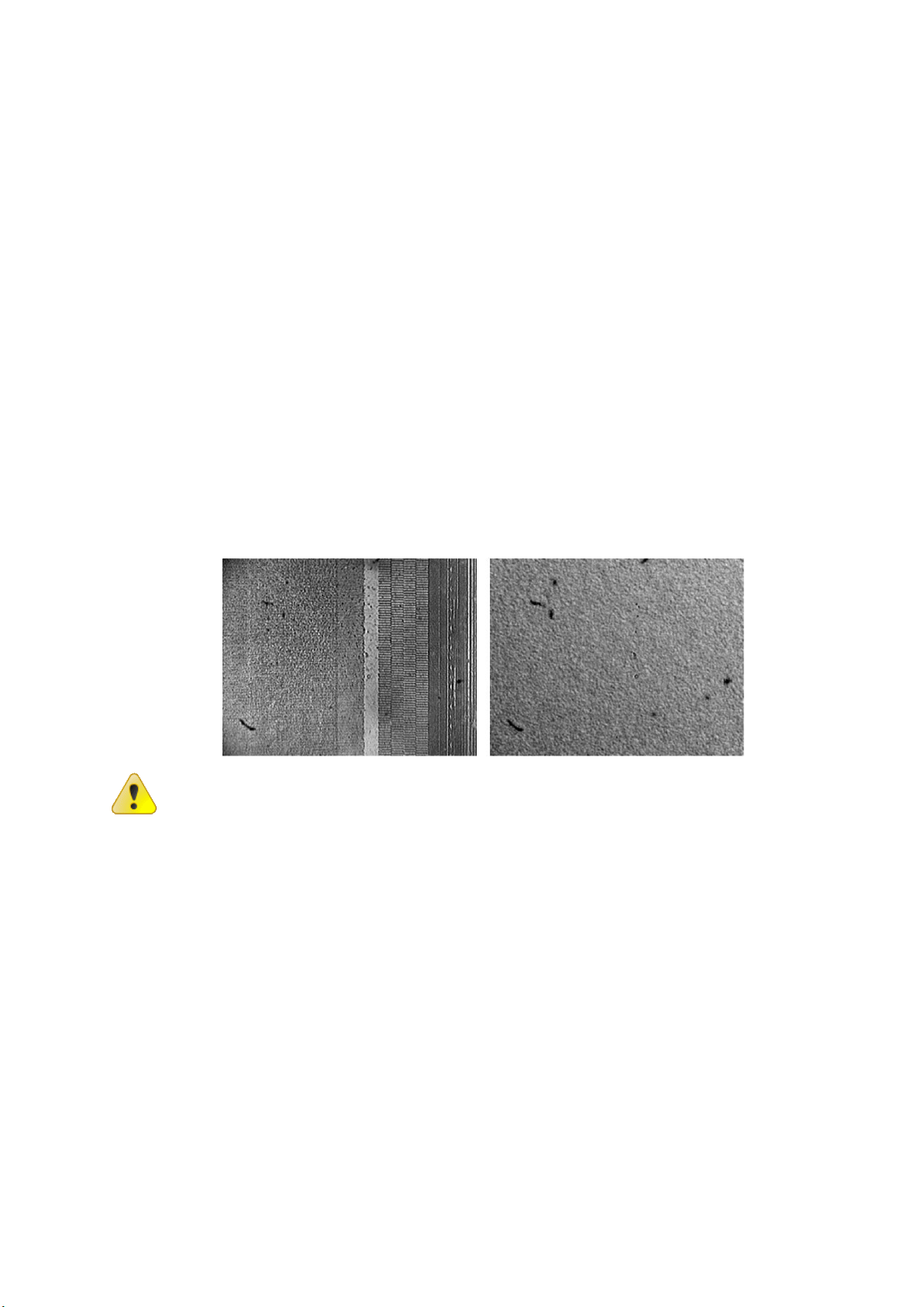
The figure below presents the surface of a HDD in the area of servo marks
before (on the left) and after (on the right) the information erasing by means
of “Kolchuga”.
Further exploitation of HDD after the information erasure is
impossible due to destruction of service information stored on
the medium.
1.4 ABOUT THIS GUIDE
Thank you for purchasing the EPOS Kolchuga. Before the start of device
exploitation, read this manual carefully and save it for reference.
EPOS LLC continuously improves its products. Device specifications and manual
are subject to change without prior notice.

4
2Getting started
2.1 FIRST RUN
The primary installation of the device should be performed without HDDs.
Follow these steps:
1. Connect the wired button;
2. Open the device chassis;
3. Turn on the device UPS (uninterruptable power supply);
4. Close the device chassis;
5. Connect the power cord: first to the device, then to the power supply
outlet;
6. Switch to “Arm” operation mode (depending on your bundle):
Using GSM-module, call the device number and select option “8*”
from the voice menu;
or
Using the button on the back panel of the device.
After switching into “Arm” mode the accelerometer remembers the device
position. For 10 seconds it does not trigger the erasing. After 10 seconds
elapse, the accelerometer becomes active.
7. Experimentally trigger the information erasing without HDDs inside
the device by all available methods (depending on your bundle):
By GSM module: call the device number and select option “6*”
from the voice menu;
By a wireless button: press the big button on the wireless control
unit;
By a wired button: open the protection cap and press the button.
The information erasing is accompanied by a mechanical slap.
It is recommended to run the device during 1-2 weeks in test
mode (without HDDs), before starting the normal exploitation.
2.2 HDD INSTALLATION
1. Switch the device into “Disarm” mode;
2. Disconnect the device from the power supply and unplug the power cord;
3. Open the device chassis;
4. Turn off the device UPS (uninterruptable power supply);
5. To prevent electric injuries, wait for 10 minutes;
6. Depending on your chassis type, remove the power unit or perform the
steps 7-8 for each HDD block;
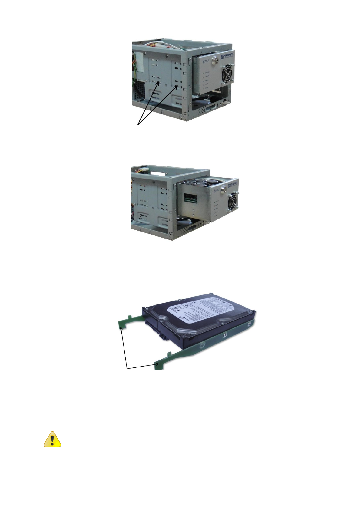
5
7. Remove the screws that hold the HDD block;
8. Pull the HDD block out;
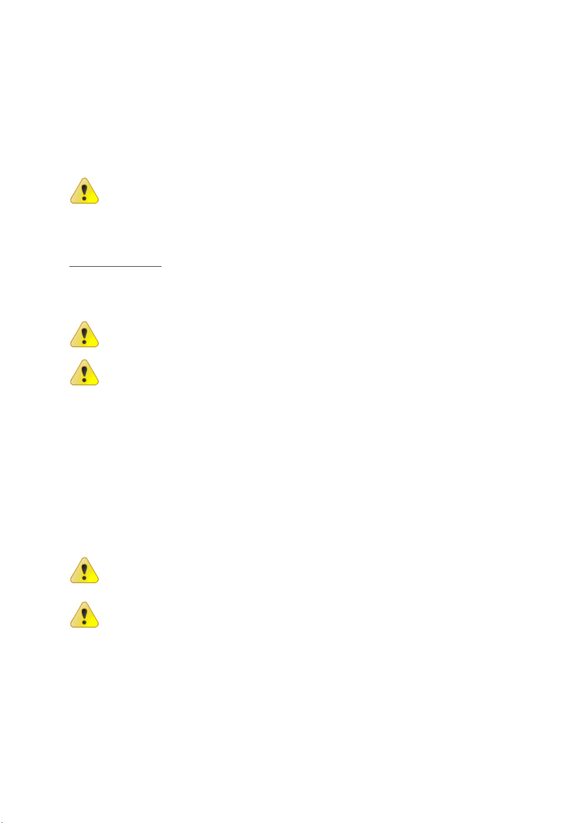
9. Screw on the railing to the HDD and insert the HDD into the processing
chamber of the block until you hear a click;
10. Connect the interface and power cables to the HDD;
11. Assemble the device in reverse order.
After power supply disconnection, electric charge remains in the
device circuits. To prevent electric injuries, do not disassemble
the device untill 10 minutes after the power supply
disconnection.
It is recommended to swithc the device into “Disarm” operation
mode before the power supply disconnection.

6
2.3 GSM MODULE SOFTWARE CONFIGURATION
The device is supplied with pre-configured GSM module software without
access password.
To set the password, configure the GSM module or edit the authorized users
list, use the software and the GSM module guide included on a CD.
You may need to install the GSM module driver (included on a CD) on a
computer to access the GSM module configuration.
To prevent data loss, remove the HDDs from the device before
GSM module reprogramming.
Access to configuration
1. To prevent data loss, remove the HDDs from the device before GSM module
reprogramming;
2. Connect GSM module to a computer (refer to GSM module guide included on
a CD). You may need to install the GSM module driver (included on a CD);
3. Run the GSM module configuration software (included on a CD);
4. Download the microprogram from GSM module using the button “Read” on
the upper toolbar;
5. Edit the settings as needed;
6. Upload the microprogram to GSM module using the button “Program” on the
upper toolbar;
7. Test the new configuration without HDDs: trigger information erasing by
voice call and SMS.
After reconfiguring the GSM module, test the device operation
without HDDs inside the device.
To restore the default settings, upload the default GSM module
microprogram included on a CD

7
GSM password setup
1. Access the GSM module configuration (see the previous paragraph);
2. Using the section tree on the left, switch to the section “Shared
parameters”;
3. In the center of the window, find the group “Security”;
4. Set the new access passwords in fields “SMS User password” and “DTMF
User password”;
5. Enable the checkbox “Apply Administrator password” and set the password
for administrator access and configuration protection.
Authorized users management
Access the GSM module configuration (see the previous paragraph).
Using the section tree on the left, switch between sections “Connection #”,
#=1..8. Each subsection is for one user. The figure below illustrates the user
setup interface for subsection “Connection 1”.
For more information refer to the GSM module guide included on a CD.

8
3Operation modes
3.1 “ARM” MODE
Main operation mode. The device is charged and ready for emergency erasing.
3.2 “DISARM” MODE
The device is inactive. Erasing triggers do not work. Erasing is impossible.
This mode is used for the device maintenance, HDD extraction or replacement,
etc.
It is recommended to backup the data stored in all the HDDs in
the device before maintenance operations.
3.3 SWITCHING THE OPERATION MODES
Switching method depends on your bundle. There are three available methods:
Button on the back panel of the device;
Wireless button (small button on the wireless control unit);
GSM module:
6. Call the device number;
7. Select item 8 in the voice menu;
8. Choose the operation mode:
*- “Arm”;
#- “Disarm”.
When the device enters “Arm” mode, the indicator “Arm” lights up on the front
panel of the device.
After power supply disconnection, electric charge remains in the
device circuits. To prevent electric injuries, do not disassemble
the device untill 10 minutes after the power supply
disconnection.
It is recommended to swithc the device into “Disarm” operation
mode before the power supply disconnection.

9
4Operation
The power switch of the device controls only the power supply to HDDs inside
the device. Power connection / disconnection of the whole device is done by
power cord plugging.
If a device block is installed inside a PC chassis, separate power management
is unavailable.
First turn on the device and power supply of the HDDs, and only
then turn on the PC. Otherwise incorrect HDD detection may
occur.
After turning on the device, the indicators “Power” (Питание) and "Charge"
(Заряд) light up. The coolers turn on. The charging takes not more than 25
seconds. After indicator “Ready”(Готов) is lit, the device is prepared to
operate. Indicator "Charge" (Заряд) blinks in this mode.
In case of an energy accumulation block failure, an indicator “Malfunction”
(Авария) lights up and the information erasing is blocked.
The information erasing is accompanied by a mechanical slap at the moment of
electromagnetic impulse impact. After the erasing, the device switches to
charging mode.
4.1 TRIGGERING BY A KEY
To trigger the information erasing by this method, insert the key into the
keyhole “Erase” and turn it 90° clockwise.
Triggering by a key is possible even when protected HDDs are not powered up.
The device must be in the “Arm” operation mode.
4.2 TRIGGERING BY A WIRED BUTTON (OPTIONAL)
To trigger the information erasing by this method, open the protection cap and
press the button. The device must be in the “Arm” operation mode.
A remote wired button connector may be optionally mounted on the back panel
of the device. Use a button with normally open contact.
Recommended length of a button wire is 25 m. It is recommended to use
shielded cable. In case of using twisted pair cable, it is not recommended to
connect the remote wired button through active network equipment.
Long cable is an antenna that may be affected by interference
induction. In heavy electromagnetic environment this may
falsely trigger the emergency erasing.
It is recommended to test the probability of false triggering
after the device installation in its final place and connection of
the remote wired button BEFORE the HDDs installation.

10
4.3 TRIGGERING BY A WIRELESS BUTTON (OPTIONAL)
To trigger the information erasing by this method, press the big button on the
wireless control unit. The device must be in the “Arm” operation mode.
Wireless control range is up to 100 m in line of sight. Presence of radio
interference may decrease this range.
Radio antenna of the device may be affected by interference
induction. In heavy electromagnetic environment this may
falsely trigger the emergency erasing.
It is recommended to test the wireless control range and
probability of false triggering after the device installation in its
final place BEFORE the HDDs installation.
4.4 TRIGGERING BY A GSM MODULE (OPTIONAL)
Triggering by a GSM module is possible even when protected HDDs are not
powered up. The device must be in the “Arm” operation mode.
The following settings are default. GSM module reprogramming is possible
when necessary or when SIM card is changed. The reprogramming guide is
included on a CD. The basic reprogramming guide is presented below in
section 2.3 “GSM module software configuration”.
Voice menu
DTMF-management of the device resembles the telephone operator service.
Incoming calls are identified by the telephone number. If the user is included
in the authorized users list, he (she) will be offered to enter the password. If
the user is not included in the authorized users list, the call will be rejected.
Thus only the authorized users can access the device management.
If the password is correct, the user enters the main menu and stays in it until
the connection is interrupted. Call is automatically cut, if the user provides no
input for some time or the password is entered incorrectly several times.
Initially, the device enters the “Disarm” mode.
To switch the device into “Arm” mode, dial “8*” when in main menu. Here “8”
is menu item and “*” is “Arm” mode selection.
To switch the device into “Disarm” mode, dial “8#” when in main menu.
To trigger the information erasing by a phone call:
1. Dial the device telephone number;
2. Enter password when prompted;
3. Confirm password by pressing “*”;
4. Dial “6*” to trigger the erasing.
For fast erasing triggering, store the following number in your phonebook.
ХХХХХХХХХХХpYYYY*6*
where ХХХХХХХХХХХ is the telephone number of the device;
p is the pause symbol (For example, in Nokia phones it is entered by repeated
pressing of “*” key. Please refer to your phone manual to know how to enter
the pause symbol. You may have to enter several consequent pause symbols);
YYYY is the password;
* is the password confirmation;
6* is the erasing instruction.
11
SMS
To trigger the erasing by an SMS, send the following message to the device
number:
/YYYYУНИЧТОЖЕНИЕ ВКЛ !
where/is the instruction beginning symbol;
YYYY is the password. There must be no spaces between the symbol “/” and
the password;
УНИЧТОЖЕНИЕВКЛ !is the erasing instruction.
The system is case-sensitive, i.e. “УНИЧТОЖЕНИЕ” and
“уничтожение” are different instructions.
4.5 TRIGGERING BY A CHASSIS INTRUSION SENSOR (OPTIONAL)
The device may be optionally equipped with chassis intrusion sensor (with
normally closed contact). If a device chassis is opened, the information erasing
is triggered.
Triggering by a chassis intrusion sensor is possible even when protected HDDs
are not powered up. The device must be in the “Arm” operation mode.
The sensors are very sensitive. To avoid the false trigerring, it is
recmmended to place the device so that it is not affected by
vibration or not accidentally hit.
It is recommended to test the probability of false triggering
after the device installation in its final place BEFORE the HDDs
installation.
4.6 TRIGGERING BY AN ACCELEROMETER (OPTIONAL)
The device may be optionally equipped with motion sensor based on 3-axis
accelerometer. Mounted inside the device chassis, the sensor detects device
displacement and triggers the erasing.
After switching into “Arm” mode the accelerometer remembers the device
position. For 10 seconds it does not trigger the erasing. After 10 seconds
elapse, the accelerometer becomes active.
Triggering by an accelerometer is possible even when protected HDDs are not
powered up. The device must be in the “Arm” operation mode.
The accelerometer is very sensitive. To avoid the false
trigerring, it is recmmended to place the device so that it is not
affected by vibration or not accidentally hit. Do not place the
device on inclined or uneven surfaces.
It is recommended to test the probability of false triggering
after the device installation in its final place BEFORE the HDDs
installation.

12
4.7 EVENT NOTIFICATION
Notification is done by sending SMS to all authorized users.
By default, the device notifies about information erasing and power supply
status changes.
The following settings are default. GSM module reprogramming is possible
when necessary or when SIM card is changed. The reprogramming guide is
included on a CD. The basic reprogramming guide is presented below in
section 2.3 “GSM module software configuration”.
Triggered by a key
After erasing the information on all the protected HDDs, the device sends the
following messages to all the authorized users:
<<time>>
КЛЮЧ ON
where <<time>>is the erasing triggering time;
КЛЮЧ ON is the key triggering report.
Triggered by a wired button
After erasing the information on all the protected HDDs, the device sends the
following messages to all the authorized users:
<<time>>
ВН.КНОПКА ON
where <<time>>is the erasing triggering time;
ВН.КНОПКА ON is the wired button triggering report.
Triggered by a wireless button
After erasing the information on all the protected HDDs, the device sends the
following messages to all the authorized users:
<<time>>
РАДИО_БР ON
where <<time>>is the erasing triggering time;
РАДИО_БР ON is the wireless button triggering report.
Triggered by a GSM module
After erasing the information on all the protected HDDs, the device sends the
following messages to all the authorized users:
<<time>>
ВЫХОД УНИЧТОЖЕНИЕ ВКЛ
where <<time>>is the erasing triggering time;
ВЫХОД УНИЧТОЖЕНИЕ ВКЛ is the GSM module triggering report.
Triggered by a chassis intrusion sensor
After erasing the information on all the protected HDDs, the device sends the
following messages to all the authorized users:
<<time>>
КОРПУС ОТКРЫТ
where <<time>>is the erasing triggering time;
КОРПУС ОТКРЫТ is the chassis intrusion sensor triggering report.

13
Triggered by an accelerometer
After erasing the information on all the protected HDDs, the device sends the
following messages to all the authorized users:
<<time>>
НАКЛОН ON
where <<time>>is the erasing triggering time;
НАКЛОН ON is the accelerometer triggering report.
Power loss
The GPS module is equipped with an accumulator battery.
In case of external power loss, the device sends the following messages to all
the authorized users:
<<time>>
ЗАРЯД-MIN
where <<time>>is the power loss time;
ЗАРЯД-MIN –is the power loss report.
Upon power restoration, the device sends the following messages to all the
authorized users:
<<time>>
ПИТАНИЕ ОК
where <<time>>is the power restoration time;
ПИТАНИЕ ОК is the power restoration report.
Upon accumulator battery discharge to 40% of its capacity, the device sends
the following messages to all the authorized users:
<<time>>
АКБ 40%
where <<time>>is the battery level detection time;
АКБ 40% is the battery discharge report.
Upon accumulator battery discharge to 20% of its capacity, the device sends
the following messages to all the authorized users:
<<time>>
АКБ 20%
where <<time>>is the battery level detection time;
АКБ 20% is the battery discharge report.
Upon complete accumulator battery discharge, the device controller shuts
down and erasing becomes impossible.
Malfunction
In case of malfunction detection, the device sends the following messages to
all the authorized users:
<<time>>
АВАРИЯ ОN
where <<time>>is the malfunction detection time;
АВАРИЯОN is the malfunction report.

14
5Exploitation rules
5.1 GENERAL RULES
Never trigger the information erasing until the device is completely charged
(indicator “Ready” (Готов) lights up). Otherwise, reliable information
destruction is not guaranteed.
Never use the device when the indicator “Malfunction” (Авария) lights up.
Daily backup of all the data stored in the device to external storage is
recommended.
It is recommended to backup the data stored in all the HDDs in the device
before maintenance operations.
HDD should be installed after the device testing in its final place.
If the device is powered up while being in “Arm” mode, the failure is possible.
In this case, the indicator “Malfunction” lights up and the beep is played. To
reset the device in this case, switch the operation mode to “Disarm”, turn the
device power off and on again and finally, switch the operation mode to “Arm”.
5.2 OPERATIONAL ENVIRONMENT
The device is designed for exploitation indoors with the following environment
characteristics:
Surrounding air temperature: +5 °C … +40 °C;
Relative humidity ≤ 80%;
Dust level ≤ 0,75 mg/m³;
The air must not contain vapors of aggressive liquids and
substances causing corrosion.
5.3 MAINTENANCE
The device “Kolchuga” should pass yearly tests, which are performed at the
Computer forensics and information security laboratory of "EPOS” LLC.
Address: 44, Verkhniy Val str., Kiev, 04071, Ukraine.
5.4 DEVICE STORAGE
To prepare the device for long-term storage, disconnect all the power supply
components, including uninterruptable power supply unit and GSM module
accumulator.
To bring the device back into service, perform the operations listed in section
2.1 “First run”.

15
6Troubleshooting
Problem:
Indicator “Malfunction” (Авария) glows on one or several device blocks. The
device sends the following messages to all the authorized users:
АВАРИЯ ОN
Probable reason:
The device was powered up while being in “Arm” mode.
Solution:
Reset the device:
1. Switch the operation mode to “Disarm”;
2. Turn the device power off and on again;
3. Switch the operation mode to “Arm”.
Problem:
After switching to “Arm” mode the device does not get ready (the indicator
“Ready” (Готов) does not light up), but indicators “Power” (Питание) and
“Charge” (Заряд) glow.
Probable reason:
Chassis intrusion sensor is open.
Solution:
1. Disconnect the device from the power supply and unplug the power cord;
2. Check whether the chassis cover is closed correctly and firmly;
3. Power up the device.
In case a problem occurs continuously or another problem happens, contact
the Computer forensics and information security laboratory of "EPOS” LLC.
Address: 44, Verkhniy Val str., Kiev, 04071, Ukraine.
Tel.: +380 (44) 425-23-42
Skype: procd.ua
Table of contents
Popular Storage manuals by other brands

Silicon Graphics
Silicon Graphics InfiniteStorage 350 quick start guide

NETGEAR
NETGEAR SC101 - Storage Central NAS Server Revised Troubleshooting Guide

Petastor
Petastor AN-824STS Hardware installation guide

Seagate
Seagate ST310014ACE - U Series X 10 GB Hard Drive product manual

HP
HP StorageWorks 4000/6000/8000 - Enterprise Virtual... release note

Transcend
Transcend StoreJet 35T3 user manual


ATTO Technology
ATTO Technology FastStream SC 5500 Installation and operation manual

EXP Computer
EXP Computer HD Traveler Plus PCMCIA installation guide

Spectra Logic
Spectra Logic Spectra 64K supplementary guide

VERITAS
VERITAS 5U84 Service Procedure

SanDisk
SanDisk TrustedSignins brochure

Hitachi
Hitachi Travelstar 7K60 Quick installation guide