EPRAD LCS User manual

LCS & LDP
LED Light Dimming System
Manual
Version 1.4 Nov 19, 2020

EPRAD Incorporated
28271 Cedar Park Blvd
Perrysburg, O 43551 USA
P : 419-666-3266
Warranty
Light dimmer products, sold by EPRAD Incorporated, are warranted against defects in materials and
workmanship for one year from the date of purchase. There are no other express or implied
warranties and no warranty of merchantability or fitness for a particular purpose.
During the warranty period, EPRAD Incorporated will repair or, at its option, replace components that
prove to be defective, provided the unit is shipped prepaid to the manufacturer directly or via an
authorized distributor. Not covered by this warranty are defects caused by modification, misuse or
accidents and any further damage caused by inadequate packing for service return.
EPRAD Incorporated’s obligation is restricted to the repair or replacement of defective parts and
under no circumstances will EPRAD Incorporated be liable for any other damage, either direct or
consequential.
Trademark Notice
All trademarks referenced in this document and in the product software are the sole property of their
respective owners. EPRAD Incorporated is in no way affiliated with the owners of the trademarks. The
information contained in this document is provided by EPRAD solely to assist the users of EPRAD
products in interfacing with third party cinema equipment. EPRAD assumes no responsibility for any
discrepancies or inaccuracies in the information provided in this document as third party products are
beyond the control of EPRAD Incorporated.
Information in this document is subject to change without notice. No part of this document may be
reproduced or transmitted in any form or by any means, electronic or mechanical, for any purpose,
without the express written permission of EPRAD Incorporated.
© 2020 EPRAD INC. All right re erved.

EPRAD Incorporated LED Light Dimming System PATENT PENDING
When using electrical equipment, basic safety precautions should always be followed
including the following:
READ AND FOLLOW ALL SAFETY INSTRUCTIONS
1. Do not use outdoors.
2. Do not mount near gas or electric heaters.
3. Equipment should be mounted in locations and heights where it will not readily
be subjected to tampering by unauthorized personnel.
4. The use of accessory equipment not recommended by the manufacturer may
cause an unsafe condition.
5. Do not use this equipment for other than intended use.
6. Refer service to qualified personnel.
SAVE THESE INSTRUCTIONS
WARNING: You must have access to a main circuit breaker or other power
disconnect device before installing any wiring. Installing the device with power on
may expose you to dangerous voltage and damage the device. A qualified
electrician must perform this installation.
WARNING: If replacing the fuse in this unit, you must replace fuse with exact
same type and rating.
WARNING: Refer to National Electrical Code® and local codes for cable
specifications. Failure to use proper cable can result in damage to equipment or
danger to persons.
WARNING: This equipment is intended for installation in accordance with the
National Electric Code® and local regulations. It is also intended for permanent
installation in indoor applications only. Before any electrical work is performed,
disconnect power at the circuit breaker or remove the fuse to avoid shock or
damage to the control. It is recommended that a qualified electrician perform this
installation.
CAUTION: Wire openings must have fittings or lining to protect wires/cables
from damage. Use 90° C copper wire only.
IMPORTANT SAFEGUARDS
Page 1 of 32

EPRAD Incorporated LED Light Dimming System PATENT PENDING
Safety and Regulatory Approval
Complies with the following regulatory standards for product safety and emergency lighting:
• Industrial Control Equipment [UL 508:2018 Ed.18]
• Industrial Control Equipment [CSA C22.2#14:2018 Ed.13]
• Standard For Emergency Lighting And Power Equipment [UL 924:2016 Ed.10+R:08Mar2017]
• Emergency Lighting Equipment [CSA C22.2#141:2015 Ed.5]
Safety Indication on the Product
This symbol is intended to alert the
operator that parts inside this
cabinet may involve risk of electric
shock.
This symbol is intended to alert the
operator to the presence of
important operating and servicing
instructions in technical
documentation for this equipment.
Page 2 of 32

EPRAD Incorporated LED Light Dimming System PATENT PENDING
Content
• Overview
• QDC-400 Dimmer Control Board
• LED Dimmer Power Module
• Emergency Lighting Operation (UL 924)
• In tallation
• Setup
• Manual Control Key
• U ing the LCS Dimmer with the eCNA Automation
• LED Lamp
• Serie Voltage Drop of Luminarie
• Model Number
Page 3 of 32
EPRAD Incorporated LED Light Dimming System PATENT PENDING
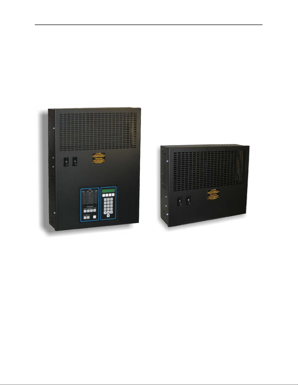
Overview
The LCS and LDP series LED light dimmers are designed to control EPRAD 36 Volt
LED lamps. They can be integrated with any cinema automation system to create
lighting effects in the auditorium. The standard unit is available as either a 1 or 2
channel configuration of either 200 or 320 watts per channel. The number of
channels can be expanded to 4 with the addition of the LDP LED dimmer expansion
unit. Each channel can be configured for any light zone with independent levels and
fade times. EPRAD LED lamps are standard profile with a medium screw-in base in
order to utilize existing lamps fixtures.
LSC LED Dimmer LDP LED Dimmer
The LCS dimmer consists of the QDC-400 control board and one or two LDD-36V
LED power modules.
The LDP LED dimmer cabinet is available in three base models with one or two
LDD-36V LED power modules:
• The LDP Expansion unit is used to expand the number of channels to the LCS
dimmer.
• The LDP Conversion unit can be used with existing phase-cut dimmers to
provide compatibility with EPRAD LED lamps.
• The LDP DC Control unit can be used with existing 0-10V dimmer controllers to
provide compatibility with EPRAD LED lamps.
Page 4 of 32
EPRAD Incorporated LED Light Dimming System PATENT PENDING
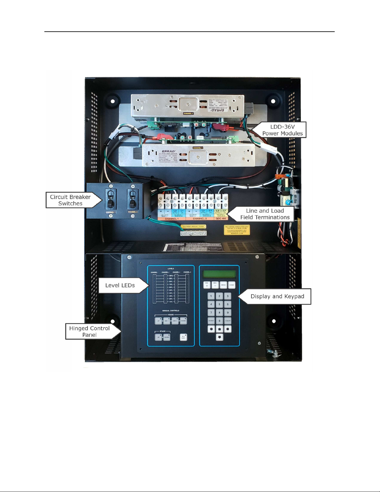
LCS Internals
Page 5 of 32

EPRAD Incorporated LED Light Dimming System PATENT PENDING
LDP Internals
Page 6 of 32
EPRAD Incorporated LED Light Dimming System PATENT PENDING
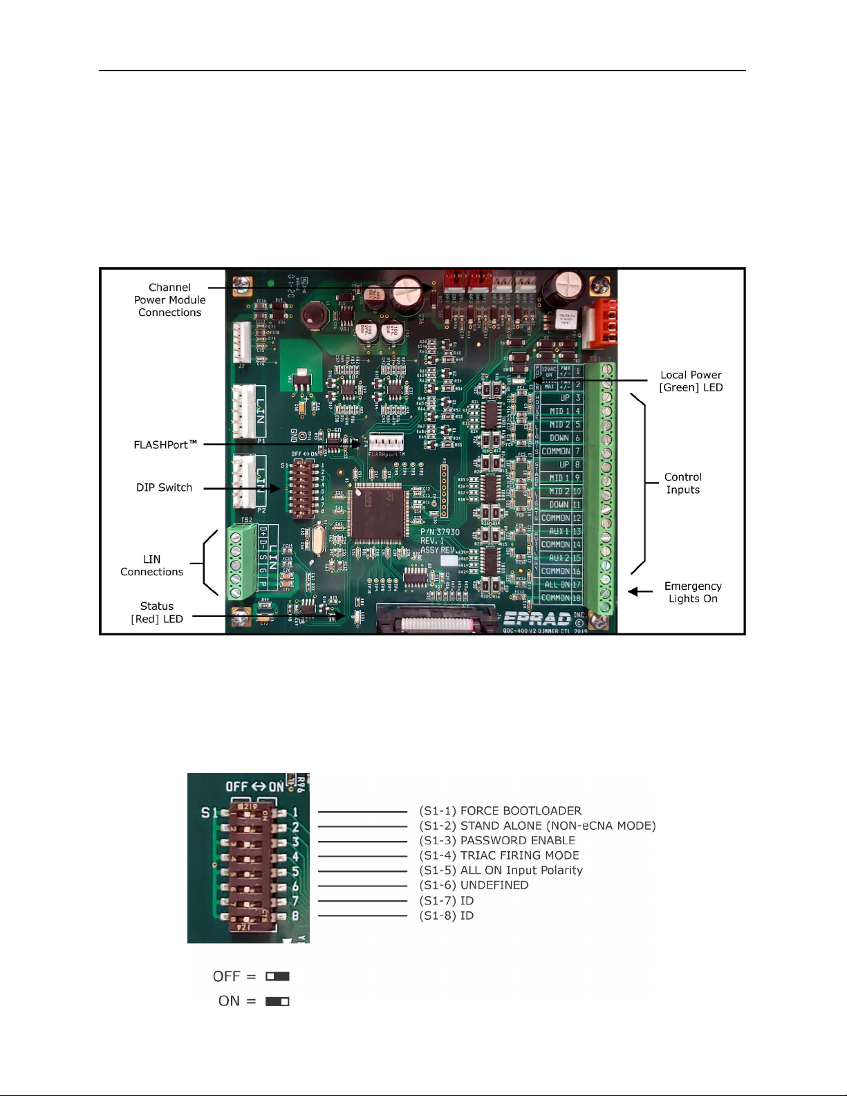
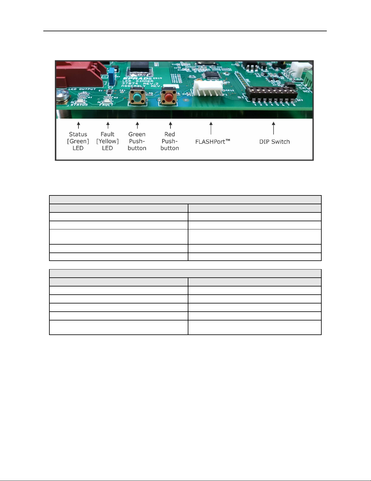
QDC-400 Dimmer Control Board
The QDC-400 is a four channel light dimmer controller. Light levels for each channel
are saved both locally and at the eCNA. Each level can be set from 0% to 100% in
1% increments. Each level has a Fade-In time that time controls how long it takes
the lights to ramp to a new level. The Fade-In time can be set from 0 to 99 seconds
with 1 second resolution. The channels can be independently configured for any of
sixteen zones. The LDD-36V LED dimmer module receives the level and fade time
from the QDC-400 control board to control EPRAD 36VDC LED lamps.
Note: The QDC-400 control board receives power from multiple sources: The LIN, the power modules
and the local power supply. The board can operate from any of these power sources, but only the
local power supply is large enough to power the level LEDs and LCD backlight.
1. DIP Switch Setting
DIP Switch Definitions
Page 7 of 32

EPRAD Incorporated LED Light Dimming System PATENT PENDING
S1 ON OFF
1 Force Boot Loader Normal Use (Default)
2 Stand Alone Mode eCNA Mode - Communicates with the eCNA
via LIN
3 Password Disabled Password Enabled (Default)
4 Triac gate is held on until just before
zero-cross
Triac gate is pulsed
5 ALL ON Input igh ALL ON Input Low
6 Not Defined
The eCNA Local I/O Network (LIN) can support up to 32 devices. Each of these devices requires a unique ID
number. IDs 13 through 16 are reserved for the QDC-400 control board. The ID must be set correctly. The ID
number determines which channel configuration or control record data the QDC-400 will use. ID switches are
ignored in Stand Alone mode.
S1 ID = 13
(Channels 1 - 4)
ID = 14
(Channels 5 - 8)
ID = 15
(Channels 9 - 12)
ID = 16
(Channels 13 - 16)
7 OFF OFF ON ON
8 OFF ON OFF ON
2. Statu LED
The RED Status LED on the QDC-400 control board indicates the following
conditions:
Statu LED
Statu Condition
Fast Blink The QDC-400 computer is working and is communicating properly with the
CNA.
1 Blink On,
Pause 2 seconds
The QDC-400 computer is waiting for data from the CNA, and the outputs
are disabled. This condition indicates that since a power up, the QDC-400
has not received data from the CNA. The lights are off and QDC-400 will
wait indefinitely for communications to be established.
2 Blinks On,
Pause 2 seconds
Communications Timeout, outputs are disabled. This condition indicates
that communications were once established to the CNA and subsequently
lost. The lights are off.
3 Blinks On,
Pause 2 seconds
Communications Timeout, outputs are held. This condition indicates that
communications were once established to the CNA and subsequently lost.
The lights hold their current output level. The local Stage and ouse
overrides will ramp outputs to the new level.
4 Blinks On,
Pause 2 seconds
Running BOOT LOADER program. The Boot loader program should only be
running if the ‘force bootloader’ switch is on or the a ‘Flash’ program
upgrade is in process.
5 Blinks On, Pause
2 seconds
The QDC-400 is running in ‘Stand Alone’ mode. DIP switch S1-2 is on.
3. Local Power LED
The GREEN Status LED indicates the local power supply is on.
Page 8 of 32

EPRAD Incorporated LED Light Dimming System PATENT PENDING
4. Channel Power Module Connection
These connections are used to provide control data (level and fade-in time) to the
power modules and power to the QDC-400 control board.
5. LIN Connection
LIN (Local I/O Network) connection from the eCNA automation. The LIN is a 5 wire
connection that contains both DC power and data (RS485). See LCS Field Wiring.
6. Control Input
These inputs are used to connect the cinema automation or manual override
switches to select the presets for the ouse and Stage lights. A dry contact closure
is required. See LCS Field Wiring.
7. Emergency On
A dry contact closure between the ALL ON and COMMON input ramps all channels
to 100%. See LCS Field Wiring.
8. Fla hPortTM
The FlashPortTM is used to upgrade the QDC-400 firmware using the EPRAD PROG-
10 Programming Adapter.
Page 9 of 32
EPRAD Incorporated LED Light Dimming System PATENT PENDING
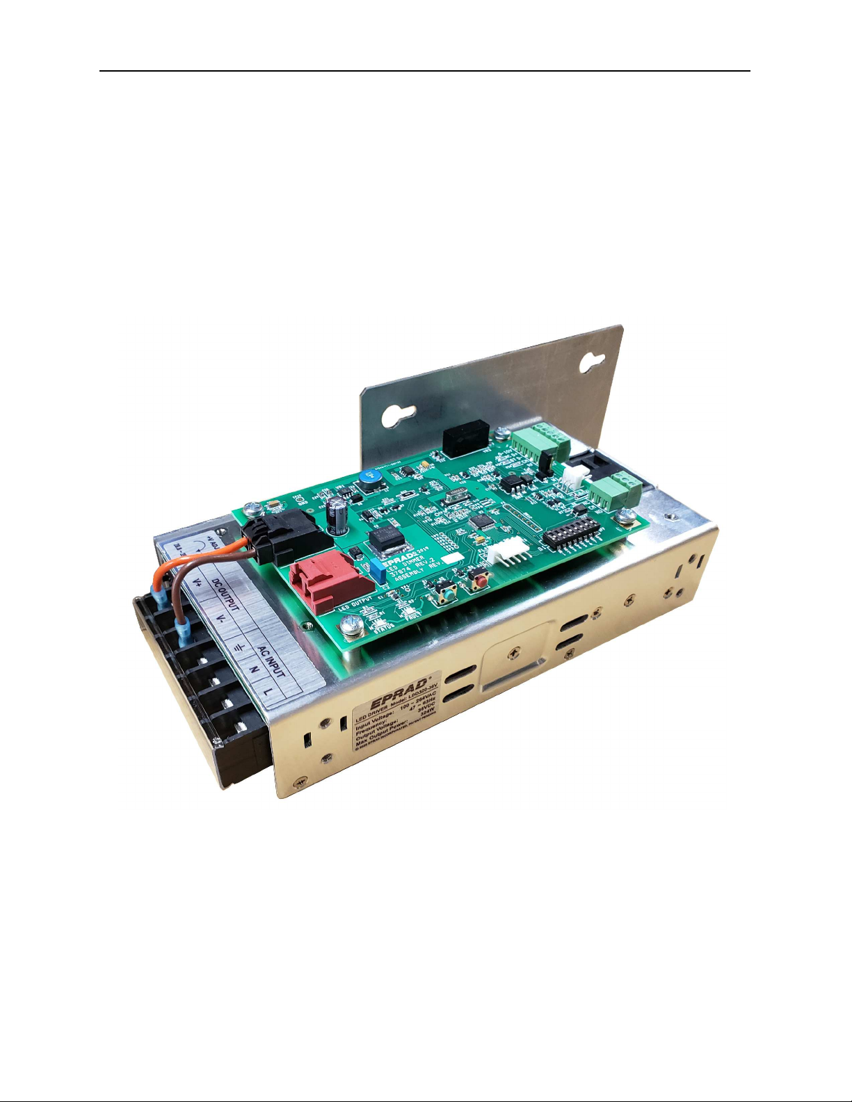
LED Dimmer Power Module
The LDD-36V LED dimmer module is available in 320 and 200 watt versions. Models
LDD320-36V and LDD200-36V, respectively.
• Regulated 36 volts PWM output
• 3-way isolation: Power-to-Load, Power-to-Control and Control-to-Load
• Active Power Factor Correction
• Over-current and Short Circuit Protection
• QDC-400 and 0-10V Control Inputs
• Emergency Lights On (Bypass) Input
LDD320-36V Dimmer Power Module
Page 10 of 32
EPRAD Incorporated LED Light Dimming System PATENT PENDING
Status and Configuration
The dimmer power module has 2 LEDs to indicate the current status of the module.
Green Statu LED
Statu Condition
Off No power (or processor not running).
Slow Blink (1 Second On, 1 Second Off) Not receiving command data from QDC-400.
Fast Blink (125 Milliseconds On, 125
Milliseconds off)
Ok - Receiving command data from QDC-400
2 Blinks on, pause 1 second Ok - 0-10V Control Mode
4 Blinks on, pause 1 second Boot Loader running
Yellow Fault LED
Statu Condition
Off Ok (No fault conditions present)
2 Blinks on, pause 1 second Over Current Fault
3 Blinks on, pause 1 second Under Voltage Fault
4 Blinks on, pause 1 second Over Current and Under Voltage Fault
Fast Blink (250 Milliseconds On, 250
Milliseconds off)
Over Current and Under Voltage Faults
disabled (S1-8 = On)
The Faults are “Latched” until they are manually reset. While a Fault is active, the
module will not provide power to the connected lights.
The Fault conditions can be manually reset one of two ways:
• Turn Power Off then back on.
• Set the Light Level Set Point to 0%.
Note: The “Under Voltage Fault” won’t reset when the “Under Voltage Condition” is
still present.
Page 11 of 32

EPRAD Incorporated LED Light Dimming System PATENT PENDING
DIP Switch
S1 ON OFF
1 Force Boot Loader Normal Use (Default)
2 0-10V Control Mode QDC-400 Control Mode
3 Not Defined
4 Not Defined
5 Not Defined
6 Not Defined
7 Not Defined
8 Over-current and Under Voltage
Faults disabled
Over-current and Under Voltage Faults
enabled
0-10V Input Calibration
The 0-10V analog input needs to be calibrated to match your dimmer controller’s
output. This is to make sure the minimum and maximum levels of the dimmer
controller correspond to 0% and 100% light level. The values are saved to
EEPROM.
1. Press and hold the Green pushbutton switch for 5 seconds until the Yellow LED
turns on.
2. Set the level of the attached dimmer controller to 0% level. Press the Green
pushbutton. The Yellow LED blinks slowly.
3. Set the level of the attached dimmer controller to 100% level. Press the Green
pushbutton. The Yellow LED turns off. The calibration is complete.
Fla hPortTM
The FlashPortTM is used to upgrade the LDD-36V firmware using the EPRAD
PROG-10 Programming Adapter.
Page 12 of 32
EPRAD Incorporated LED Light Dimming System PATENT PENDING
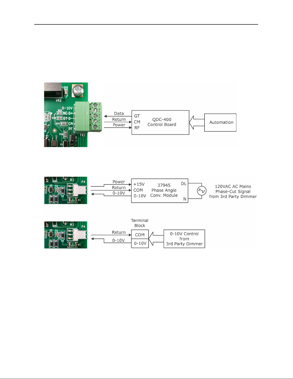
Power Module Control Input
The level control inputs are wired internally to the QDC-400 control board on the
LCS model or field termination points (terminal block) on the LDP models.
The module can receive its level information from a serial data stream from the
QDC-400 control board on TB2.
The module can accept a 0 to 10 volt signal from a controller on P4 as shown.
Page 13 of 32
EPRAD Incorporated LED Light Dimming System PATENT PENDING
LED Power Module
Emergency Bypass Connection
QDC-400 Emergency Bypass Connection
Emergency Lighting Operation (UL 924)
When required, the LCS and LDP dimmer panels can be used as part of the
emergency lighting circuit when the normal lights are also used as emergency
lights. Both the QDC-400 control board and the LED dimmer power modules have a
dedicated emergency input that will energize the lights to 100%, bypassing the
current light level. As long as this input is maintained the lights will remain at
100%, regardless of any other control input.
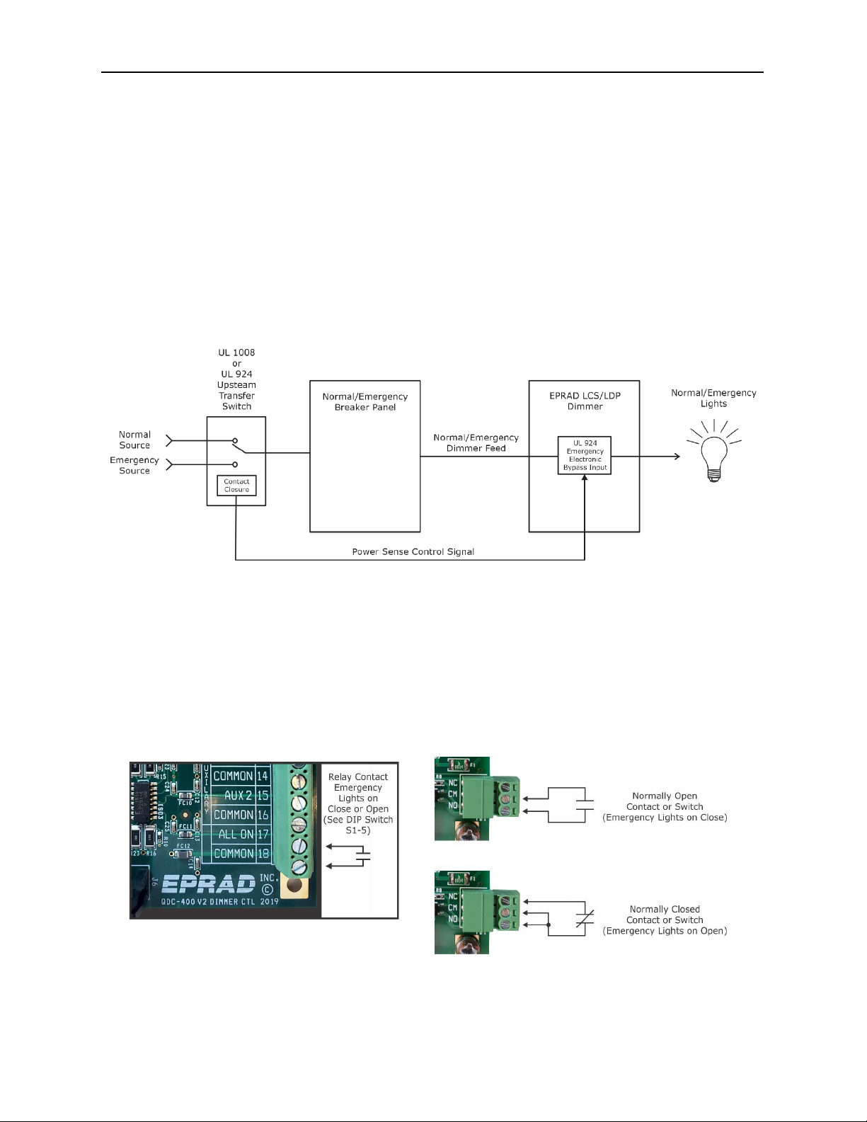
When the LCS or LDP are used as part of the emergency lighting system, the power
supplied to the dimmer must switched by an upstream UL 1008 or UL 924 transfer
switch with a phase loss relay interface to monitor normal power and provide a
control signal to the dimmer in the event of a disruption in power.
The emergency input on the LED dimmer power modules can be used to bypass
individual light dimmer channels. The emergency input on the QDC-400 control
board can be used to bypass all channels. See the field wiring diagrams for wiring
the emergency inputs on the QDC-400 and the LED dimmer power module.
Page 14 of 32
EPRAD Incorporated LED Light Dimming System PATENT PENDING
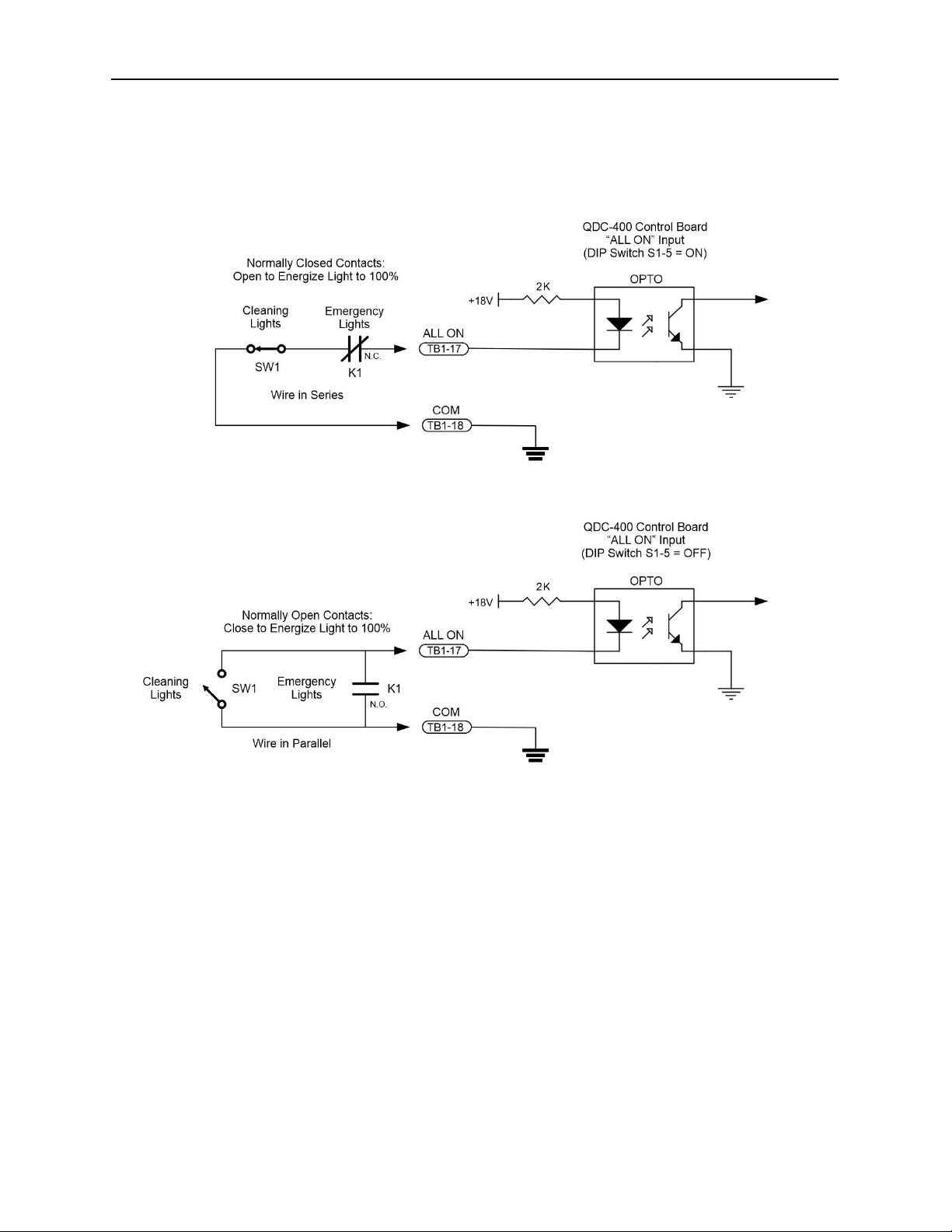
The emergency input on the QDC-400 control board can also be used to activate
the lights for cleaning. When using this input for both cleaning and emergency
purposes, the phase loss sensing relay and the cleaning lights switch can be wired
in one of two ways depending on the contact configuration of the phase loss relay.
Page 15 of 32
EPRAD Incorporated LED Light Dimming System PATENT PENDING
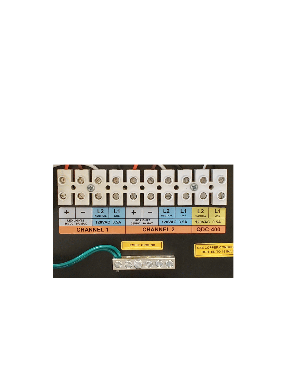
In tallation
An appropriate sized supply line should be connected to the terminals identified as
L1 and L2. L1 being the Line wire and L2 being the Neutral wire.
An appropriate sized load line should be connected to the 36VDC + and - terminals.
The LED lights must not be connected to mains power (line or neutral). It is best
that the low voltage LED lamp wiring be routed away from electrically noisy
conductors or equipment.
NOTE: The LED lamps can tolerate a voltage drop of up to 25%, however it is
prudent to estimate or calculate the expected voltage drop at the last lamp.
Because the current varies along the circuit, the procedure for calculating the
voltage drop at the end of a string of lights can be tedious. While rules-of-thumb
may be applied, they do not always give the desired confidence. The Electrical
Designer’s Reference software makes the calculations easy. See the Serie
Voltage Drop section.
For successful operation and safety, the cabinet should be properly grounded in
accordance to local electrical code requirements.
Power Wiring Terminal Block
Page 16 of 32

EPRAD Incorporated LED Light Dimming System PATENT PENDING
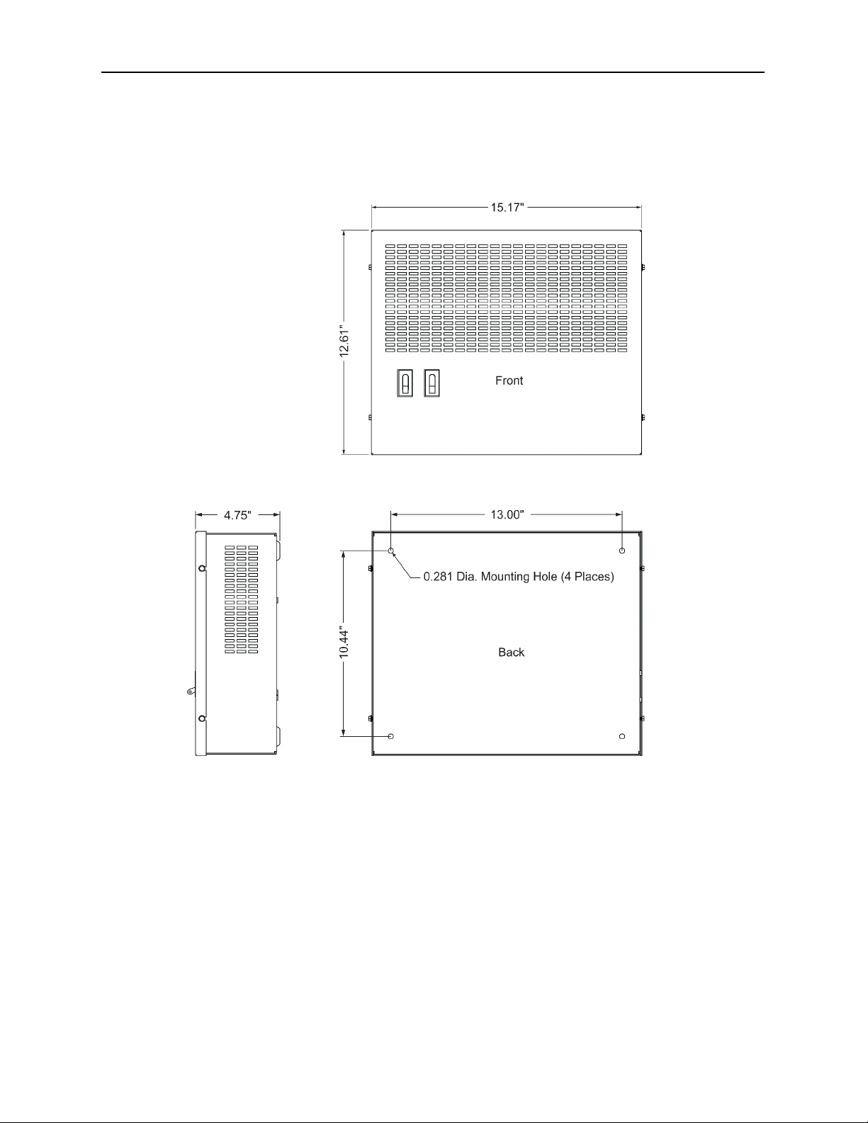
LCS Cabinet Dimensions
Page 17 of 32
EPRAD Incorporated LED Light Dimming System PATENT PENDING
LDP Cabinet Dimensions
Page 18 of 32
This manual suits for next models
1
Table of contents
Other EPRAD Home Theater System manuals


