EPRAD eCNA-10 User manual

Model eCNA-10
D-Cinema Automation
Installation and Operation
Manual
Version 1.270-00 January 5, 2021


EPRAD Incorporated
28271 Cedar Park Blvd
Perrysburg, O io 43551 USA
Telep one 419-666-3266
www.eprad.com
Warranty
Automation products, sold by EPRAD Incorporated, are warranted against defects in materials and
workmans ip for one year from t e date of purc ase. T ere are no ot er express or implied
warranties and no warranty of merc antability or fitness for a particular purpose.
During t e warranty period, EPRAD Incorporated will repair or, at its option, replace components t at
prove to be defective, provided t e unit is s ipped prepaid to t e manufacturer directly or via an
aut orized distributor. Not covered by t is warranty are defects caused by modification, misuse or
accidents and any furt er damage caused by inadequate packing for service return.
EPRAD Incorporated’s obligation is restricted to t e repair or replacement of defective parts and
under no circumstances will EPRAD Incorporated be liable for any ot er damage, eit er direct or
consequential.
Trademark Notice
All trademarks referenced in t is document and in t e product software are t e sole property of t eir
respective owners. EPRAD Incorporated is in no way affiliated wit t e owners of t e trademarks. T e
information contained in t is document is provided by EPRAD solely to assist t e users of EPRAD
products in interfacing wit t ird party cinema equipment. EPRAD assumes no responsibility for any
discrepancies or inaccuracies in t e information provided in t is document as t ird party products are
beyond t e control of EPRAD Incorporated.
Information in t is document is subject to c ange wit out notice. No part of t is document may be
reproduced or transmitted in any form or by any means, electronic or mec anical, for any purpose,
wit out t e express written permission of EPRAD Incorporated.
© EPRAD Incorporated, 2020
i
eCNA-10 Operation and Installation Man al Version 1.270-00

Safety and Reg latory Approvals
Conforms to ANSI/UL Standard 60950-1
Certified to CSA Standard C22.2 No. 60950-1
IECEE CB SCHEME Certified
Complies wit t e following regulatory standards for product safety, electromagnetic compatibility
(EMC) and environmental requirements:
IEC 60950-1: 2005 (2nd Edition)
EMC Directive 2004/108/EC
IEC/CISPR 22: 1997, +A1: 2000, +A2: 2002
IEC/CISPR 24: 1997, +A1: 2001, +A2: 2002
EN 55022: 1998, +A1: 2000, +A2: 2003
EN 55024: 1998, +A1: 2001, +A2: 2003
FCC CFR47 Part 15
AS/NZS CISPR22: 2004
ICES-003, Issue-4
ETL Listed, File No. 3161934
Safety Statement
T is equipment is manufactured in accordance wit t e requirements of t e international standard
IEC60950-1, ICES-003 Class A, EN 55022:95, IEC61000. T ese safety standards impose important
requirements on t e use of critical safety components, materials, and isolation in order to protect t e
user or operator from risk of electric s ock. It is t erefore important to fully comply wit t e
instructions found in t e safety and installation document (PR021S Rev. 0) included wit t e
equipment.
Installation Instr ctions
#Before installing, operating, or servicing t is equipment, read t is manual t oroug ly and retain it
for future reference
#Installation s ould only be performed by qualified personnel
#All warnings and precautionary statements on t e eCNA-10 and ot er system devices as well as in
t e accompanying documentation must be observed
#All instructions for operating t is equipment must be followed precisely
Safety Indication on the Prod ct
T is symbol is intended to alert t e
operator t at parts inside t is cabinet
may involve risk of electrical s ock.
T is symbol is intended to alert t e
operator to t e presence of important
operating and servicing instructions in
tec nical documentation for t is
equipment.
ii eCNA-10 Operation and Installation Man al Version 1.270-00

Table of Contents
1. Prod ct Description .................................................. 1
2. Control Panel ....................................................... 2
3. Display Screen ...................................................... 3
3.1 Power Up Screen ................................................. 3
3.2 Top Level Screens ................................................ 4
3.2.1 Run Status Screen .......................................... 4
3.2.2 Output Screen ............................................. 5
3.3 Menu Screens ................................................... 5
3.3.1 Network Status Screen ....................................... 5
3.3.2 Et ernet TCP/IP Screens ...................................... 7
3.3.3 User-Defined Keys Screen ..................................... 8
3.3.4 Dimmer Screens ............................................ 8
3.3.5 Information Screen .......................................... 9
3.3.6 Status and Fault Messages . . . . . . . . . . . . . . . . . . . . . . . . . . . . . . . . . . . . 9
4. Config ring the Unit ................................................. 11
4.1 Configuring t e Main CPU Board . . . . . . . . . . . . . . . . . . . . . . . . . . . . . . . . . . . . . . 11
4.2 Configuring Et ernet via t e Serial Port . . . . . . . . . . . . . . . . . . . . . . . . . . . . . . . . . 15
4.3 Configuring via t e Web Browser . . . . . . . . . . . . . . . . . . . . . . . . . . . . . . . . . . . . . . 18
4.3.1 Setup ...................................................19
4.3.2 Setup: Et ernet Network ......................................19
4.3.3 Setup: Wake-On-LAN ........................................21
4.3.4 Setup: Triggers ............................................22
4.3.5 Setup: Fault Be avior ........................................25
4.3.6 Setup: Real Time Clock .......................................27
4.3.7 Setup: System Parameters . . . . . . . . . . . . . . . . . . . . . . . . . . . . . . . . . . . . 28
4.3.8 Setup: Segment Names.......................................33
4.3.9 Setup: Output Flag Names . . . . . . . . . . . . . . . . . . . . . . . . . . . . . . . . . . . . 34
4.3.10 Setup: Input Flag Names . . . . . . . . . . . . . . . . . . . . . . . . . . . . . . . . . . . . 35
4.3.11 Setup: CAI SendFx Names . . . . . . . . . . . . . . . . . . . . . . . . . . . . . . . . . . . 36
4.3.12 Setup: User Key Names .....................................37
4.3.13 Setup: Timer Names ........................................38
4.3.14 Setup: Remote Devices ......................................39
4.3.15 Setup: Clock Events ........................................43
4.3.16 Setup: Virtual I/O .........................................44
4.3.17 I/O Boards ...............................................46
4.3.18 Setup: 39431/39445 House/Aux . . . . . . . . . . . . . . . . . . . . . . . . . . . . . . . . 47
4.3.19 Setup: Lig t Control ........................................51
4.3.20 Setup: Zone Names ........................................51
4.3.21 Setup: QDC-400 Dimmer Boards . . . . . . . . . . . . . . . . . . . . . . . . . . . . . . . 52
4.3.22 Setup: RVC-5 Card .........................................53
4.3.23 LVM-250 Voltage Monitor . . . . . . . . . . . . . . . . . . . . . . . . . . . . . . . . . . . . 54
4.3.24 Administration ............................................55
4.3.25 Setup: Backup eCNA-10 Configuration . . . . . . . . . . . . . . . . . . . . . . . . . . . . 55
4.3.26 Setup: Restore eCNA-10 Configuration . . . . . . . . . . . . . . . . . . . . . . . . . . . 56
4.3.27 Setup: Device Firmware Update . . . . . . . . . . . . . . . . . . . . . . . . . . . . . . . . 57
4.3.28 Programs ................................................59
4.3.29 Program and Macro Instructions . . . . . . . . . . . . . . . . . . . . . . . . . . . . . . . . 59
4.3.30 Setup: Program Editor .......................................74
4.3.31 Setup: Macro Editor.........................................75
iii
eCNA-10 Operation and Installation Man al Version 1.270-00

Table of Contents (contin ed)
5. Stat s ........................................................... 76
5.1 Status: Main Status ...............................................76
5.1.1 Status and Fault Messages . . . . . . . . . . . . . . . . . . . . . . . . . . . . . . . . . . . . . 77
5.2 Status: Network Monitor ............................................78
5.3 Status: Local I/O Network...........................................80
5.4 Status: Et ernet Network ...........................................82
5.5 Status: Event Log ................................................82
5.6 Status: System Control Detail . . . . . . . . . . . . . . . . . . . . . . . . . . . . . . . . . . . . . . . . 83
5.7 Status: I/O Flag Detail .............................................84
5.8 Status: CAI/RDI Messages ..........................................85
5.9 Status: Lig t Control ..............................................85
5.10 Status: Management Data .........................................86
5.11 Status: CIA Configuration Detail . . . . . . . . . . . . . . . . . . . . . . . . . . . . . . . . . . . . . 87
6. CAI Serial Commands ................................................ 88
6.1 EVENT Command .................................................90
6.2 LOG Command ..................................................91
6.3 CONFIGURATION Command .........................................92
6.4 STATUS Command ................................................93
6.5 OUTPUT Command................................................95
6.6 READ CLOCK Command ............................................97
6.7 SET CLOCK Command .............................................98
6.8 REPORT ID Command..............................................99
6.9 EXCHANGE STATUS Command ...................................... 100
6.10 REPORT STATUS Command ....................................... 104
6.11 STATUS/CONTROL MESSAGE WRITE Command . . . . . . . . . . . . . . . . . . . . . . . . . 106
6.12 STATUS/CONTROL MESSAGE READ Command . . . . . . . . . . . . . . . . . . . . . . . . . . 107
6.13 EVENT Report .................................................108
6.14 EVENT Log ................................................... 110
6.15 EVENT Status/Control Message . . . . . . . . . . . . . . . . . . . . . . . . . . . . . . . . . . . . . 119
6.16 Error Response Numbers..........................................120
6.17 Connect Error Response .......................................... 120
6.18 C ecksum .................................................... 121
6.19 Command Summary ............................................122
6.20 Event Report Summary .......................................... 125
6.21 Event Log Summary ............................................127
7. System Block Diagram .............................................. 132
8. I/O Termination Board .............................................. 136
8.1 39445 House/Aux Termination Board . . . . . . . . . . . . . . . . . . . . . . . . . . . . . . . . . . 136
8.2 39445 Termination Sc edule ........................................ 138
8.3 39445 Board Dimensions ..........................................141
8.4 39431 House/Aux Termination Board . . . . . . . . . . . . . . . . . . . . . . . . . . . . . . . . . . 142
8.5 39431 Termination Sc edule ........................................ 144
8.6 39431 Board Dimensions ..........................................146
8.7 Termination Board Inputs .......................................... 147
8.8 Termination Board Outputs .........................................149
9. Power S pply ..................................................... 150
iv eCNA-10 Operation and Installation Man al Version 1.270-00

Table of Contents (contin ed)
Appendix A: Remote Device S pport . . . . . . . . . . . . . . . . . . . . . . . . . . . . . . . . . . . . . 151
A.1 NEC® Digital Cinema Projectors ...................................... 151
A.2 Barco Digital Cinema Projectors . . . . . . . . . . . . . . . . . . . . . . . . . . . . . . . . . . . . . . 153
A.3 C ristie® Digital Cinema Projectors ...................................155
A.4 Dolby® CP650 Digital Cinema Processor . . . . . . . . . . . . . . . . . . . . . . . . . . . . . . . . 157
Appendix B: Stat s/Control Message Table . . . . . . . . . . . . . . . . . . . . . . . . . . . . . . . . 158
B.1 Cinema Automation Interface (CAI) Client Status/Control Messages . . . . . . . . . . . . 158
B.2 Remote Device Interface (RDI) Server Status Messages . . . . . . . . . . . . . . . . . . . . . 159
Appendix C: LVM-250 Line Voltage Monitor Examples . . . . . . . . . . . . . . . . . . . . . . . . 161
Appendix D: Digital Cinema Server Set p . . . . . . . . . . . . . . . . . . . . . . . . . . . . . . . . . . 166
D.1 GDC Tec nology® SA-2100A ........................................166
D.2 Doremi DCP-2000 ............................................... 176
Appendix E: RS-232 Adapter Board Installation . . . . . . . . . . . . . . . . . . . . . . . . . . . . . 186
Appendix F: Firmware Revision History . . . . . . . . . . . . . . . . . . . . . . . . . . . . . . . . . . . 187
v
eCNA-10 Operation and Installation Man al Version 1.270-00

vi eCNA-10 Operation and Installation Man al Version 1.270-00

© EPRAD Incorporated
1. Prod ct Description
T e eCNA-10 is a Cinema Automation system designed specifically for D-Cinema control applications.
It integrates t e digital cinema components wit t e boot and auditorium equipment to provide
automatic control of pre-s ow, feature and intermission functions. T e system is modular to
accommodate a variety of installation requirements and expandable for flexibility into t e future. It
features Digital I/O, Et ernet and RS-232 connectivity. T e system is fully programmable using
common cinema industry terminology. An integrated web server GUI provides a user-friendly
browser interface for set up, control and monitoring of key t eatre functions.
System Diagram
Client components can interface to t e eCNA-10 via RS-232, Et ernet and Digital I/O. Serial
Communication c annels are available at any of t ree p ysical serial interfaces. T is allows
simultaneous connectivity for multiple clients to exc ange real time status and control data in order
to automate t e presentation.
T e eCNA-10 provides TCP Et ernet connectivity to all popular Screen Management Systems, Digital
Cinema Projectors, Sound Processors and ot er cinema equipment. T is eliminates muc of t e
costly and tedious wiring required for digital I/O points and provides a greater amount of flexibility.
1
eCNA-10 Operation and Installation Man al Version 1.270-00
© EPRAD Incorporated
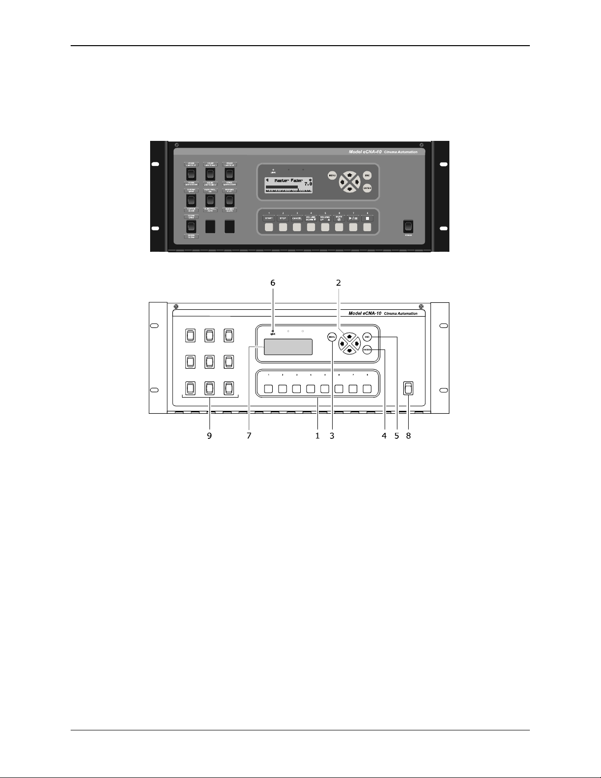
2. Control Panel
T e eCNA-10 is available in a 4RU steel cabinet. T e control panel features a display and navigation
keys, eig t user-definable keys and emergency manual override switc es.
Front Control Panel
1) User-Defined Keys T ese eig t (8) keys can be programmed to control any number of
functions.
2) C rsor Keys T e left, rig t, up and down cursor keys are used to navigate t e screens and
menu system.
3) MENU Key T is key is used to enter t e menu system.
4) ESC key T is key is used to abort a screen and return to t e previously viewed top level screen.
5) ENTER Key T is key is used to c ange or save a value.
6) LINK LED T is (Green) LED will lig t up w en t ere is a connection made to t e Et ernet port.
It will blink w en t ere is activity on t e port.
7) LCD Screen T e liquid crystal display screen s ows real time status and menus for viewing set
up data. T e screen is backlit for easy viewing in a dimly lit environment.
8) POWER Switch Used to turn on/off t e eCNA-10 controller.
9) Man al Override Switches T e control panel supports up to nine (9) manual control switc es
generally used for emergency manual override. T ese switc es circumvent t e electronic circuitry
giving t e operator t e ability to control major functions in t e event of a control system failure
or for testing purposes.
2eCNA-10 Operation and Installation Man al Version 1.270-00
© EPRAD Incorporated
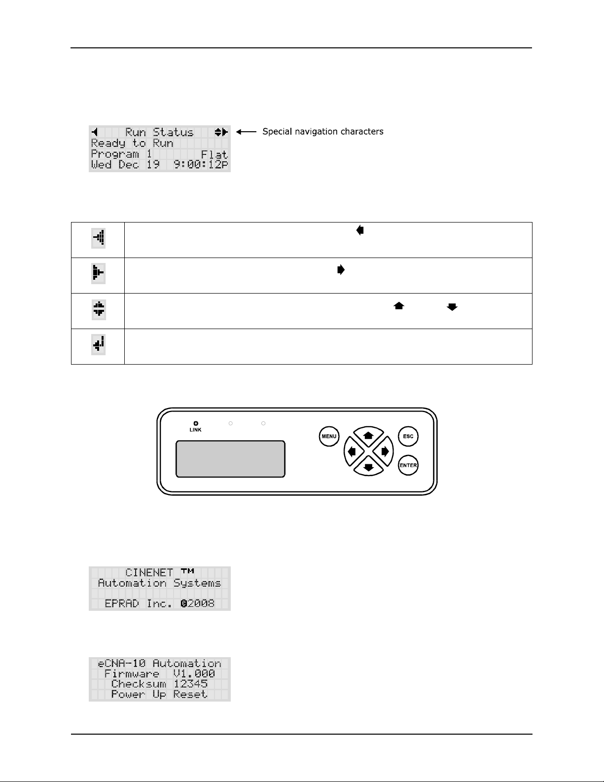
3. Display Screen
T e display screen is a four line by twenty c aracter liquid crystal display wit LED backlig ting . It
provides t e user wit information about t e system and a means by w ic t e operator can easily
manually control boot and auditorium equipment.
Special c aracters are displayed to aid in t e navigation of t e screens. T e c aracters are described
below.
Scroll Left / Back: Indicates t at pressing t e left cursor key will take you to
anot er screen at t e same or ig er level.
Scroll Rig t: Indicates t at pressing t e rig t cursor key will take you to
anot er screen at t e same level.
Scroll Up / Scroll Down: Indicates t at pressing cursor up or down keys will
scroll items in a list.
Enter: Indicates t at pressing t e ENTER key will select or c ange a value.
For example to select a menu item or c ange an output.
Display Navigation Keys
3.1 Power p Screen
On a normal power up, t e following screens will be displayed.
T e last line on t e second screen displays t e type of reset. Only ‘Power Up Reset’ and ‘Remote
Reset’ s ould be observed ere.
3
eCNA-10 Operation and Installation Man al Version 1.270-00
© EPRAD Incorporated
3.2 Top level screens
T e top level screens provide t e operator wit real-time information about boot and auditorium
functions suc as s ow status, auditorium sound and lig t levels, and screen format. Many functions
can be manually controlled from t ese screens. Press t e or keys to navigate to a new top level
screen. T ese screens are memorized by t e system, so t at on a power up, t e screen t at was
being viewed prior to a power down is displayed.
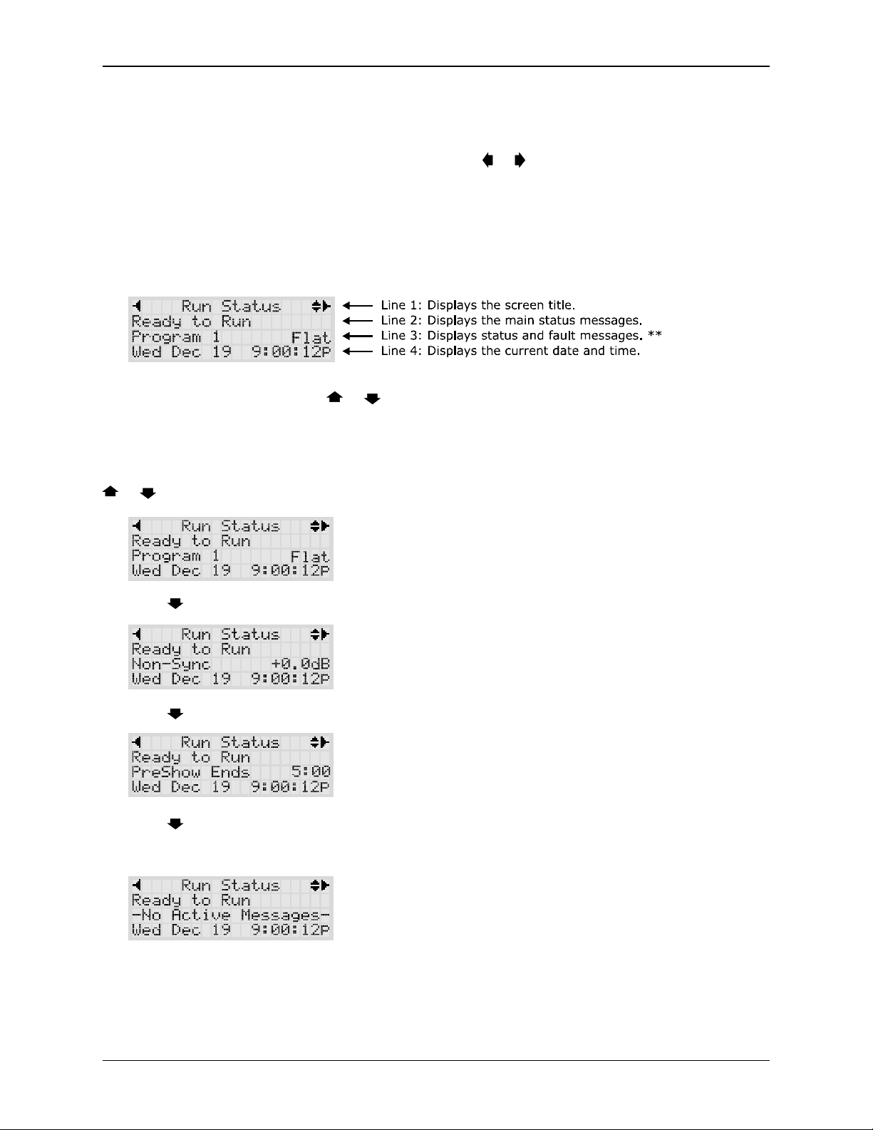
3.2.1 R n Stat s screen
T e R n Stat s screen displays
** Line 3 can be scrolled wit t e or keys.
Line 2 displays t e main status messages.
Line 3 displays t e active program and t e screen format. T e program number can be c anged from
t is screen. Press t e ENTER key for two seconds. T e program number will start to blink. Press t e
or keys to c ange t e number. Press t e ENTER key again.
Press t e key to display t e sound format and output level.
Press t e key to display t e active S ow Segment. T e Wait Time is also displayed ere.
Press t e key to display t e type of fault message. If no system faults are present, t e message
-No Active Messages- is displayed. See section 3.3.6 for list of system fault and status messages
and t eir definitions.
4eCNA-10 Operation and Installation Man al Version 1.270-00

© EPRAD Incorporated
3.2.2 O tp t Screen
T e Output screen is used to view t e status of various boot and auditorium equipment t at is
controlled by t e eCNA-10. If t e front panel ‘Manual Override’ option is enabled, t e operator can
also manually control t e outputs and functions from t is screen.
Press t e or keys to scroll t e display and view t e functions of interest. If manual override is
desired, scroll until t e function you want to control is on line 2. Press t e ENTER key.
3.3 Men Screens
T e menu screens provide configuration and status information about t e system and ot er
perip eral equipment.
Press t e MENU key on t e control panel.
Press t e or keys to scroll t e menu items. Press ENTER to select a menu item.
3.3.1 Network Stat s
T e Network Stat s screens display information about t e eCNA-10's communications networks
and t e equipment t at is connected to it.
Press ENTER from t e main menu screen to select Network Stat s.
Press ENTER to select Ethernet. T e Et ernet menu consists of all TCP/IP port connections
supported by t e eCNA-10. T e eCNA-10 supports t e following connections:
CineNet Host T e Windows CineNet Driver and CineSuite Program.
CAI 1 Cinema Automation Interface 1 for digital cinema clients (SMS, Content Server, etc.).
CAI 2 Cinema Automation Interface 2 for digital cinema clients (SMS, Content Server, etc.).
Http Server Web client and browser interface.
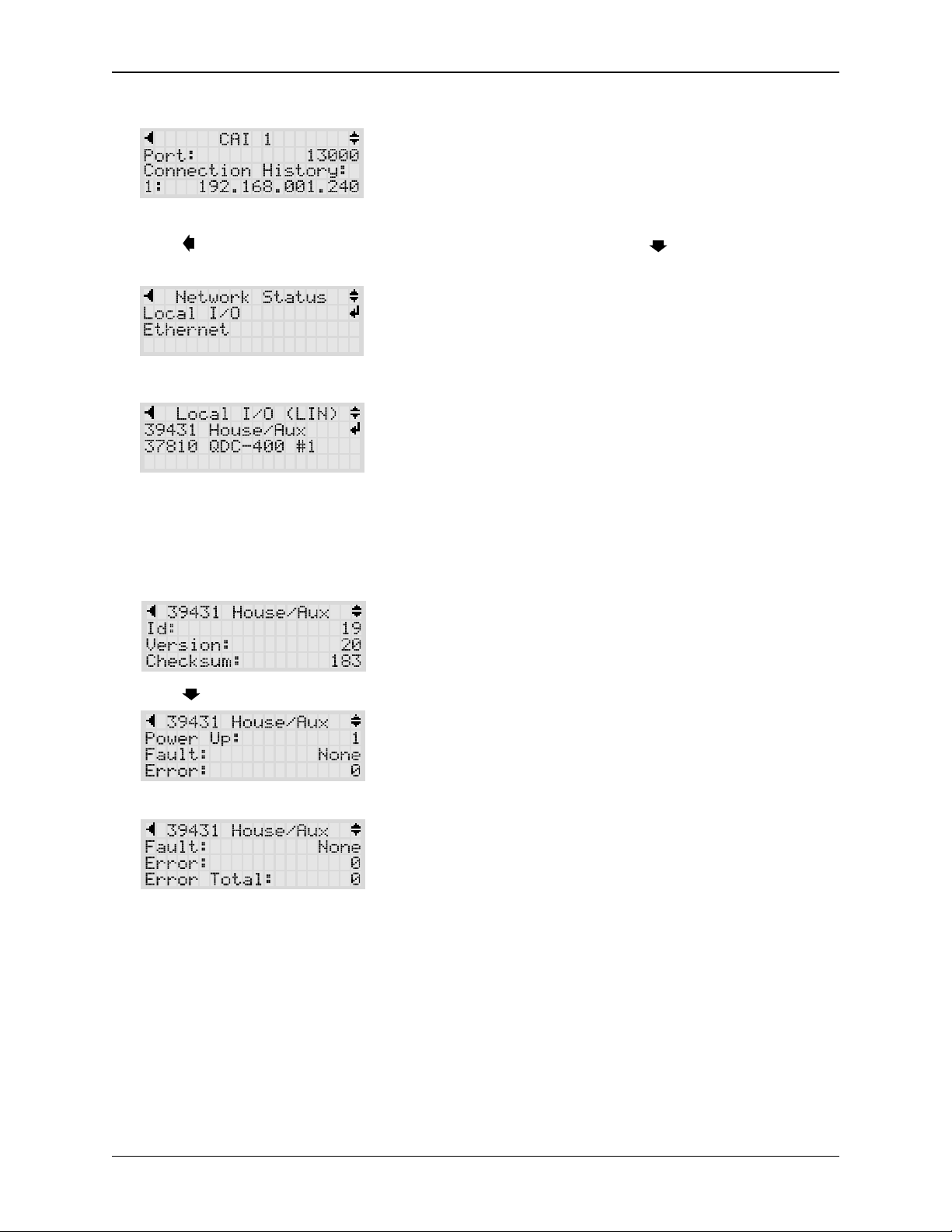
Scroll to CAI 1 wit t e or keys.
Press ENTER to select CAI 1. T is screen displays t e CAI 1 TCP port number and a istory of up to
5 connections since t e last power up. T e IP address of t e device is displayed on line 4. Press t e
or keys to scroll t e connection istory on line 4. T e ot er Et ernet status screens are similar
5
eCNA-10 Operation and Installation Man al Version 1.270-00
© EPRAD Incorporated
to t is one.
Press t e key twice to get back to t e Network Status screen. Press t e key and press ENTER
to view t e Local I/O status screen menu.
T e Local I/O (LIN) menu is dynamic and only t e devices connected will s ow up as a menu item.
Note: T e Local I/O Network is a proprietary network t at only supports eCNA application specific
devices.
Press ENTER to view t e 39431 House/Aux termination board. T is screen displays information
about t e board and real-time communication status.
Press t e key to view more items
6eCNA-10 Operation and Installation Man al Version 1.270-00

© EPRAD Incorporated
Id Screen Id (address) of t e device.
Version Firmware version
Checks m Firmware c ecksum value
Power Up Indicates t e number of times t e network device as reset, eit er due to a power up or
ot er, since t e eCNA-10 as been powered on.
Fa lt DevErr - T is message indicates t at t e eCNA-10 does not recognize t e network device.
T is could be due to software version incompatibility.
CommErr - Indicates t e network device is not responding.
TimeOut - Indicates a communication time out condition. T e network device as not
responded for more t an 5 seconds.
Error Indicates t e number of times t e eCNA-10 as polled t e device wit no response.
Error Total Indicates t e total number of times t e eCNA-10 as polled t e device wit no response since
t e eCNA-10 as been powered on.
3.3.2 Ethernet TCP/IP Screens
T e Et ernet TCP/IP screens display information about t e IP settings. Press ENTER from t e Menu
screen to select Ethernet TCP/IP. Press t e or keys to scroll t e settings. T ese settings can
only be viewed from t e local display. Use t e Web interface to modify any of t ese settings.
D plex Et ernet communications can operate in Half or Full Duplex mode. T is setting will depend
on t e device t at is connected to t e eCNA-10 (network switc , PC, etc.).
IP Address T is is t e IP address assigned to t e unit.
S bnet Mask T is is t e Subnet Mask assigned to t e unit.
Gateway IP Address T is is t e Gateway IP address assigned to t e unit.
Press t e key to go back to t e Main Menu.
7
eCNA-10 Operation and Installation Man al Version 1.270-00

© EPRAD Incorporated
3.3.3 User-Defined Keys Screen
T e User-Defined Keys screen displays t e configuration of t e eig t front panels keys. Press ENTER
on t e User-Defined Keys item. T ese settings can only be viewed from t e local display. Use t e
Web interface to modify t ese settings.
Press t e or keys to scroll t e key definitions.
Press t e key to go back to t e Main Menu.
3.3.4 Dimmer Screens
T e Dimmer screens display t e configuration of t e four c annel QDC-400 Dimmer Control boards.
Press ENTER on t e Dimmer menu item. T ese settings can only be viewed from t e local display.
Use t e Web interface to modify t ese settings.
Press t e or keys to scroll t e screen. Press ENTER to select t e card.
Press t e or keys to scroll t roug t e Up, Down, Mid 1 and Mid2 settings of all four c annels.
Press t e key to go back to t e Card menu. Press t e key again to go back to t e Main Menu.
8eCNA-10 Operation and Installation Man al Version 1.270-00

© EPRAD Incorporated
3.3.5 Information Screen
T e Information screen displays basic information about t e eCNA-10. Press ENTER on t e
Information menu item.
T is screens displays t e Model, Firmware version and firmware C ecksum.
Press t e key to go back to t e Main Menu.
3.3.6 Stat s and Fa lt Messages
T e t ird line of t e R n Stat s screen can display status and fault messages. Press t e or
key to scroll to t e status line. If t ere are no messages to display, t e message -No Active
Messages- is displayed.
Memory Fa lts
User configuration data is stored in battery-back memory. A c ecksum is calculated on a block of
data eac time new data is saved. T e c ecksum is re-calculated on a power up and compared to t e
previous saved c ecksum. If t ere is a mis-matc , a fault is generated. Any of t e following memory
faults indicate t at configuration data as c anged. Any memory fault will prevent a program from
being started. T e fault must be cleared before starting a program. Alt oug a Cancel will clear t e
fault and allow a program start, t is does not fix t e c ecksum mis-matc . So t e next power cycle
will generate a new memory fault. T e only way to fix t is is to force a new c ecksum calculation by
saving new data. T e best way to do t is is to restore data from your backup.
MEM FAULT:SYSTEM T is indicates a System Parameters Memory Fault.
MEM FAULT:PROG d-dd T is indicates a Program Memory Fault w ere d-dd is t e program and
step number of t e first occurrence of corrupt user data.
MEM FAULT:MACR d-dd T is indicates a Macro Memory Fault w ere d-dd is t e macro and step
number of t e first occurrence of corrupt user data.
LOW BATTERY FAULT T e Low Battery Fault indicates t at t e battery fell below t e t res old
voltage during a power down condition. T is message would usually be accompanied by one or more
memory faults.
CHECK RTC SETTINGS T is message is displayed if t e ardware clock and t e software clock
differ by more t an 60 seconds. T is normally won’t appen because t e software clock is set by
reading t e ardware clock on a power up. T ereafter, t e ardware clock is set w en t e NTP time
is received.
NTP SERVER NOT FOUND T is message is displayed if t e eCNA is configured to be an NTP client,
t e NTP IP address is not 0.0.0.0 and t e NTP server is not responding. T e message is activated if
t ere are t ree consecutive NTP server timeouts.
LIN: NETWORK FAULT T is message is displayed to indicate a loss of communications wit a Local
I/O Network (LIN) device. T is fault will cause a program s utdown or prevent a program from
starting. T is is a latc ed fault and a Cancel input is required to clear t e fault.
9
eCNA-10 Operation and Installation Man al Version 1.270-00

© EPRAD Incorporated
FIRE ALARM STOP T is message indicates a fire stop input, w ic would normally come from t e
fire alarm system. By default, t is is a latc ed fault and a Cancel input is required to clear t e fault.
LIN REMOTE STOP T is is a status message only. T is message indicates t at a stop input from a
Local I/O Network (LIN) device is activated. T is message as a t ree second re-triggerable one-
s ot.
LIN REMOTE START T is is a status message only. T is message indicates t at a start input from a
Local I/O Network (LIN) device is activated. T is message as a t ree second re-triggerable one-
s ot.
LIN REMOTE CANCEL INPUT T is is a status message only. T is message indicates t at a cancel
input from a Local I/O Network (LIN) device is activated. T is message as a t ree second re-
triggerable one-s ot.
CAI d REMOTE STOP T is is a status message only w ere d is 1, 2 or 3. T is message indicates
t at a stop input was received from a Cinema Automation Interface (CAI) c annel. T is message as
a t ree second re-triggerable one-s ot.
CAI d REMOTE START T is is a status message only w ere d is 1, 2 or 3. T is message indicates
t at a start input was received from a Cinema Automation Interface (CAI) c annel. T is message as
a t ree second re-triggerable one-s ot.
DIGITAL d FAULT T is message is displayed to indicate t at a digital input fault was activated
w ere d is 1 or 2. T is fault will cause a program s utdown or prevent a program from starting. T is
fault can be configured to be a latc ed fault requiring a Cancel to clear t e fault. See ‘Digital Fault
Input Latc ed’ on t e Setup: System Parameters screen.
CAI d FAULT T is message is displayed to indicate t at a digital input fault was activated w ere d
is 1, 2 or 3. T is fault will cause a program s utdown or prevent a program from starting.
IP ADDRESS CONFLICT T is message indicates t at more t an one eCNA-10 is configured wit t e
same IP Address.
SCREEN ID CONFLICT T is message indicates t at more t e one eCNA-10 is configured wit t e
same Screen Id. See Configuration DIP Switc es on t e Main CPU Board.
PROGRAM ABORT INPUT T is is a status message only. T is message indicates t at an abort was
activated. T is message as a t ree second re-triggerable one-s ot.
MACRO LIMIT: dd-dd T is is a runtime error message t at indicates t e macro call level limit was
reac ed. It indicates a Macro programming error. dd-dd is t e macro and step number t at made t e
call t at attempted to exceed t e call level limit. Use t e “Cancel” key or t e “Cancel” input to clear
t is message. Correct t e programming error.
REM ALRM ID: dd T is status message indicates t at anot er eCNA is sounding it’s alarm due to a
fault condition. dd is t e screen id of t e remote eCNA t at is faulted.
ALARM ON: PROG dd-dd T is status message indicates t at t e Alarm instruction was executed
by a program and t e local alarm is on. dd is t e program and step number.
ALARM ON: MACR dd-dd T is status message indicates t at t e Alarm instruction was executed
by a macro and t e local alarm is on. dd is t e macro and step number.
CMD LIMIT EXCEEDED T is error message indicates an “instruction” command was dropped from
t e command buffer (w ere delayed instructions are buffered). T e buffer is currently sized large
enoug t at t e user s ould never see t is message.
10 eCNA-10 Operation and Installation Man al Version 1.270-00

© EPRAD Incorporated
4. Config ring the Unit
T e eCNA-10 must be configured to operate on a network wit various network devices and wit t e
boot and auditorium equipment.
4.1 Config ring the Main CPU Board
T e Main CPU board (P/N 39425-1) incorporates several serial communication ports including an
Et ernet port. Eac of t ese ports ave specific purposes. T ere are 3 banks of DIP switc es used for
basic system configuration. T e LEDs provide an indication of power supply and serial
communications status.
1) Ethernet J2 a 10Base-T Et ernet RJ-45 connector.
2) RS-232 P8 is an RS-232 port used to set up t e Et ernet parameters. T e same parameters can
be set up from t e web browser interface.
3) RS-232 P9 is an RS-232 port used for CAI c annel 1 communications.
4) RS-485 P2 and P10 are t e LIN (Local I/O Network) connections. Serial data and power support
t e termination boards, dimmer control and any ot er LIN devices.
5) RS-485 P3 and P11 are connectors for t e isolated RS-485 LSN port.
6) Serial Port P14 supports t e CAI c annel 3. It requires t e optional 39446 RS-232 adapter
board.
7) Config ration DIP Switches S1 t roug S3 are used for eCNA configuration.
8) Stat s LEDs LED1 displays t e status of t e LSN and LED2 displays t e status of t e LIN. A fast
blink indicates t at t e eCNA is communicating wit a network device. LED3 is t e +5 volt
computer voltage.
11
eCNA-10 Operation and Installation Man al Version 1.270-00

© EPRAD Incorporated
9) Alarm T e internal alarm is used to alert boot personnel t at a s ow as stopped due to an
equipment malfunction. T e alarm is configured from t e System Parameters screen.
Configuration DIP Switc es
S1 F nction ON OFF
S1-1 Boot Loader Force Boot Loader on Power Up Application on Power Up *
S1-2 Supervisory Defaults Force Factory Defaults on Power Up Do Not Overwrite *
S1-3 Screen Id 20H bit Value = 20H (32 Decimal) Value = 00H (0 Decimal) *
S1-4 Screen Id 10H bit Value = 10H (16 Decimal) Value = 00H (0 Decimal) *
S1-5 Screen Id 08H bit Value = 08H (8 Decimal) Value = 00H (0 Decimal) *
S1-6 Screen Id 04H bit Value = 04H (4 Decimal) Value = 00H (0 Decimal) *
S1-7 Screen Id 02H bit Value = 02H (2 Decimal) Value = 00H (0 Decimal) *
S1-8 Screen Id 01H bit Value = 01H (1 Decimal) * Value = 00H (0 Decimal)
S2 F nction ON OFF
S2-1 Manual Control Screen Enable * Disable
S2-2 Password Enable * Disable
S2-3 C eck Focus Delay Alarm Enable Disable *
S2-4 Fire Stop Enable Disable *
S2-5 Not Defined Not Defined Not Defined *
S2-6 Not Defined Not Defined Not Defined *
S2-7 Host Event Log Enable * Disable
S2-8 Cinema Automation Interface Enable * Disable
S3 F nction ON OFF
S3-1 Not Defined Not Defined Not Defined *
S3-2 Not Defined Not Defined Not Defined *
S3-3 Not Defined Not Defined Not Defined *
S3-4 Not Defined Not Defined Not Defined *
S3-5 Not Defined Not Defined Not Defined *
S3-6 C eck Focus Delay Alarm (Remote) Disable RCM / RSM Alarm on Start * Enable RCM / RSM Alarm on Start
S3-7 Not Defined Not Defined Not Defined
S3-8 IP Defaults Force Defaults on Power Up Do Not Overwrite *
* Default
UNote: All DIP switc es are read by t e application once at power up. C anging t e
switc es w ile t e unit is powered on will not ave an effect until t e power is cycled.
12 eCNA-10 Operation and Installation Man al Version 1.270-00
Table of contents
Other EPRAD Home Theater System manuals


