Equus TT-WBC520 User manual
CONTACT
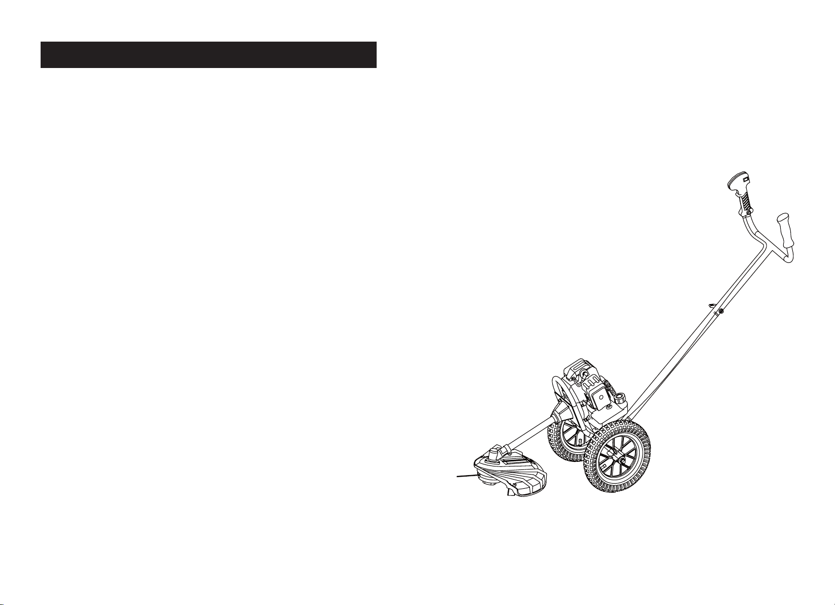
OPERATOR’S MANUAL
TT-WBC520 WHEELED
GRASS TRIMMER
IMPORTANT! IT IS ESSENTIAL THAT YOU READ THE INSTRUCTIONS IN THIS
MANUAL BEFORE ASSEMBLING, OPERATING AND MAINTAINING THIS MACHINE.

Sherpa Tools Ltd.
STWT52 WHEELED TRIMMER
If you experience any problems with this product,
please do not return to the store. Contact Sherpa
Tools direct on our UK helpline.
UK Helpline: 01522 283 020
www.sherpatools.co.uk June 2015
TROUBLESHOOTING
PROBLEM CAUSE CORRECTION
Will not start 1. Out of fuel 1. Fill fuel tank
2. Engine not choked properly 2. See TO START ENGINE instructions
(QJLQHÁRRGHG 3. Wait several minutes before trying again
'LUW\DLUÀOWHU &OHDQRUUHSODFHDLUÀOWHU
5. Water in fuel 'UDLQIXHOWDQNDQGFDUEXUHWWRUÀOOZLWKIUHVKIXHO
6. Clogged fuel tank/line 5HPRYHIXHOWDQNRUÀOWHUDQGFOHDQ
7. Loose spark plug wire 7. Make sure plug wire is seated properly on plug
8. Bad spark plug or improper gap 8. Replace spark plug or adjust gap
9. Carburettor out of adjustment 9. Make necessary adjustments
Hard to start 1. Throttle control not set properly 1. Place throttle control in FAST position
'LUW\DLUÀOWHU &OHDQRUUHSODFHDLUÀOWHU
3. Bad spark plug or improper gap 3. Replace spark plug or adjust gap
4. Stale or dirty fuel 'UDLQIXHOWDQNDQGFDUEXUHWWRUÀOOZLWKIUHVKIXHO
5. Loose spark plug wire 5. Make sure plug wire is seated properly on plug
6. Carburettor out of adjustment 6. Make necessary adjustments
Loss of power 1. Engine is overloaded &OHDQRUUHSODFHDLUÀOWHU
'LUW\DLUÀOWHU &OHDQRUUHSODFHDLUÀOWHU
3. Bad spark plug 3. Replace spark plug
6SHFLÀFDWLRQ77%&0RGHO1R77%&
Engine type: Single cylinder, air-forced cool, 2-stroke
Engine model: 1E44F-5
Displacement: 51.7cc
Rated output power: 1.4kw/7500rpm
Carburetor: Diaphragm type
Ignition: CDI
Fuel tank capacity: 1200ml
Handle Pipe diameter: 25mm
Working pipe diameter:26mm
8MM+9 Alloy transmission shaft
Cutting head: Nylon cutter
ENGINE SPECIFICATION

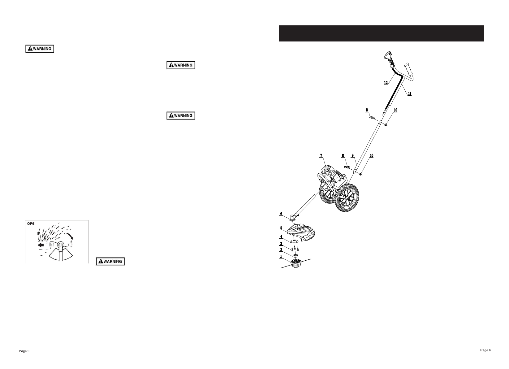
TRIMMER PARTS DIAGRAM
1. Trimmer Head
2. Head Spacer
3. Head Bolts
4. Protection Ring
5. Protection Guard
6. Geared Shaft
7. Engine & Chassis
8. Winged Screw
9. Nut
10. Lower Handle
11. Upper Handle
12. Throttle Cable
SAFETY FIRST
Instructions contained in warnings within this manual marked with a
symbol concern critical points which must be taken into consideration
to prevent possible serious bodily injury, and for this reason you are
requested to read all such instructions carefully and follow them without
fail.
WARNINGS IN THE MANUAL
WARNING
This mark indicates instructions which must be followed in order to
prevent accidents which could lead to serious bodily injury or death.
IMPORTANT
This mark indicates instructions which must be followed, or it leads to
mechanical failure, breakdown, or damage.
NOTE
This mark indicates hints or directions useful in the use of the product.
SAFETY INFORMATION
Warning Labels
Symbols on the machine
(1) Read owner’s manual before operating
machine.
(2) Wear head, eye and ear protection.
(3) Wear foot protection.
(4) Wear gloves.
(5) Beware of thrown objects.
(6) Warning / Attention
(7) Keep all children, bystanders and helpers 15
metres away from the brush cutter
For safe operation and maintenance,
symbols are carved in relief on the
machine. Please pay attention to all
instructions, symbols and labels to
ensure safe use.
(a) The port to refuel the “MIXED
PETROL”
Position: FUEL TANK CAP
(b) The direction A to close the choke
The direction B to open the choke
Position: AIR CLEANER COVER
J;OPZ\UP[PZÄ[[LK^P[OVUS`ÅL_PISL
line cutter. Never use cutting blade
made of metal or plastic. Position:
DEBRIS GUARD
(5)(2) (3) (4)(1) (6) (7)

1. Read this manual carefully
until you completely understand
and follow all safety and
operating instructions.
2. Keep this manual handy
so that you may refer to it
later whenever any questions
arise. Also note, if you have
any questions which cannot
be answered herein, contact
Sherpa Tools.
3. Always be sure to include
this manual when selling,
lending, or otherwise
transferring the ownership of
this product.
4. Never allow children
or anyone unable to fully
understand the directions
given in the manual to use the
machine.
WORKING CONDITION
1. When using the product, you
should wear proper clothing
and protective equipment:
(1) Helmet
(2) Ear protectors
(3) Protection goggles or face
protector
(4) Thick work gloves
(5) Non-slip-sole work boots
2. And you should carry with
you:
$WWDFKHGWRROVDQGÀOHV
(2) Properly stored fuel
(3) Spare trimmer line
(4) Things to notify your
working area (rope, warning
signs)
(5) Whistle (for collaboration or
emergency)
(6) Hatchet or saw (for removal
of obstacles)
3. Do not wear loose clothing,
jewellery, short trousers,
sandals, or go barefoot. Do not
wear anything which might be
caught by a moving part of the
unit. Secure hair so it is above
shoulder length.
WORKING CIRCUMSTANCE
1. Never start the engine inside
a closed room or building.
Exhaust gases contain
dangerous carbon monoxide.
2. Never use the product,
a. when the ground is slippery
RUZKHQ\RXFDQ·WPDLQWDLQD
steady posture.
b. At night, at times of heavy
fog, or at any other times when
\RXUÀHOGRIYLVLRQPLJKWEH
OLPLWHGDQGLWZRXOGEHGLIÀFXOW
to gain a clear view of the
working area.
c. During rain storms, during
lightning storms, at times of
strong or gale-force winds, or at
any other times when weather
conditions might make it unsafe
to use the product.
WORKING PLAN
1. You should never use
the product when under the
LQÁXHQFHRIDOFRKROZKHQ
suffering from exhaustion or
lack of sleep, when suffering
from drowsiness as a result
of having taken cold medicine
or at any other time when a
possibility exists that your
judgment might be impaired or
that you might not be able to
operate the product properly
and in a safe manner.
2. When planning your work
schedule, allow plenty of time
to rest. Limit the amount of
time over which the product
is to be used continuously to
somewhere around 30~40
minutes per session, and take
10~20 minutes of rest between
work sessions. Also try to
keep the total amount of work
performed in a single day under
2 hours or less.
,I\RXGRQ·WREVHUYHWKH
working time, or working
manner, Repetitive Stress
Injury (RSI) could occur. If you
feel discomfort, redness and
VZHOOLQJRI\RXUÀQJHUVRUDQ\
other part of your body, see a
doctor before getting worse.
2. To avoid noise complaints,
in general, operate product
between 8am and 5pm on
weekdays and 9am to 5pm
weekends.
Check and follow the local
regulations as to sound level
and hours of operations for the
product.
SAFE OPERATION
1
2
3
4
5
6
7
8
9
10
11
12
13
14
15
16
17
18
19
20
21
22
23
24
28
29
30
31
32
33
34
35
36
37
38
39
40
41
42
43
44
45
46
47
48
49
50
51
52
53
54
55
56
57
28
59
60
14
32
1
58
9
25
26
27
9
ENGINE PARTS DIAGRAM

Note that using any spark plugs
other than those designated
may result in the engine failing
to operate properly or in the
engine becoming overheated
and damaged.
7RLQVWDOOWKHVSDUNSOXJÀUVW
WXUQWKHSOXJXQWLOLWLVÀQJHU
tight, then tighten it a quarter
turn more with a socket wrench.
TIGHTENING TORQUE:
9.8~11.8 N.m
MUFFLER
Inspect periodically, the
PXIÁHUIRUORRVHIDVWHQHUV
any damage or corrosion. If
any sign of exhaust leakage
is found, do not use the brush
cutter and have it repaired
immediately.
Note that failing to do so may
result in the engine catching
RQÀUH
INTAKE AIR COOLING VENT
Never touch the cylinder,
PXIÁHURUVSDUNSOXJVZLWK
your bare hands immediately
after stopping the engine. The
engine can become very hot
when in operation, and doing
so could result in severe burns.
When checking the trimmer to
make sure that it is okay before
using it, check the area around
WKHPXIÁHUDQGUHPRYHDQ\
wood chips or leaves which
have attached themselves
to the brush cutter. Note that
failing to do so could cause the
PXIÁHUWREHFRPHRYHUKHDWHG
and that this in turn could cause
the brush cutter to catch on
ÀUH$OZD\VPDNHVXUHWKDW
WKHPXIÁHULVFOHDQDQGIUHHRI
wood chips, leaves, and other
waste before use.
• Check the intake air cooling
vent and the area around the
F\OLQGHUFRROLQJÀQVDIWHUHYHU\
25 hours of use for blockage,
and remove any waste which
has attached itself to the brush
cutter. Note that it is necessary
to remove the plug guard
shown in Figure in order to be
able to view the upper part of
the cylinder.
If waste gets stuck and causes
blockage around the intake air
cooling vent or between the
F\OLQGHUÀQVLWPD\FDXVHWKH
engine to overheat, and that
in turn may cause mechanical
failure on the part of the brush
cutter. (MA6)
&\OLQGHUÀQ
(2) Intake air cooling vent
(back)
PROCEDURES TO BE
PERFORMED AFTER EVERY
10 HOURS OF USE
5HPRYHWKHPXIÁHULQVHUWD
screwdriver into the vent, and
wipe away any carbon build up.
Wipe away any carbon buildup
RQWKHPXIÁHUH[KDXVWYHQWDW
the same time.
2. Tighten all screws, bolts, and
ÀWWLQJV
3. Check to see if any oil or
grease has worked its way in
between the clutch lining and
drum, and if it has wiped it
away using oil-free, lead-free
gasoline.
BEFORE STARTING THE
ENGINE
1. The area within a perimeter
of 50 feet (15m) of the person
using the product should be
considered a hazardous area
into which no one should enter.
If necessary, yellow warning
rope, warning signs should be
placed around the perimeter
of the area. When work is to
be performed simultaneously
by two or more persons,
care should also be taken
to constantly look around
or otherwise check for the
presence and locations of
other people working so as to
maintain a distance between
HDFKSHUVRQVXIÀFLHQWWR
ensure safety.
2. Check the condition of
working area to avoid any
accident by hitting hidden
obstacles such as stumps,
stones, cans, or broken grass.
Remove any obstacle before
beginning work.
3. Inspect the entire unit
for loose fasteners and fuel
leakage. Make sure that the
cutting attachment is properly
installed and securely fastened.
4. Be sure the debris guard is
ÀUPO\DWWDFKHGLQSODFH
STARTING THE ENGINE
1. Keep bystanders and
animals at least 50feet (15m)
away from the operating
point. If you are approached,
immediately stop the engine.
2. The product is equipped with
a centrifugal clutch mechanism,
so the cutting attachment
begins to rotate as soon as the
engine is started by putting the
throttle into the start position.
When starting the engine, place
the product onto the ground
LQDÁDWFOHDUDUHDDQGKROGLW
ÀUPO\LQSODFHVRDVWRHQVXUH
that neither the cutting part nor
the throttle come into contact
with any obstacle when the
engine starts.
Never place the throttle into
the high speed position when
starting the engine.
3. After starting the engine,
check to make sure that the
cutting attachment stops
rotating when the throttle is
moved fully back to its original
position. If it continues to rotate
even after the throttle has been
moved fully back, turn off the
engine and take the unit to your
authoriwed servicing dealer for
repair.
USING THE PRODUCT
Cut only materials
recommended by the
manufacturer. And use only for
tasks this machine is intended
for.
*ULSWKHKDQGOHVÀUPO\ZLWK
both hands using your whole
hand. Place your feet slightly
apart (slightly further apart than
the width of your shoulders) so
that your weight is distributed
evenly across both legs, and
always be sure to maintain
a steady, even posture while
working.
2. Keep cutting attachment
below waist level.
3. Maintain the speed of the
engine at the level required to
perform cutting work, and never
raise the speed of the engine
above the level necessary.
4. If the unit start to shake or
vibrate, turn off the engine and
check the whole unit. Do not
use it until the trouble has been
properly corrected.
5. Keep all parts of your body
away from rotating cutting
attachment and hot surfaces.
1HYHUWRXFKWKHPXIÁHU
spark plug, or other metallic
parts of the engine while
the engine is in operation or
immediately after shutting
down the engine. Doing so
could result in serious burns or
electrical shock.
IF SOMEONE COMES
1. Guard against hazardous
situations at all times. Warn
adults to keep pets and children
away from the area. Be careful
if you are approached. Injury
PD\UHVXOWIURPÁ\LQJGHEULV
2. If someone calls out or
otherwise interrupts you while
working, always be sure to turn
off the engine before turning
around.
MAINTENANCE
1. In order to maintain your
product in proper working order,
perform the maintenance and
checking operations described
in the manual at regular
intervals.
2. Always be sure to turn off
the engine before performing
any maintenance or checking
procedures.
The metallic parts reach high
temperatures immediately after
stopping the engine.
3. Under no circumstances
should you ever take apart the
product or alter it in any way.
Doing so might result in the
product becoming damaged
during operation or the product
becoming unable to operate
properly.
HANDLING FUEL
1. The engine of the product
is designed to run on a mixed
fuel which contains highly
ÁDPPDEOHSHWURO1HYHUVWRUH
FDQVRIIXHORUUHÀOOWKHWDQN
of the unit in any place where
there is a boiler, stove, wood
ÀUHHOHFWULFDOVSDUNVZHOGLQJ
sparks, or any other source of
KHDWRUÀUHZKLFKPLJKWLJQLWH
the fuel.
2. Never smoke while operating
WKHXQLWRUUHÀOOLQJLWVIXHOWDQN
:KHQUHÀOOLQJWKHWDQN
always turn off the engine and
allow it to cool down. Take a
careful look around to make
sure that there are no sparks or
RSHQÁDPHVDQ\ZKHUHQHDUE\
before refuelling.
4. Wipe spilled fuel completely
using a dry rag if any fuel
spillage occurs during
refuelling.
5. After refuelling, screw the
fuel cap back tightly onto the
fuel tank and then carry the
unit to a spot 10feet (3m) or
more away from where it was
refuelled before turning on the
engine.
TRANSPORTATION
1. When hand-carrying the
product, cover over the cutting
part if necessary, lift up the
product and carry it paying
attention to the blade.
2. Never transport the product
over rough roads over long
distances by vehicle without
removing all fuel from the fuel
tank. If doing so, fuel might leak
from the tank during transport.
Maintenance, replacement, or
repair of the emission control
device and systems may be
performed by any non-road
engine repair establishment or
individual.
• Always be sure to stop the
engine before inspecting the
brush cutter for problems or
performing maintenance.
• Never alter the brush cutter or
take the engine apart.
• Things to check before using
brush cutter.
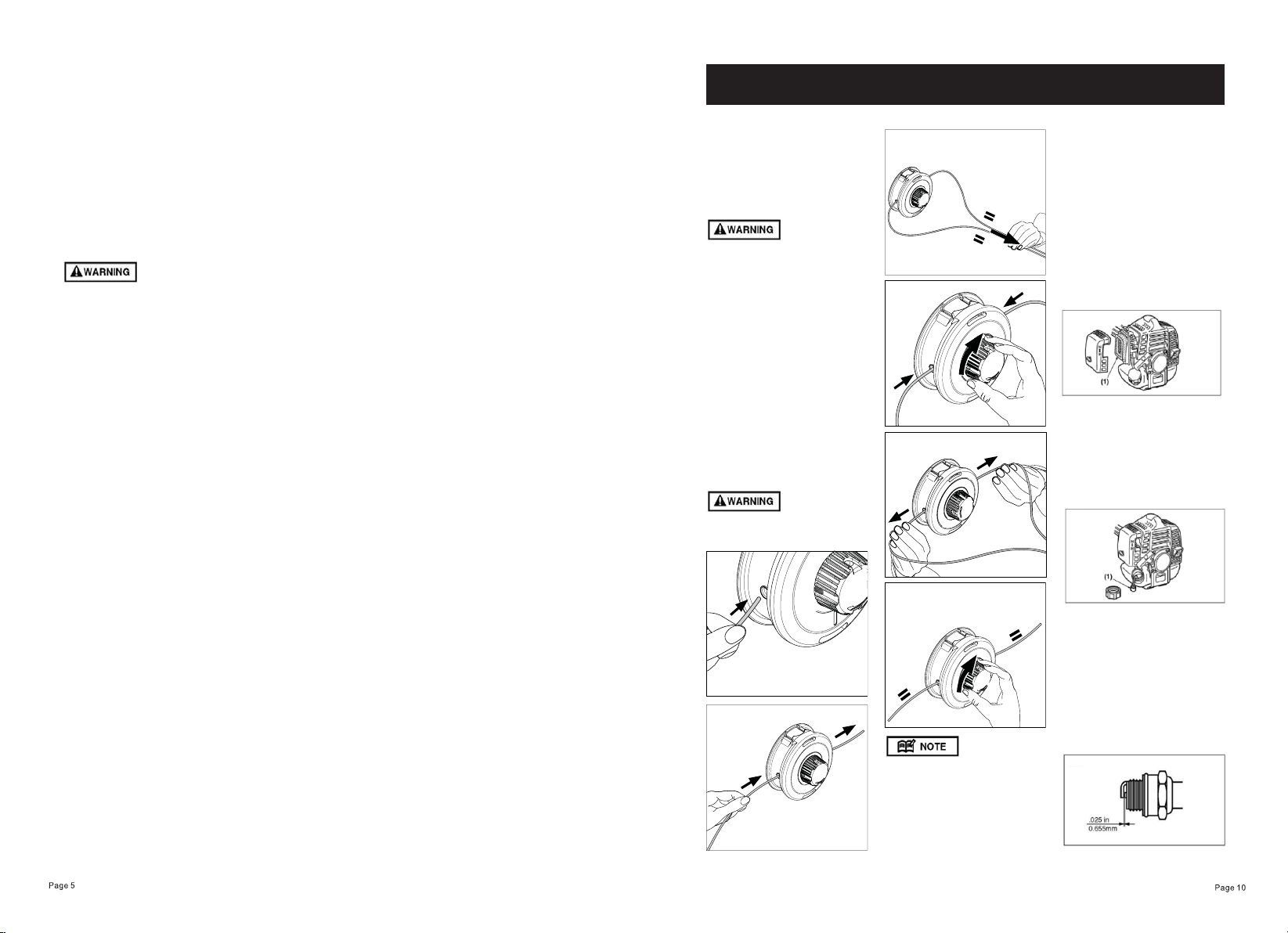
REFILLING TRIMMING LINE
For replacement line, use a
diameter of 3.0mm. The spool
is capable for a line up to 4m
on the head. Avoid using a
larger line as it may cut down
the trimming performance.
For safety reasons, do not use
metal reinforced line.
We recommend using Oregon
Duoline 3.00mm (part no.
106502E)
AIR FILTER
7KHDLUÀOWHULIFORJJHG
will reduce the engine
performance. Monthly check
DQGFOHDQWKHÀOWHUHOHPHQW
in warm, soapy water as
required. Dry completely before
installing. If the element is
broken or shrunk, replace with
a new one.
$LUÀOWHU
FUEL FILTER
When the engine
runs short of fuel supply, check
WKHIXHOFDSDQGWKHIXHOÀOWHU
for blockage.
)XHOÀOWHU
SPARK PLUG
6WDUWLQJIDLOXUHDQGPLVÀULQJ
are often caused by a fouled
spark plug. Periodically clean
the spark plug and check that
the spark gap is in the correct
range.
When you take off the spark
plug, twist and pull off the cap.
MAINTENANCE
LINE HEAD USAGE
1. Always wear eye protection
such as safety goggles. Never
lean over the rotating cutting
head. Rocks or other debris
could be thrown into eyes
and face and cause serious
personal injury.
2. Keep the debris guard
attached in place at all times
when the unit is operated.
TRIMMING GRASS AND
WEEDS
•Always remember that the TIP
of the line does cutting. You
will achieve better results by
not crowding the line into the
cutting area. Allow the unit to
trim at its own pace.
1. Hold the unit so the head
is off the ground and is tilted
about 20 degrees toward the
sweep direction. (OP6)
2. You can avoid thrown debris
by sweeping from your right to
the left.
3. Use a slow, deliberate action
to cut heavy growth. The rate
of cutting motion will depend on
the material being cut. Heavy
growth will require slower
action than will light growth.
4. Never swing the unit so hard
as you are in danger of losing
your balance or control of the
unit.
5. Try to control the cutting
motion with the hip rather than
placing the full workload on the
arm and hands.
6. Take precautions to avoid
wire, grass and dead, dry, long-
stem weeds from wrapping
around the head shaft. Such
materials can stall the head
and cause the clutch to slip,
resulting in damage to the
clutch system if repeated
frequently.
ADJUSTING THE LINE
LENGTH
• Your brush cutters is equipped
with a bump feed type nylon
line head that allows the
operator to advance the line
without stopping the engine.
When the line becomes short,
lightly tap the head on the
ground while running the
engine at full throttle.
• Each time the head is
bumped, the line advance
about 1 inch(25.4 mm). For
better effect, tap the head on
bear ground or hard soil. Avoid
bumping in thick, tall grass
as the engine may stall by
overload.
• The rotating parts fastened
incorrectly may cause serious
accident to the operator.
• Make sure that the head is not
bent, warped, cracked, broken
or damaged.
,I\RXÀQGDQ\HUURUWRWKH
head, discard it and change
new one.
• By using the harness, hang
the unit on your right side.
Adjust the harness length
so that the cutting head may
become parallel to the ground.
• Make sure to use harness and
cutting attachment guard. If not,
it is very dangerous when you
slip or lose your balance.
• If the grass or other object
gets caught in the head, or
if the unit starts to shake or
vibrate, turn off the engine and
check the head.
• Turn off the engine and make
sure the head has completely
stopped before checking the
blade, and removing any object
got caught in.
1. INSTALLING HANDLE
Insert the lower handle (9) into
the mounting cup at the bottom
of the drive unit (7). Align holes
and thread handle screw (8)
through the handle and tighten
nut (10). Insert upper handle
(11) into top of lower handle (9).
Align holes and thread handle
screw (8) through the handle
and tighten nut (10).
Remove side cover from engine
unit (7) using hex key. Pass
throttle wiring under engine and
fuel tank and then up in front
of engine. Insert throttle cable
into place and tighten screw
to secure. Push both pairs of
electric connectors together to
secure. Ensure the wires are
connected with the matching
colour wire from the engine.
2. INSTALLING SHAFT
Line shaft (6) up with entry
point at bottom of engine (7).
,QVHUWDQGSXVKÀUPO\LQWR
place. Ensure the bottom
end of the shaft is pointing
straight down in preparation of
attaching protection shield and
cutting head. Push the upper of
the two bolts through shaft and
tighten. Then tighten the lower
bolt to clamp around the shaft.
3. INSTALLING PROTECTION
SHIELD
Align the protection guard (5)
with the head of the shaft (6).
Attach the protection guard (5)
and ring (4) with the three bolts
supplied (3).
4. INSTALLING CUTTING
HEAD
Push spacer (2) onto shaft
underneath protection guard(5).
While locking the gear shaft
by inserting the hexagon bar
into the upper holder and the
housing, rotate the cutting
head to engage threads. Hand
tighten it securely.
4. INSTALLING TRIMMER
LINE
See diagram below.
ASSEMBLY

3HWUROLVYHU\ÁDPPDEOH
Avoid smoking or bringing any
ÁDPHRUVSDUNVQHDUIXHO
• Wipe up all spills before
starting the engine.
• Make sure to stop the
engine and allow it cool before
refuelling the unit.
.HHSRSHQÁDPHVDZD\IURP
the area where fuel is handled
or stored.
• Never use oil for 4 cycle
engine use or water cooled
2-cycle engine.
• Never use “FUEL WITH
NO OIL (NEAT UNLEADED
PETROL)”.
• Never use fuel laced with
water.
• Mixed fuels which have
been left unused for a period
of one month or more may
clog the carburetor or result in
the engine failing to operate
properly. Put remained fuel into
an air-tight container and keep
it in the dark and cool room.
• Please ask for “mixed
gasoline for air-cooled 2-cycle
engines” at your nearest gas
station, or use fuel made by
putting unleaded gasoline for
automobiles and air-cooled
2-cycle engine oil into a mixing
container in accordance with
the following ratios and then
shaking to mix well.
Mixing ratios:
When using commercially
available 2 stroke oil:
40:1
OIL
It is recommended that you use
a high quality 2 stroke oil in this
machine with an ethanol shield.
Sherpa recommends use of
B3C oil in the wheeled trimmer,
when using this product you
are able to mix petrol to oil at
a 50:1 ratio, as opposed to the
usual 40:1 with other 2 stroke
oils.
Ethanol Shield 2 Stroke Oil
reduces engine temperature
&&7SURWHFWVDJDLQVWVSHFLÀF
forms of corrosion, reduces
exhaust smoke output and
extends engine life. This oil will
stabilise fuel for up to a year.
100ml - B3C2ST1S
1l - B3C2STLRT
STORAGE
Aged fuel is one of major
causes of engine starting
failure. Before storing the unit,
empty the fuel tank and run
the engine until it uses all the
fuel left in the fuel line and the
carburetor. Store the unit indoor
taking necessary measures for
rust prevention.
FUEL
STARTING ENGINE
The cutting head will start
rotating upon the engine starts.
5HVWWKHXQLWRQDÁDWÀUP
place. Keep the cutting head
off the ground and clear of
surrounding objects as it will
start rotating upon starting of
the engine.
2. Ensure the choke lever to
the closed position (down).
(OP2)
(1) Choke lever
(2) Closed position
(3) Open position
3. Set the ignition switch to the
“start” position.
4. Push the primer bulb pump
ÀYHRUVL[WLPHV23
5. While pulling the throttle
trigger all the way in, push the
throttle lock button, and release
the throttle, then the throttle
lever is in the “Start position”.
(OP3)
(4) Ignition switch
(5) Throttle lock button
(6) Throttle trigger
6. Move the choke lever to the
open position (up) (OP2).
7. Pull out the starter rope
quickly to start engine. (OP4)
Avoid pulling the rope to its end
or returning it by releasing the
knob. Such actions can cause
starter failures.
8. Close choke by moving
leaver (1) to closed position
(down).
9. Run engine for a 10-20
seconds before releasing
throttle lock button by gently
pulling on throttle trigger and
releasing again.
10. Allow the engine to warm
up for several minutes before
starting operation.
1. When restarting the engine
immediately after stopping it,
leave the choke open (OP2)
and push the primer pump
several times (OP4).
2. Overchoking can make the
engine hard to start due to
excess fuel. If the engine failed
to start after several attempts,
open the choke and repeat
pulling the rope, or remove the
spark plug and dry it.
STOPPING ENGINE
1. Release the throttle lever
and run the engine for a half
minute.
2. Shift the ignition switch to the
STOP position.
Except for an emergency,
avoid stopping the engine while
pulling the throttle lever.
ADJUSTING IDLING SPEED
(OP5)
1. If the engine tends stop
frequently at idling mode, turn
the adjusting screw clockwise
a fraction.
2. When the cutting head keeps
rotating after releasing the
trigger, turn the adjusting screw
anticlockwise.
Warm up the engine before
adjusting the idling speed.
OPERATION
(6)
(5)
Table of contents
Popular Trimmer manuals by other brands

Ryobi
Ryobi RY34440 Replacement parts list

Bosch
Bosch Art 2300 Easytrim Accu instruction manual

Coopers of Stortford
Coopers of Stortford Victor Tools H224 Instructions for use

hecht
hecht 675 Instructions for use

Husqvarna
Husqvarna 325R X-SERIES Operator's manual

Shindaiwa
Shindaiwa DH254 Owner's/operator's manual


Black & Decker
Black & Decker 616081-00 instruction manual

RedMax
RedMax CHTZ2400 Owner's/operator's manual

Premier
Premier StakCut 724 instruction manual

Cosmopolitan
Cosmopolitan KLR928981478 instruction manual

Stihl
Stihl HSA 50.1 instruction manual

EINHELL
EINHELL RG-ET 7535 Original operating instructions