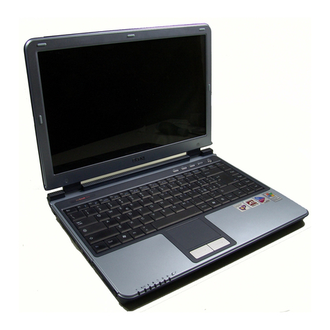
Ergo Mercury 3 User manual

User Manual
Ergo Mercury 3 Laptop
Ergo Computing UK Ltd.
Mere Way, Ruddington Fields, Ruddington, Nottingham, NG11 6JS
Tel: 0115 914 4144 Fax: 0115 914 4155
www.ergo.co.uk

2
Federal Communications Commission (FCC) Statement
This device complies with Part 15 of the FCC Rules. Operation is subject to the following two
conditions:
• This device may not cause harmful interference, and
• This device must accept any interference received; including interference that may cause
undesired operation.
This Equipment has been tested and found to comply with the limits for a Class B digital device,
pursuant to Part 15 of the FCC rules. These limits are designed to provide reasonable protection
against harmful interference in a residential installation. This equipment generates uses and can
radiate radio frequency energy and, if not installed and used in accordance with the instructions,
may cause harmful interference to radio communications. However, there is no guarantee that
interference will not occur in a particular installation. If this equipment does cause harmful
interference to radio or television reception, which can be determined by turning the equipment off
and on, the user is encouraged to try to correct the interference by one or more of the following
measures:
• Reorient or relocate the receiving antenna.
• Increase the separation between the equipment and receiver.
• Connect the equipment into an outlet on a circuit different from that to which the receiver is
connected.
• Consult the dealer or an experienced radio/TV technician for help.
CAUTION! Changes or modifications to this unit not expressly approved by the party
responsible for the compliance could void the user's authority to operate this equipment.
FCC RF Radiation Exposure Statement:
1. This Transmitter must not be co-located or operating in conjunction with any other antenna or
transmitter.
2. This equipment complies with FCC RF radiation exposure limits set forth for an uncontrolled
environment. This device was tested for typical lap held operations with the device contacted
directly to the human body to the back side of the notebook computer. To maintain compliance
with FCC RF exposure compliance requirements, avoid direct contact to the transmitting
antenna during transmitting.

3
CONTENTS
TAKING CARE OF YOUR NOTEBOOK PC...................................................5
1 BEFORE YOU START...............................................................................9
1-1 Making sure you have everything...................................................9
1-2 Finding where everything is located ............................................10
2 GETTING STARTED ...............................................................................19
2-1 Power Sources ...............................................................................19
2-2 Display Panel..................................................................................22
2-3 Starting Your Notebook PC ...........................................................24
2-4 Status Display Indicators ..............................................................26
2-5 Using the Keyboard .......................................................................29
2-6 Volume Control ..............................................................................31
2-7 Power Management........................................................................32
3 USING YOUR NOTEBOOK PC...............................................................35
3-1 Touchpad Pointing Device ............................................................35
3-2 Memory Card Reader .................................................................... 38
3-3 Optical Drive...................................................................................39
3-4 PC Cards.........................................................................................46
3-5 Memory Upgrade Module ..............................................................48
4 TROUBLESHOOTING ............................................................................53
4-1 Identifying the Problem .................................................................53
APPENDIX....................................................................................................54
Notebook Specifications .......................................................................54
WLAN Specifications .............................................................................55

4
This page is intentionally left blank.

5
TAKING CARE OF YOUR
NOTEBOOK PC
To prevent possible overheating of the
computer’s processor, make sure you don’t
block the openings provided for ventilation.
DO NOT place or drop objects on the com-
puter and DONOT apply heavy pressure on it. DO NOT subject the computer to magnetic
fields.
DO NOT place on uneven or unstable work
surfaces.
DO NOT press or touch the display panel.
DO NOT use your notebook computer under
harsh conditions.

6
DO NOT place near fire or other sources of
heat. DONOT tamper with the batteries. Keep them
away from children.
DO NOT expose to direct sunlight. DONOT use or store in extreme temperatures.
Avoid sudden changes in temperature or hu-
midity by keeping it away fromA/C and heat-
ing vents.
DONOTexpose the computer to rain or mois-
ture.

7
DO NOT expose to dust and/or corrosive
chemicals. DO NOT slam your notebook shut and never
pick up or hold your notebook by the display.
DONOTspray water or any other cleaning flu-
ids directly on the display. If you are traveling with your computer, re-
member to carry it as hand luggage. Do not
check it in as baggage.

8
This page is intentionally left blank.

9
1 BEFORE YOU START
1-1 Making sure you have everything
When you receive your notebook PC, unpack it carefully, and check to make sure
you have all the items listed below. For a pre-configured model you should have the
following:
• Notebook Computer
• Lithium ion battery
• AC adapter with AC power cord
• Driver and Applications CD
• Getting Started Guide or User Guide
Depending upon the configuration of your notebook, you may have also received
the following items:
• CD-ROM Application CD
• DVDApplication CD
• DVD / CD-RW Combo Application CD
Once you have checked and confirmed that your notebook system is complete,
read through the following pages to learn about all of your notebook components.

1. BEFORE YOU START
10
1-2 Finding where everything is located
1-2-1 OPENING THE DISPLAY PANEL
1. Slide the latch located at the top of the display panel to the right. This releases
the locking mechanism and raises the display slightly.
2. Lift the display backwards, being careful not to touch the screen, until it is at a
comfortable viewing angle.
Display
Panel
Latch

11
1. BEFORE YOU START
1-2-2 TOP COMPONENTS
The following is a brief description of your notebook’s top components.
Display Panel
The display panel is a color LCD panel with back lighting for the display of text
and graphics.
Suspend/Resume/Power On Button
This button turns your notebook pc on and off as well as put it to sleep. (See
Suspend/Resume/Power On Button in 2-3-1 Power On for more information.)
Keyboard
A full-size keyboard with dedicated Windows keys.
Suspend/Resume/
Power On Button
Scroll Buttons TouchPad
Pointing Device
Built-in
Speaker
Built-in
Speaker
Status Display
Indicators
Keyboard
Display Panel Instant Keys

1. BEFORE YOU START
12
Scroll Buttons
The scroll buttons allow you to scroll up and down documents. It acts similar to a
scroll wheel on a mouse.
Stereo Speakers
The built-in dual speakers allow for stereo sound.
Status Display Indicators
The Status display indicator lights correspond to specific components of your
notebook. (See suspend notebook activity without powering off, resume your
notebook from suspend mode, and power on your notebook when it has been shut
down from Windows. (See Suspend/Resume/Power On Button in 2-3-1 Power On
for more information.)
Touchpad Pointing Device
The Touchpad pointing device is a mouse-like cursor control with four buttons
(left, right, and two scroll buttons).
Instant Keys
The four instant keys allow you to launch your favorite email and internet appli-
cations with the touch of a button.

13
1. BEFORE YOU START
1-2-3 FRONT PANEL COMPONENTS
The following is a brief description of your notebook’s front panel components.
Built-in Stereo Speakers
The built-in dual speakers allow for stereo sound.
Status Display Indicators
The Status display indicator lights correspond to specific components of your
notebook. (See suspend notebook activity without powering off, resume your
notebook from suspend mode, and power on your notebook when it has been shut
down from Windows. (See Suspend/Resume/Power On Button in 2-3-1 Power On
for more information.)
Display Panel Latch
The display panel latch locks and releases the display panel.
Built-in
Speaker Built-in
Speaker
Display Panel Latch
Hard Disk Drive
Status Display
Indicators

1. BEFORE YOU START
14
1-2-4 LEFT-SIDE PANEL COMPONENTS
The following is a brief description of your notebook’s left-side components.
Kensington Lock Port
The Kensington lock slot allows you to secure your notebook to an immovable
object through an optional security cable.
Modem (RJ-11) Port
The modem (RJ-11) port is used to attach a telephone line to the internal 56K
modem.
LAN Port (RJ-45)
The LAN port is designed to support a 10/100/1000 Base-T standard RJ-45 plug.
Microphone Jack
The microphone jack allows you to connect an external mono microphone.
Headphone Jack
The headphone jack allows you to connect headphones or external speakers with
amplifer.
PC Card Slots
The PC Card Slots allow you to install two Type II or one Type III PC Card.
Microphone Jack
Headphone Jack
PC Card
Slots
PC Card
Eject Buttons
Ethernet
Port
(RJ-45)
Modem
Port
(RJ-11)
Kensington
Lock Slot Memory Card Reader

15
1. BEFORE YOU START
Memory Card Reader
The memory card reader offers the fastest and most convenient method to transfer
pictures, music and data between your notebook PC and flash-compatible devices
such as digital cameras, MP3 players, mobile phones, and PDAs.
1-2-5 RIGHT-SIDE PANEL COMPONENTS
The following is a brief description of your notebook’s right-side components.
Lithium ion Battery Bay
The internal battery pack can be removed for installation of a fully charged battery
pack. (See 2-1-3 Replacing the Battery for more information.)
Optical Drive
The Optical Drive allows you to play back a media disc.
Emergency Optical Drive Tray Release
The Emergency Optical Drive Tray Release allows you to open the Optical Drive
tray without powering on your notebook.
Optical Drive Eject Button
The Optical Drive Eject Button allows you to open the Optical Drive tray to
remove or install a DVD, CD-R, or CD-ROM.
Lithium ion
Battery Bay
Emergency
Optical Drive
Tray Release
Optical
Drive
Optical Drive
Eject Button

1. BEFORE YOU START
16
1-2-6 BACK PANEL COMPONENTS
The following is a brief description of your notebook’s back panel components.
Infrared Port
The fast IrDA-compatible port allows you to communicate wirelessly with another
IrDA-compatible infrared device without a cable.
Power Adapter Port
The power adapter port allows you to plug in the AC adapter to power your note-
book and charge the internal Lithium ion battery.
PS/2 Port
The PS/2 port allows you to connect an external PS/2 keyboard, mouse or numeric
keypad. (See 3-6-8 PS/2 Port for more information.)
IEEE 1394 Port
The 1394 port is used to connect between your and a peripheral such as a digital
video camera.
USB Ports (V2.0)
The two USB ports allow you to connect Universal Serial Bus devices.
Serial Port
The serial port allows you to connect serial (RS-232C) devices. (This is also some-
times referred to as a COM port.) (See 3-6-6 Serial Port for more information.)
External Monitor Port
The external monitor port allows you to connect an external monitor.
Parallel (Printer)
Port
External
Monitor
Port
USB
Ports
IEEE
1394
Port
Power
Adapter
Port
PS/2
Port
Serial
Port
Infrared
Port

17
1. BEFORE YOU START
Parallel (Printer) Port
The parallel port allows you to connect parallel devices, such as a printer. (This is also
sometimes referred to as an LPT port.)
1-2-7 BOTTOM COMPONENTS
The following is a brief description of your notebook’s bottom panel components.
Hard Disk Drive Bay
The internal hard disk drive is accessible through the hard disk drive bay.
Mini-PCI Card Bay
The mini-PCI card is accessible through the this bay.
Battery Bay Latch
The battery bay latch locks and releases the Lithium ion battery.
Memory Compartment
The memory compartment contains the system RAM.
Lithium ion
Battery Bay
Memory
Compartment
Hard
Disk
Drive
Bay
Battery
Bay
Latch
Mini-PCI
Card
Cover
Optical
Drive Bay

1. BEFORE YOU START
18
Lithium ion Battery Bay
The battery bay contains the internal Lithium ion battery. It can be opened for the
removal of the battery when stored over a long period of time or for swapping a
discharged battery with a charged Lithium ion battery.
Optical Drive Bay
The internal optical drive is accessible through the optical drive bay.

19
2 GETTING STARTED
2-1 Power Sources
Your notebookPChastwo possiblepowersources:a primary Lithiumionbattery oran
ACadapter.
2-1-1 CONNECTING THE POWER ADAPTERS
TheAC adapter provides powerforoperating yournotebook PC and chargingthe
batteries.
Connecting the AC Adapter
1. Plug theDC outputcableintothe adapterpower portof yournotebook PC.
2. Plug theACadapter intoanACelectrical outlet.
TheLithiumionbatteryisnotchargeduponpurchase.Initially,you
willneed to connecttheAC adapterto useyournotebook PC.
POINT

20
2. GETTING STARTED
2-1-2 RECHARGING THE BATTERY
TheLithiumionbatteryis rechargedinternallyusingtheACadapter.To rechargethe
battery makesure thebattery that needsto becharged is installedin yournotebook PC
and connecttheAC adapter.
Thereisno memoryeffectontheLithium ionbattery, thereforeyou donotneedto
dischargethebatterycompletelybeforerecharging.Thechargetimeswillbesignificantly
longerifyour notebookPCis inusewhile thebatteryischarging.Ifyouwantto charge
thebattery morequickly,putyournotebook PCintoSuspendmode, orturnitoffwhile
theadapter ischargingthebattery. (See2-7PowerManagementformoreinformation
onSuspend modeandshutdown procedure)
Low Battery State
Whenthebatteryisrunning low,alowbatterynotification messagewillappear.Ifyou
donotrespond tothelow batterymessage,thebattery willcontinuetodischarge untilit
istoo lowto operate.Whenthishappens,yournotebook PCwill gointo Suspend
mode.Thereis noguarantee thatyour datawillbesavedonce thenotebook reaches
thispoint.
To protectyour notebookPC fromdamage, useonlythepower
adapterthat came withthe notebook PCbecause eachpower
adapterhasitsown poweroutputrating.
Once yournotebook PCgoes intoDead Battery Suspend mode youwill beunable to
resumeoperationuntil youprovide asourceof powereitherfromanadapter, ora
charged battery. Onceyou haveprovided power, youwill needtopress theSuspend/
Resumebuttontoresumeoperation. IntheDead BatterySuspend mode,your datacan
bemaintained forsome time, butifapowersource isnotprovided promptly, thePower
indicatorwillstopflashingandgoout,meaning thatyouhavelostthe datathatwasnot
stored.Once youprovide power, youcan continueto useyournotebook PCwhile an
adapterischargingthebattery.
Shorted Battery
TheStatusIndicator panelusesa symbolinsidethebatteryoutline oftheBatteryLevel
indicatortodisplaytheoperating levelavailablein thatbattery.Ifthis displayshowsa
ShortedBattery, itmeansthatthebattery isdamagedand mustbe replacedsoit does
notdamageanyother parts ofyour notebookPC.
CAUTION
Table of contents
Other Ergo Laptop manuals
