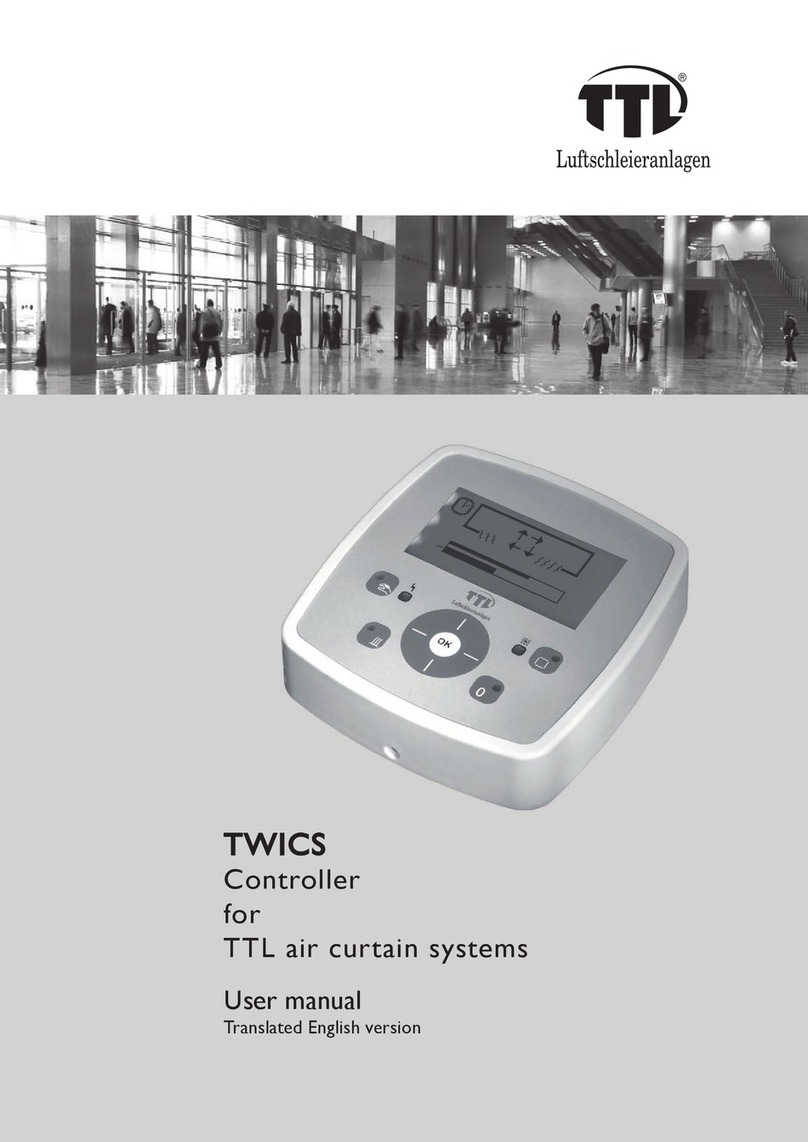
ESD electronic CAN-CBX-CPU5202 User manual

CAN-CBX-CPU5202
Smart Real-Time Controller
with Graphic Interface
Hardware Manual
to Product C.3072.02,
C.3072.03,
C.3072.04
CAN-CBX-CPU5202 Hardware Manual • oc. No.: C.3072.21 / Rev. 1.0 Page 1 of 40
esd electronic system design gmbh
Vahrenwalder Str. 207 • 30165 Hannover • ermany
http://www.esd.eu
Phone: +49 (0) 511 3 72 98-0 • Fax: +49 (0) 511 3 72 98-68

N T E
The information in this document has been carefully checked and is believed to be entirely reliable.
esd makes no warranty of any kind with regard to the material in this document, and assumes no
responsibility for any errors that may appear in this document. In particular descriptions and
technical data specified in this document may not be constituted to be guaranteed product features
in any legal sense.
esd reserves the right to make changes without notice to this, or any of its products, to improve
reliability, performance or design.
All rights to this documentation are reserved by esd. istribution to third parties, and reproduction
of this document in any form, whole or in part, are subject to esd's written approval.
© 2012 esd electronic system design gmbh, Hannover
esd electronic system design gmbh
Vahrenwalder Str. 207
30165 Hannover
Germany
Phone: +49-511-372 98-0
Fax: +49-511-372 98-68
E-Mail: [email protected]
Internet: www.esd.eu
Trademark Notices
CANopen® and CiA® are registered community trademarks of CAN in Automation e.V.
All other trademarks, product names, company names or company logos used in this manual are reserved by their
respective owners.
Page 2 of 40 Hardware Manual • oc. No.: C.3072.21 / Rev. 1.0 CAN-CBX-CPU5202

Document file: I:\Texte\ oku\MANUALS\CAN\CBX\CPU5202\Englisch\CAN-CBX-CPU5202_Manual_en_10.odt
Date of print: 2012-11-19
Document type
number: OC0800
Hardware version: 1.0
Document History
The changes in the document listed below affect changes in the hardware as well as changes in
the description of the facts, only.
Revision Chapter Changes versus previous version Date
1.0 - First English Version 2012-11-19
Technical details are subject to change without further notice.
CAN-CBX-CPU5202 Hardware Manual • oc. No.: C.3072.21 / Rev. 1.0 Page 3 of 40

Safety Instructions
!When working with CAN-CBX-CPU5202 follow the instructions below and read the manual carefully to protect
yourself from injury and the CAN-CBX-CPU5202 from damage.
!o not open the housing of the CAN-CBX-CPU5202.
!The permitted operating position is specified as shown (Figure: 8). Other operating positions are not allowed.
!Never let liquids get inside the CAN-CBX-CPU5202. Otherwise, electric shocks or short circuits may result.
!Protect the CAN-CBX-CPU5202 from dust, moisture and steam.
!Protect the CAN-CBX-CPU5202 from shocks and vibrations.
!The CAN-CBX-CPU5202 may become warm during normal use. Always allow adequate ventilation around the CAN-
CBX-CPU5202 and use care when handling.
!o not operate the CAN-CBX-CPU5202 adjacent to heat sources and do not expose it to unnecessary thermal
radiation. Ensure an ambient temperature as specified in the technical data.
!o not use damaged or defective cables to connect the CAN-CBX-CPU5202 and follow the CAN wiring hints in
chapter: "Correct Wiring of Electrically Isolated CAN Networks".
!In case of damages to the device, which might affect safety, appropriate and immediate measures must be taken, that
exclude an endangerment of persons and objects.
!Current circuits which are connected to the device have to be sufficiently protected against hazardous voltage (SELV
according to EN 60950-1).
!The CAN-CBX-CPU5202 may only be driven by power supply current circuits, that are contact protected.
A power supply, that provides a safety extra-low voltage (SELV or PELV) according to EN 60950-1, complies with this
conditions.
Qualified Personal
This documentation is directed exclusively towards personal qualified in control and automation engineering.
The installation and commissioning of the product may only be carried out by qualified personal, which is
authorized to put devices, systems and electric circuits into operation according to the applicable national
standards of safety engineering.
Intended Use
The intended use of the CAN-CBX-CPU5202 is the operation as real-time controller with graphic interface.
The guarantee given by esd does not cover damages which result from improper use, usage not in
accordance with regulations or disregard of safety instructions and warnings.
!The CAN-CBX-CPU5202 is intended for indoor installation only.
!The operation of the CAN-CBX-CPU5202 in hazardous areas, or areas exposed to potentially explosive
materials is not permitted.
!The operation of the CAN-CBX-CPU5202 for medical purposes is prohibited.
Service Note
The CAN-CBX-CPU5202 does not contain any parts that require maintenance by the user with the exception
of the battery (see page 16). For a battery change the case has to be opened.
Attention:
The battery change may only be carried out by qualified personal! Send the CAN-CBX-
CPU5202 module to esd for the battery change if necessary.
Unauthorized intervention in the device voids warranty claims.
Disposal
evices which have become defective in the long run have to be disposed in an appropriate way or have to
be returned to the manufacturer for proper disposal. Please, make a contribution to environmental protection.
Page 4 of 40 Hardware Manual • oc. No.: C.3072.21 / Rev. 1.0 CAN-CBX-CPU5202

Table of contents
1. Overview...................................................................................................................................... 7
2. Hardware Installation....................................................................................................................8
2.1 Connecting iagram .............................................................................................................8
2.2 Serial Interfaces COM1, COM2.............................................................................................9
2.3 LE isplay.........................................................................................................................10
2.3.1 LE Indication.............................................................................................................10
2.4 Installation and Wiring of the Module...................................................................................11
2.4.1 Connection of the Power Supply Voltage....................................................................11
2.4.2 Installation of the Module using the InRailBus connector............................................12
2.4.2.1 Connecting Power Supply and CAN Signals via CBX-InRailBus..........................14
2.4.2.2 Connection of CAN1 and CAN2............................................................................15
2.4.3 Remove the CAN-CBX Module from InRailBus...........................................................15
2.5 Battery.................................................................................................................................16
2.5.1 Battery Change...........................................................................................................16
3. Technical ata...........................................................................................................................17
3.1 General Technical ata.......................................................................................................17
3.2 imensions and Mounting...................................................................................................18
3.3 CPU-Unit..............................................................................................................................18
3.4 VI- Interface ...................................................................................................................18
3.5 USB Interface .....................................................................................................................18
3.6 Ethernet Interface................................................................................................................19
3.7 CAN Interfaces....................................................................................................................19
3.7.1 CAN1...........................................................................................................................19
3.7.2 CAN2...........................................................................................................................19
3.8 Serial Interface.....................................................................................................................20
3.9 Real Time Clock (RTC)........................................................................................................20
3.10 Software Support...............................................................................................................20
3.11 Power PC Microcontroller MPC5121..................................................................................21
3.11.1 General.....................................................................................................................21
3.11.2 Address Assignment.................................................................................................21
3.11.3 Interrupt Assignment.................................................................................................21
4. Connector Assignments.............................................................................................................22
4.1 24V-Power Supply Voltage..................................................................................................22
4.1.1 Connector Assignment ...............................................................................................22
4.2 CAN Interface CAN1............................................................................................................23
4.2.1 Connector Assignment ...............................................................................................24
4.3 CAN2 and Power Supply via InRailBus ...............................................................................25
4.3.1 Connector Assignment................................................................................................25
4.4 Ethernet 100BASE-TX Interface..........................................................................................26
4.5 COM1/2 Serial Interfaces.....................................................................................................27
4.5.1 Basic Setting...............................................................................................................27
4.5.2 Configuration...............................................................................................................27
4.5.3 Connection of the Serial Interface ..............................................................................27
4.5.4 Connector Assignment................................................................................................28
4.6 VI- Graphic Interface.......................................................................................................29
4.7 Assignment of the Labelling to Name in Schematic iagram ..............................................30
5. Correctly Wiring Electrically Isolated CAN Networks..................................................................31
5.1 Heavy Industrial Environment ( ouble Twisted Pair Cable).................................................31
5.1.1 General Rules.............................................................................................................31
5.1.2 evice Cabling............................................................................................................32
5.1.3 Termination.................................................................................................................32
5.2 Light Industrial Environment (Single Twisted Pair Cable).....................................................33
CAN-CBX-CPU5202 Hardware Manual • oc. No.: C.3072.21 / Rev. 1.0 Page 5 of 40

5.2.1 General Rules.............................................................................................................33
5.2.2 Cabling........................................................................................................................34
5.2.3 Termination.................................................................................................................34
5.3 Electrical Grounding.............................................................................................................35
5.4 Bus Length...........................................................................................................................35
5.5 Examples for CAN Cables...................................................................................................36
5.5.1 Cable for Light Industrial Environment Applications (Two-Wire)..................................36
5.5.2 Cable for Heavy Industrial Environment Applications (Four-Wire)...............................36
6. CAN Troubleshooting Guide.......................................................................................................37
6.1 Termination..........................................................................................................................37
6.2 Electrical Grounding.............................................................................................................38
6.3 Short Circuit in CAN Wiring..................................................................................................38
6.4 CAN_H/CAN_L-Voltage ......................................................................................................38
6.5 CAN Transceiver Resistance Test ......................................................................................39
7. Order Information.......................................................................................................................40
Page 6 of 40 Hardware Manual • oc. No.: C.3072.21 / Rev. 1.0 CAN-CBX-CPU5202

verview
1. verview
Figure 1: Block circuit diagram
The CAN-CBX-CPU5202 is a stand-alone controller module with a powerful 400 MHz PowerPC,
512 MB R2-S RAM, 1GB NAN -Flash and RTC with battery backup on-board.
The graphic interface uses an integrated 2 /3 graphics engine with Power VR vector processing
unit.
The CAN-CBX-CPU5202 comes with a 100BASE-TX Ethernet interface that is accessible via an
RJ45 plug in the front. An USB device (e.g. printer, memory stick) can be connected on the front
side USB 2.0 Host interface running with high-speed.
The two CAN interfaces are designed according to ISO11898-2 high-speed layer and support bit
rates up to 1 Mbit/s. One CAN interface is electrically isolated and is accessible via a 5-pole
Combicon-style connector. The other CAN interface (optional electrically isolated) is connected to
the InRailBus for local CBX-I/O expansion.
The power supply and the CAN bus signals can be applied via the InRailBus connector (TBUS-
connector) integrated in the mounting rail or separately via the clamp-connection.
From the InRailBus individual modules can be removed without interrupting the bus signals.
Two serial RS-232 interfaces for terminal and debugging are accessible via an RJ12 connector.
CAN-CBX-CPU5202 Hardware Manual • oc. No.: C.3072.21 / Rev. 1.0 Page 7 of 40
+5 V=
+5 V=
C
A
N
CAN0
LEDs
Physical
CAN
Layer
PowerPC
TM
MPC5121
400 MHz
10 100BASE-T
Ethernet
Interface
ATA +
NAND-Flash
SDRAM
512 MB
Physical
CAN
Layer
CAN1
C
A
N
USB 2.0
Host
RTC
DVI
LVTTL to DVI
VCC
Digital
Isolator
DC DC
Converter
InRailBus
Connector
Module Status
Electrical Isolation
Power Supply
24 V(DC)
CAN Connector
5-pole Combicon
Serial
Interface
RS-232
RJ12,
Console,
Debug
RJ45,
Ethernet
Power Connector
4-pole Combicon
+
-Bat
I
2
C
NAND-
Flash
HDMI
TOUCH

Hardware Installation
2. Hardware Installation
2.1 Connecting Diagram
Fig. 2: Connecting diagram of CAN-CBX-CPU5202
See also page 22 ff. for signal assignment of the connectors.
Page 8 of 40 Hardware Manual • oc. No.: C.3072.21 / Rev. 1.0 CAN-CBX-CPU5202
Musterbild
PCB View
oder Anschlussplan, dann Überschrift in Connecting iagram ändern

Hardware Installation
2.2 Serial Interfaces C M1, C M2
Figure 3: Position of the serial interfaces COM1/2
CAN-CBX-CPU5202 Hardware Manual • oc. No.: C.3072.21 / Rev. 1.0 Page 9 of 40

Hardware Installation
2.3 LED Display
Figure 4: Position of the LE s
2.3.1 LED Indication
LED Function Description
Name in
Schematic
iagram*
CUser LE 1
Per default the four LE s are off.
The function depends on the application software.
LE 1400A
UUser LE 2 LE 1400B
DUser LE 3 LE 1400C
SUser LE 4 LE 1400
* The schematic diagram is not part of this manual.
Table 1: Indication of the LE s
LED Name Description Colour
LLink LINK-Status Ethernet
(Connection to hub or switch identified) green
TTraffic TRAFFIC, reception of Ethernet data packets yellow
Table 2: Indication of the Ethernet LE s
Page 10 of 40 Hardware Manual • oc. No.: C.3072.21 / Rev. 1.0 CAN-CBX-CPU5202

Hardware Installation
2.4 Installation and Wiring of the Module
2.4.1 Connection of the Power Supply Voltage
The power supply voltage can be connected via the +24V connector for the power supply voltage
(X100) or via InRailBus connector (X101)
Attention:
Please note the safety instructions to requirements on the supply current circuit (see
page 4).
Attention:
When connecting via the InRailBus (connector X101), it is not permissible to feed
through the power supply voltage through the CBX station and to supply it to another
CBX station via the +24V connector. A feed through of the +24 V power supply voltage
can cause damage on the CBX modules!
Figure. 5: CAN-CBX station
Earthing the mounting rail
Note:
Connect the mounting rail to functional earth potential. Please note that the impedance
of the connecting cable has to be kept low.
Functional earth is a current path of low impedance between current circuits and earth, which is
used to increase the interference immunity. It is not intended as protective measure and does not
protect against accidental contact.
CAN-CBX-CPU5202 Hardware Manual • oc. No.: C.3072.21 / Rev. 1.0 Page 11 of 40

Hardware Installation
2.4.2 Installation of the Module using the InRailBus connector
If the CAN bus signals of CAN2 and the power supply voltage shall be fed via the InRailBus,
please proceed as follows:
Figure. 6: Mounting rail with bus connector
1. Position the mounting rail bus connector of the InRailBus (CAN-CBX-TBUS, order no.:
C.3000.01) on the mounting rail and snap it onto the mounting rail using slight pressure. Plug
the bus connectors together to contact the communication and power signals (in parallel with
one). The bus connectors can be plugged together before or after mounting the CAN-CBX
modules. One mounting rail bus connector is included in delivery.
Functional earth must be connected to the mounting rail (see page 11).
2. Place the CAN-CBX module with the IN rail guideway on the top edge of the mounting rail.
Figure. 7: Mounting CAN-CBX modules
3. Swivel the CAN-CBX module onto the mounting rail in pressing the module downwards
according to the arrow as shown in figure 7. The housing is mechanically guided by the IN
rail bus connector.
Page 12 of 40 Hardware Manual • oc. No.: C.3072.21 / Rev. 1.0 CAN-CBX-CPU5202

Hardware Installation
4. When mounting the CAN-CBX module the metal foot catch snaps on the bottom edge of the
mounting rail. Now the module is mounted on the mounting rail and connected to the
InRailBus via the bus connector. Connect the bus connectors and the InRailBus, if not
already done.
Figure. 8: Mounted CAN-CBX module
Figure. 9: Wiring diagram with CAN-CBX-CPU5202 as bus master
CAN-CBX-CPU5202 Hardware Manual • oc. No.: C.3072.21 / Rev. 1.0 Page 13 of 40

Hardware Installation
2.4.2.1 Connecting Power Supply and CAN Signals via CBX-InRailBus
To connect the power supply and the CAN-signals via the InRailBus, a terminal plug (CAN-CBX-
TBUS Connector, order no.: C.3000.02) is needed. The terminal plug is not included in delivery
and must be ordered separately (CAN-CBX-Connection adapter, order no.: C.3000.03).
Figure. 10: Mounting rail with InRailBus and terminal plug
Plug the terminal plug into the socket on the right of the mounting-rail bus connector of the
InRailBus, as described in Figure 10. Then connect the CAN interface and the power supply
voltage via the terminal plug.
Please pay attention to the notes on the connection of the power supply voltage on page 11.
Page 14 of 40 Hardware Manual • oc. No.: C.3072.21 / Rev. 1.0 CAN-CBX-CPU5202

Hardware Installation
2.4.2.2 Connection of CAN1 and CAN2
Note:
iffering from the other CAN-CBX-I/O modules the CAN-CBX-CPU5202 module comes
with two independent CAN interfaces.
CAN net 2 of the CAN-CBX-CPU5202 is connected to the CAN-CBX-I/O modules via InRailBus as
described in the wiring diagram (figure 9).
Note:
It is important to use the terminating resistors in the correct way! See also figure 11.
The InRailBus is terminated via two internal resistors (each 33 Ω) in the CAN-CBX-
CPU5202 module. The bus length of the InRailBus shall not exceed l = 0.3 m.
Figure. 11: Connecting the CAN signals to the CAN-CBX station
2.4.3 Remove the CAN-CBX Module from InRailBus
If the CAN-CBX module is connected to the InRailBus please proceed as follows:
Release the module from the mounting rail in moving the foot catch (see Fig. 8) downwards (e.g.
with a screwdriver). Now the module is detached from the bottom edge of the mounting rail and
can be removed.
CAN-CBX-CPU5202 Hardware Manual • oc. No.: C.3072.21 / Rev. 1.0 Page 15 of 40

Hardware Installation
2.5 Battery
The CAN-CBX-CPU5201 module is equipped with an internal RTC (Real Time Clock). The RTC is
powered by a lithium coin cell.
Battery type: 3V, IEC type: 2032
The battery life is expected to be approximately 2.5 - 3 years.
Note:
The lifetime of the battery strongly depends on environmental influences. Therefore an
regular battery change every 2.5 - 3 years is recommended.
2.5.1 Battery Change
The battery is inside the case of the CAN-CBX-CPU5202 module. For a battery change the case
has to be opened.
Attention:
The battery change may only be carried out by qualified personal! Send the CAN-CBX-
CPU5202 module to esd for the battery change if necessary.
Attention:
Electrostatic discharges (ES ) may cause damage to electronic components. For the
battery change the user may be required to take adequate measures.
Page 16 of 40 Hardware Manual • oc. No.: C.3072.21 / Rev. 1.0 CAN-CBX-CPU5202

Technical Data
3. Technical Data
3.1 General Technical Data
Operating
voltage
nominal voltage: 24 V/ C
input voltage range: +12 V/ C ... +32 V/ C
current consumption (24 V, 20°C): 210 mA
Connectors
24V
CAN
InRailBus
COM1/2
ETH
VI-
USB
(4-pin COMBICON connector with spring-cage connection,
X100) - 24V power supply voltage
(5-pin COMBICON connector with spring-cage connection,
X1300)- CAN interface CAN1
(5-pin ME 22,5 TBUS connector, Phoenix Contact, X101)
- CAN interface CAN2 and power supply via InRailBus
(RJ12 socket, X1100) - Serial interface
(RJ45-socket, X1200) - Ethernet interface
(19-pin H MI receptacle (female) connector, type A,
X1400) - Graphic interface for display and touch controller,
via esd CAN-CBX-CPU-HMI-TM (order no.: C.3072.07)
(USB socket type-A) - USB Host interface
Only for factory test- and programming purposes (internal):
X700 (16-pin SM socket strip)
Temperature
range
in operation: -20°C ... +60°C ambient temperature
storage/transport: -20°C ... +70°C ambient temperature
Humidity max. 95%, non-condensing
Protection class IP20
Pollution degree maximum permissible according to IN EN 61131-2: Pollution degree 2
Table 3: General data of the module
CAN-CBX-CPU5202 Hardware Manual • oc. No.: C.3072.21 / Rev. 1.0 Page 17 of 40

Technical Data
3.2 Dimensions and Mounting
Housing Phoenix Contact Typ ME MAX
imensions Width: 22.5 mm, Hight: 99 mm, epth: 114.5 mm
(without connectors)
Mounting Plastic housing for carrier rail mounting NS35/7,5 IN EN 60715
Weight 150 g
Table 4: imensions and mounting
3.3 CPU-Unit
CPU PowerPC MPC5121 with FPU, 400 MHz
R2 S RAM 512 Mbyte
Flash NAN : 1 Gbyte
EEPROM 32 Kbit
Hardware-Watchdog CPU-internal, time adjustable by user, from 50 ms up to 65535 ms, in
steps of 1 ms
Table 5: CPU unit
3.4 DVI-D Interface
Number 1x H MI interface for display and touch controller,
max. VGA (1024x768)
Controller integrated in MPC5121
Connector H MI receptacle (female) connector, type A, in the front panel
Table 6: ata of the USB interface
3.5 USB Interface
Number 1x USB Host 2.0, high-speed
Controller integrated in MPC5121
Bit rate 480 Mbit/s
Connector USB socket type A, in the front panel
Table 7: ata of the USB interface
Page 18 of 40 Hardware Manual • oc. No.: C.3072.21 / Rev. 1.0 CAN-CBX-CPU5202

Technical Data
3.6 Ethernet Interface
Number of Ethernet
interfaces 1
Bit rate 100BASE-TX, 100 Mbit/s
Controller integrated in MPC5121
Connection Twisted Pair (compatible to IEEE 802.3), 100BASE-TX
Electrical isolation via transformer
Connector RJ-45-socket with integrated LE s in the front panel (ETH)
Table 8: ata of the Ethernet interface
3.7 CAN Interfaces
3.7.1 CAN1
CAN controller integrated in MPC5121, acc. to ISO 11898-1 (CAN 2.0)
Electrical isolation Isolation voltage U: 500V
(=withstand impulse voltage according to IN EN 60664-1)
Physical Layer according to ISO 11898-2,
transfer rate programmable up to 1 Mbit/s
Bus termination terminating resistor has to be set externally
Connector 5-pin COMBICON with spring-cage connection (CAN)
Table 9: ata of CAN1 interface
3.7.2 CAN2
CAN controller integrated in MPC5121, acc. to ISO 11898-1 (CAN 2.0)
Electrical isolation none
Physical Layer according to ISO 11898-2,
transfer rate up to 1 Mbit/s
Bus termination internal 66 Ω; no additional terminating resistor for the InRailBus necessary
if the length of the bus does not exceed l = 0.3 m.
Connector Phoenix Contact TBUS connector (InRailBus)
Table 10: ata of CAN2 interface
CAN-CBX-CPU5202 Hardware Manual • oc. No.: C.3072.21 / Rev. 1.0 Page 19 of 40

Technical Data
3.8 Serial Interface
Number integrated in MPC5121
Bit rate max. 115200 Baud
Physical Interface 2x RS-232 (Rx, Tx)
Connector RJ12 socket, 9-pin (COM1/2)
Table 11: ata of the serial interface
3.9 Real Time Clock (RTC)
Function time and calendar
Battery type
lithium cell, 3V,
IEC type: 2032
temperature range: -20°C ... 85 °C
Lifetime
2.5 - 3 years
The battery lifetime strongly depends on the environmental influences.
Therefore an regular battery change every 2.5 - 3 years is recommended.
Table 12: RTC with battery
3.10 Software Support
The CAN-CBX-CPU5202 Linux module (order no.: C.3072.02) supports Linux operating systems.
The module is also available as CAN-CBX-CPU5202 QNX (order no.: C.3072.04) with drivers for
QNX 6.x operating systems.
With the IEC61131-3 programming and run-time system Co eSys the controller can act as a PLC
in the CAN-CBX-CPU5202 PLC version (order no.: C.3072.03) .
Page 20 of 40 Hardware Manual • oc. No.: C.3072.21 / Rev. 1.0 CAN-CBX-CPU5202
Table of contents
