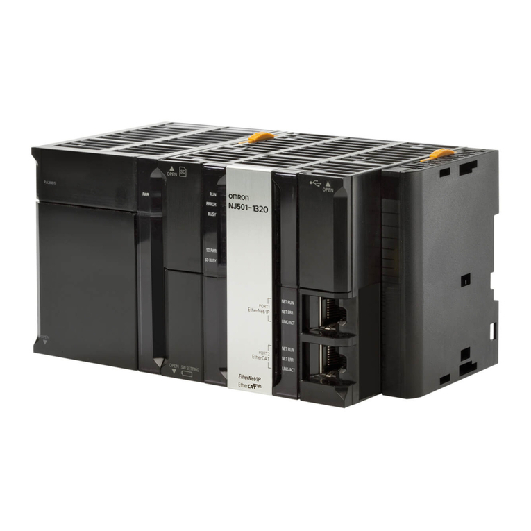
ESTERS ELEKTRONIK FMP 1836 User manual

P
=
Speed Pressure Flow Rate Temperature
Instruction Manual IM 109 E
Page
1
Phone:
+49 (0)
6021
–
45 80
-
0
Fax: +49 (0) 6021 – 45 80 -0
Esters Elektronik Gmb
H
Hafenrandstr. 14 · D-63 41 Aschaffenburg
eMail:
info
@
esters.de
Internet: http://www.esters.de
Rev.-Nr.: IM 109 E V0.1-2017-06-26; FW 4.12
INSTRUCTION MANUAL IM 109 E
Device: FMP 1836 - with LCD display
measurement computer for limit value monitoring of
frequency input
Content: Instruction manual
Rev.-No.: IM 109 E V0.1-2017-06-26; FW 4.12

P
=
Speed Pressure Flow Rate Temperature
Instruction Manual IM 109 E
Page
2
Phone:
+49 (0)
6021
–
45 80
-
0
Fax: +49 (0) 6021 – 45 80 -0
Esters Elektronik Gmb
H
Hafenrandstr. 14 · D-63 41 Aschaffenburg
eMail:
info
@
esters.de
Internet: http://www.esters.de
Rev.-Nr.: IM 109 E V0.1-2017-06-26; FW 4.12
User information
-
Prior to installing the equipment or before attempting initial start-up, please read this manual
thoroughly.
-
Please ensure to observe all information and warnings provided in this manual.
-
The serial number of the equipment can be found on the identification plate. You will need this
information when ordering spare parts. The plate is attached to the outside of the device.
-
Installation, start-up and maintenance may only be performed by an electrician. The local guidelines
of the place of installation have to be observed.
-
Maintenance may only be performed under dead-voltage conditions for personal security reasons.
-
In order of guarantee operational safety, only the manufacturer's original spare parts shall be
installed.
-
Operating the equipment for purposes other than its intended use shall void all warranty claims and
product liability. Noncompliance with the intended use refers to but is not limited to improper
installation, start-up, operation, maintenance and neglecting the information provided in this
manual.
-
The device must be integrated into the lightening protection concept of the plant.
Please ensure to operate this device only in accordance with this manual.
Departure from these instructions will void and nullify all warranty claims and
jeopardizes the operating safety of the device.
We reserve the right to engineering changes, which may necessitate deviations from the current data
provided in this manual. Should you require additional information or questions arise that are not
sufficiently covered in this manual, please contact us at the following address:
Imprint
Esters Elektronik GmbH
Hafenrandstr. 14
D
-
63 41
Aschaffenburg
Tel.: +49 (0)
6021
–
45 80
-
0
Fax: +49
(0)
6021
–
45 80
-
0
eMail: [email protected]e
Internet: www.esters.de
Copyright
This manual is protected by copyright.
Duplication or distribution is not permitted without express written approval.
© Esters Elektronik GmbH,
Aschaffenburg

P
=
Speed Pressure Flow Rate Temperature
Instruction Manual IM 109 E
Page
3
Phone:
+49 (0)
6021
–
45 80
-
0
Fax: +49 (0) 6021 – 45 80 -0
Esters Elektronik Gmb
H
Hafenrandstr. 14 · D-63 41 Aschaffenburg
eMail:
info
@
esters.de
Internet: http://www.esters.de
Rev.-Nr.: IM 109 E V0.1-2017-06-26; FW 4.12
Table of content
Introduction ___________________________________________________________________ 4
1.1 Operating instructions, general information ________________________________________ 4
1.2 Goods receipt inspection, transportation, storage ___________________________________ 4
2 Warranty ______________________________________________________________________ 5
3 General information _____________________________________________________________ 6
3.1 Benefits at a glance ____________________________________________________________ 6
4 Installation / servicing / maintenance_______________________________________________ 7
5 Technical specifications __________________________________________________________ 8
5.1 Input _______________________________________________________________________ 8
5.2 Relay _______________________________________________________________________ 8
5.3 Electrical values ______________________________________________________________ 9
5.4 Environmental influences _______________________________________________________ 9
5.5 Mechanical values ____________________________________________________________ 9
5.6 Display and housing __________________________________________________________ 10
5. Interfaces __________________________________________________________________ 10
5.8 Software and recorder ________________________________________________________ 11
6 Device types __________________________________________________________________
6.1 Optional device functions and housing ___________________________________________ 12
7 Operating panel _______________________________________________________________ 3
.1 Layout of LCD display _________________________________________________________ 13
.2 Measured value display _______________________________________________________ 14
8 Operating overview ____________________________________________________________ 5
8.1 Operating overview in measurement mode________________________________________ 15
8.2 Operating overview in configuration mode ________________________________________ 15
8.3 Operating overview in programming mode ________________________________________ 16
9 Configuration function codes_____________________________________________________ 6
9.1 Types of configuration function codes ____________________________________________ 1
9.2 Description of individual configuration function codes _______________________________ 18
0 Configuration using the software E3DM ____________________________________________ 2
Monitoring with E3DM__________________________________________________________ 22
2 Connecting diagram ____________________________________________________________ 25

P
=
Speed Pressure Flow Rate Temperature
Instruction Manual IM 109 E
Page
4
Phone:
+49 (0)
6021
–
45 80
-
0
Fax: +49 (0) 6021 – 45 80 -0
Esters Elektronik Gmb
H
Hafenrandstr. 14 · D-63 41 Aschaffenburg
eMail:
info
@
esters.de
Internet: http://www.esters.de
Rev.-Nr.: IM 109 E V0.1-2017-06-26; FW 4.12
Introduction
. Operating instructions, general information
These operating instructions are intended for the use of the device and meant to provide support during
the installation, operation, and maintenance.
The structure of the document shall make this easy. Important text is highlighted.
Symbols
The following symbols are used in these operating instructions in order to highlight text that requires
special attention.
Notes
This arrow points to features that require your special attention.
Caution
This symbol points to important text.
Noncompliance or disregard may cause damage to components or destruction to
parts of the system.
Warning!
This symbol points to important text. Noncompliance will place the life and health
of persons at risk.
Reference
This symbol refers to additional information available in other manuals, chapters,
or sections.
.2 Goods receipt inspection, transportation, storage
-
Ensure the packaging is not damaged!
-
Any damaged packaging must be reported to the supplier.
-
Retain any damaged packaging until the matter has been resolved.
-
Ensure the package's content is not damaged!
-
Any damaged part received must be reported to the supplier.
-
Retain any damaged goods until the matter has been resolved.
-
Use the delivery documents to check the received goods and compare the goods with your order to
ensure completeness. For storage and transport purposes, the equipment must be packed with care
to prevent damage caused by impact or humidity. Only the original packaging can ensure optimal
protection. Furthermore, compliance with all allowable ambient conditions is mandatory (section 4).
-
If you have any questions, please contact your supplier or the respective distribution centre.

P
=
Speed Pressure Flow Rate Temperature
Instruction Manual IM 109 E
Page
5
Phone:
+49 (0)
6021
–
45 80
-
0
Fax: +49 (0) 6021 – 45 80 -0
Esters Elektronik Gmb
H
Hafenrandstr. 14 · D-63 41 Aschaffenburg
eMail:
info
@
esters.de
Internet: http://www.esters.de
Rev.-Nr.: IM 109 E V0.1-2017-06-26; FW 4.12
2 Warranty
The devices were built in compliance with current directives and have left the factory in technically
flawless condition.
In the unlikely event that you still may have reasons for a complaint and the fault can be traced to a
factory error, we shall correct any defects at no additional charge. However, in such case, it is your
responsibility to report the damage immediately after detection and/or within our permitted warranty
period.
Damage caused due to improper use or as a result of noncompliance with these operating instructions, is
excluded from this warranty.
The warranty period is 12 months. Unless otherwise agreed upon, the warranty period for spare parts is
12 months as well. The fulfilment of warranty claims shall not extend the warranty period.
The warranty shall become null and void if the measurement module has been opened, unless otherwise
expressly stated in the operating instructions or for maintenance purposes only. This shall also apply if
serial numbers have been changed, damaged, or removed.
Any repairs, adjustments or similar tasks necessary besides warranty performances shall be without
charge. Other services, including transport and packaging shall be invoiced.
Unless liability is mandatory by law, further claims, in particular claims based on damages that do not
concern the delivered components, are excluded.
Services provided after the warranty period
Of course, we will be pleased to assist you once the warranty has expired. You can reach us directly by
calling.
Contact:
Phone:
+49 (6021) 45 80
-
0
Fax:
+49 (6021) 45 80
-
20
eMail:

P
=
Speed Pressure Flow Rate Temperature
Instruction Manual IM 109 E
Page
6
Phone:
+49 (0)
6021
–
45 80
-
0
Fax: +49 (0) 6021 – 45 80 -0
Esters Elektronik Gmb
H
Hafenrandstr. 14 · D-63 41 Aschaffenburg
eMail:
info
@
esters.de
Internet: http://www.esters.de
Rev.-Nr.: IM 109 E V0.1-2017-06-26; FW 4.12
3 General information
The FMP 1836 is a 2-channel device “A” and “B” for monitoring the limit value of frequency inputs. Two
signal converters SC 500 are connected to port 1 and 2. Each channel monitors 3 limit values. The device
has implemented relays. The relays are fixed to limitators for limit monitoring. Freely configurable
signal sources can be applied to the limitators.
3. Benefits at a glance
Application areas
Benefits at a glance
-
Actual value for analog speed control
-
Paper, fiber, film, steel and crane industry
-
Turbines
-
Generators
-
Centrifuges
-
Emergency diesel
-
Textile machines
-
Test stands
-
Agitators
-
ntegrated recorder function for logging of
measurement values (2 GB ring storage)
-
Linearisation via a maximum of 12 support points
-
Up to three limit values / relays / changeovers
-
2 digital inputs for start and stop function for
control via PLC
-
Integration in IT networks via Ethernet/IP for
remote data transfer
-
Integration in industry bus systems, e.g. Profibus
DP, Modbus RTU, Modbus TCP, Profinet
-
Up to 12 measuring computers can be
networked via an internal CAN bus
-
Persistent data retention of total counter reading
in case of power loss for a period of up to 5 years

P
=
Speed Pressure Flow Rate Temperature
Instruction Manual IM 109 E
Page
Phone:
+49 (0)
6021
–
45 80
-
0
Fax: +49 (0) 6021 – 45 80 -0
Esters Elektronik Gmb
H
Hafenrandstr. 14 · D-63 41 Aschaffenburg
eMail:
info
@
esters.de
Internet: http://www.esters.de
Rev.-Nr.: IM 109 E V0.1-2017-06-26; FW 4.12
4 Installation / servicing / maintenance
This device has been designed for direct mounting on a DIN rail. The monitor can be mounted directly in
a switch cabinet or in a separately available housing. Installation may only be performed by specialist,
trained personnel.
Servicing and maintenance activities may only be performed by Esters Elektronik GmbH technicians or by
persons trained by Esters Elektronik GmbH.
Contact:
Phone:
+49 (6021) 45 80
-
0
Fax:
+49 (6021) 45 80
-
20
eMail:

P
=
Speed Pressure Flow Rate Temperature
Instruction Manual IM 109 E
Page
8
Phone:
+49 (0)
6021
–
45 80
-
0
Fax: +49 (0) 6021 – 45 80 -0
Esters Elektronik Gmb
H
Hafenrandstr. 14 · D-63 41 Aschaffenburg
eMail:
info
@
esters.de
Internet: http://www.esters.de
Rev.-Nr.: IM 109 E V0.1-2017-06-26; FW 4.12
5 Technical specifications
The FMP 1836-8001 is available as 2-channel unit. The device series has been constructed according to
the modular principle. The principle allows configuration of inputs and outputs as well as of interfaces
and software options according to individual usage and operating system requirements.
The section on technical specifications provides an overview in respect of the series.
5. Input
I
NPUT
1
(
CHANNEL
“A”)
frequency
„A“:
10 - 1 kHz with 5% duty cycle, impulse length > 500 ms
I
NPUT
2
(
CHANNEL
“B”)
frequency
„B“:
10 - 1 kHz with 5% duty cycle, impulse length > 500 ms
5.2 Relay
K1:
LIMIT VALUE
„MIN“
CHANNEL
„A“
NO contact
, 30 V, AC, 1A
inductive
K2:
LIMIT VALUE
„BAND“
CHANNEL
„A“
NO contact
, 30 V, AC, 1A
inductive
K3:
LIMIT VALUE
„MAX“
CHANNEL
„A“
NO contact
, 30 V, AC, 1A
inductive
K4:
LIMIT VALUE
„MIN“
CHANNEL
„B“
NO contact
, 30 V, AC, 1A
inductive
K5:
LIMIT VALUE
„BAND“
CHANNEL
„B“
NO contact
, 30 V, AC, 1A
inductive
K6:
LIMIT VALUE
„MAX“
CHANNEL
„B“
NO contact
, 30 V, AC, 1A
inductive
K :
LIMIT VALUE
„NOTCH“
CHANNEL
„A“
NO contact
, 30 V, AC, 1A
inductive
K8:
DEVICE STATUS
NO contact
, 30 V, AC, 1A
inductive

P
=
Speed Pressure Flow Rate Temperature
Instruction Manual IM 109 E
Page
9
Phone:
+49 (0)
6021
–
45 80
-
0
Fax: +49 (0) 6021 – 45 80 -0
Esters Elektronik Gmb
H
Hafenrandstr. 14 · D-63 41 Aschaffenburg
eMail:
info
@
esters.de
Internet: http://www.esters.de
Rev.-Nr.: IM 109 E V0.1-2017-06-26; FW 4.12
5.3 Electrical values
5.4 Environmental influences
5.5 Mechanical values
T
ORQUE CLAMPS
0.15 Nm max.
A
CCURACY
± 0.05% unit value ± 1 digit at 23°C
M
AINS SUPPLY
(
STANDARD
)
24 V, DC ± 3V
C
URRENT CONSUMPTION
max. 1.25 A
Fuse protection by means of 3A preliminary fuse or inherently
safe mains adaptor
P
OWER CONSUMPTION
max.
30 VA
E
XTERNAL MAINS ADAPTOR
24 V/DC
A
MBIENT TEMPERATURE
-
10 to +55°C
S
TORAGE TEMPERATURE
-
20 to +85°C
T
EST VOLTAGE
3 kV
H
UMIDITY CLASS
E
-
DIN 40040
E
LECTROMAGNETIC COMPATIBILITY
as per DIN EN 61000
C
LIMATIC CLASS
as per IEC 60 654-1 Class B2 / EN 1434 Class "C"
(no condensation permitted)
E
LECTRICAL SAFETY
as per IEC 61010-1: Environment < 2000 m height above NN
O
VERVOLTAGE CATEGORY
IEC 61010
-
1, Protection class II, Overvoltage category II
D
EGREE OF CONTAMINATION
Degree
of contamination 2

P
=
Speed Pressure Flow Rate Temperature
Instruction Manual IM 109 E
Page
10
Phone:
+49 (0)
6021
–
45 80
-
0
Fax: +49 (0) 6021 – 45 80 -0
Esters Elektronik Gmb
H
Hafenrandstr. 14 · D-63 41 Aschaffenburg
eMail:
info
@
esters.de
Internet: http://www.esters.de
Rev.-Nr.: IM 109 E V0.1-2017-06-26; FW 4.12
5.6 Display and housing
5.7 Interfaces
RS
232
9
-
pin connection
to update the firmware
USB Mini USB-connection (5-pin, USB 2.0) for configuration and data
transfer through PC
CAN
-
BUS
(O
PTIONAL
)
Internal communication of up to 12 curable devices
P
ROFIBUS
DP
(O
PTIONAL
)
Data transmision via Profibus
-
DP protocol
M
ODBUS
-
RTU
(O
PTIONAL
)
Data transmision via MODBUS
-
RTU protocol
M
ODBUS
-
TCP
(O
PTIONAL
)
Data transmision via MODBUS
-
TCP protocol
E
THERNET
(O
PTIONAL
) Integration into the IT-network for configuration and data
transfer through PC
D
ISPLAY
6-digit LCD display for flow rate in Nm³/h
-digit LCD display in Nm³
LCD height 8 mm
S
TANDARD HOUSING
DIN
RAIL MOUNTING
Modular clamp housing made from Makrolon
Fire classification as per UL 94:V-D
35 mm standard rail as per DIN EN 50022
Dimensions: 100 (W) x 100 (H) x 10 (D) mm
Protection class IP 20
F
IELD HOUSING
(
OPTION
M104) Dimensions: 343 (W) x 330 (H) x 210 (D) mm
Wall mounting
Protection class IP 65
F
IELD HOUSING WITH
EX-
ZONE
(
OPTION
M105)
Dimensions: 385.5 (W) x 48 (H) x 210 (D) mm
Wall mounting
Protection class IP 65
T
OTAL WEIGHT
:
FMP
1836
INCL
.
F
IELDHOUSING
M104
INCL
.
F
IELDHOUSING
M105
480 g
3650 g
5650 g

P
=
Speed Pressure Flow Rate Temperature
Instruction Manual IM 109 E
Page
11
Phone:
+49 (0)
6021
–
45 80
-
0
Fax: +49 (0) 6021 – 45 80 -0
Esters Elektronik Gmb
H
Hafenrandstr. 14 · D-63 41 Aschaffenburg
eMail:
info
@
esters.de
Internet: http://www.esters.de
Rev.-Nr.: IM 109 E V0.1-2017-06-26; FW 4.12
5.8 Software and recorder
E3DM Configuration software for Microsoft Windows
(32
-
Bit)
R
ING BUFFER
2 GB ring buffer
Integrated recorder function for logging measurement values
over a period of several years
6 Device types
FMP
-
1836
-
8001
I
NPUT
:
1:
frequency
„A“
•
2:
frequency
„B“
•
3:
4:
5:
6:
:
8:
R
ELAY
:
K1 (
NO contact
):
l
imit value
„MIN“
c
hannel
„A“
•
K2 (
NO contact
):
l
imit value
„BAND“
c
hannel
„A“
•
K3 (
NO contact
):
l
imit value
„MAX“
c
hannel
„A“
•
K4 (
NO contact
):
l
imit value
„MIN“
c
hannel
„B“
•
K5 (
NO contact
):
l
imi
t value
„BAND“
c
hannel
„B“
•
K6 (
NO contact
):
l
imit value
„MAX“
c
hannel
„B“
•
K (
NO contact
):
l
imit value
„NOTCH“
c
hannel
„A“
•
K8 (
NO contact
):
device status
•

P
=
Speed Pressure Flow Rate Temperature
Instruction Manual IM 109 E
Page
12
Phone:
+49 (0)
6021
–
45 80
-
0
Fax: +49 (0) 6021 – 45 80 -0
Esters Elektronik Gmb
H
Hafenrandstr. 14 · D-63 41 Aschaffenburg
eMail:
info
@
esters.de
Internet: http://www.esters.de
Rev.-Nr.: IM 109 E V0.1-2017-06-26; FW 4.12
6. Optional device functions and housing
GDR
1836-8001-00
0
no selection
1
Interfa
ce PROFIBUS
-
DP
2
Interface Modbus
-
RTU
4
Interface Modbus
-
TCP
0
no selection
1
Interface CAN
-
Bus
4
Interface Ethernet TCP/IP
5
Interface CAN
-
Bus, Interface Ethernet TCP/IP
8
Ring storage 2 GB (data recorder)
9
Ring buffer 2 GB (data
recorder), Interface CAN
-
Bus
C
Ring buffer 2 GB (data recorder), Interface Ethernet TCP/IP
D
Ring buffer 2 GB (data recorder), Interface CAN
-
Bus, Interface Ethernet
TCP/IP
H
OUSING
M104
Field housing for wall mounting, protection class IP 65

P
=
Speed Pressure Flow Rate Temperature
Instruction Manual IM 109 E
Page
13
Phone:
+49 (0)
6021
–
45 80
-
0
Fax: +49 (0) 6021 – 45 80 -0
Esters Elektronik Gmb
H
Hafenrandstr. 14 · D-63 41 Aschaffenburg
eMail:
info
@
esters.de
Internet: http://www.esters.de
Rev.-Nr.: IM 109 E V0.1-2017-06-26; FW 4.12
7 Operating panel
7. Layout of LCD display
The following figure provides information on the layout of the LCD display of the device.
Display
value 2
(line 2)
Display
value 1
(line 1)
Display
menu-no.
Display
device status
(line 4a)
Display
programming or error code
(line 4b)
Display
decription value 1
(line 3)
Button „ESC“
Button „UP“
Button „DOWN“
Button „SCROLL“
Button „OK“
Display
dimension
unit
Display
Channel
Device type
Device descripition

P
=
Speed Pressure Flow Rate Temperature
Instruction Manual IM 109 E
Page
14
Phone:
+49 (0)
6021
–
45 80
-
0
Fax: +49 (0) 6021 – 45 80 -0
Esters Elektronik Gmb
H
Hafenrandstr. 14 · D-63 41 Aschaffenburg
eMail:
info
@
esters.de
Internet: http://www.esters.de
Rev.-Nr.: IM 109 E V0.1-2017-06-26; FW 4.12
7.2 Measured value display
Four-line LCD display, whereby lines 1 to 3 show a maximum of 10 digits.
Measured value display
S
CREE
N
C
ONTENT OF LINE
1
(
VALUE
1) C
ONTENT OF LINE
2
(
VALUE
2) C
ONTENT OF LINE
3
(
VALUE
3)
1
frequency „A“ [Hz]
rotational speed „A“ [min
-
1] or
[rpm]
channel A
2
frequency „B“ [Hz]
rotational speed „B“ [min
-
1] or
[rpm]
channel B
C
ONTENT OF LINE
3
Plain te
xt in German, according to content of line 1.
C
ONTENT OF LINE
4
A
D
EVICE
STATUS
DISPLAY
OK The device is ready for operation and is running
in standard function mode; no errors present.
M An application error has occurred,
i.e. a function failure was
detected.
E
A system error (hardware defect, powering up
error etc.) was detected, i.e. the device can no
longer guarantee functionality. Please contact
the service department.
C
ONTENT OF LINE
4
B
D
ISPLAY OF
PROGRAMMING CODE
The code display can be found to the right of the status
display, and comprises a 9-digit LCD display. The line
contains the configuration function codes described
below.
D
EVICE STATUS
"M"
OR
"E"
In the event of a system error (= "E"), a 4-digit error code
is displayed
Shows
a malfunction or system error.
K
EYS ON FRONT
The five keys on the front Abort, Arrow down, Arrow up, OK and
Scroll can be used for operation.

P
=
Speed Pressure Flow Rate Temperature
Instruction Manual IM 109 E
Page
15
Phone:
+49 (0)
6021
–
45 80
-
0
Fax: +49 (0) 6021 – 45 80 -0
Esters Elektronik Gmb
H
Hafenrandstr. 14 · D-63 41 Aschaffenburg
eMail:
info
@
esters.de
Internet: http://www.esters.de
Rev.-Nr.: IM 109 E V0.1-2017-06-26; FW 4.12
8 Operating overview
Programming can be performed directly at the device or via a PC USB interface by using the configuration
software E3DM (see instructions for use IM 50 D).
As soon as voltage is applied, the device is in measuring mode.
Pressing the key for at least 5 seconds causes the flow correction calculator to switch to the
configuration mode, in which the configuration is displayed or can be programmed. The measured value
display is switched off and the first configuration code appears in the programming code display.
8. Operating overview in measurement mode
In measurement mode, operation is performed by means of the five keys on the front according to the
following scheme:
8.2 Operating overview in configuration mode
A
BORT
Stops automatically measurement value switching
The measured value display mode currently selected remains active
A
RROW DOWN
Switching of measured value display mode
Interruption of automatic run-through of measured value display modes
Auto mode with key
A
RROW UP
Switching of measured value display mode
Interruption of automatic run-through of measured value display modes
Auto mode with key
OK No effect in measurement mode
S
CROLL
5-second configuration mode:
Current configuration
Programming mode
Auto mode for measured value display
A
BORT
Switches from configuration mode to measurement mode
A
RROW DOWN
Selection of configuration function
A
RROW UP
Selection of configuration function
OK Pressing the key has no effect in the configuration mode
S
CROLL
Switches programming mode for configuration function:
Setting via or
Confirmat
ion with

P
=
Speed Pressure Flow Rate Temperature
Instruction Manual IM 109 E
Page
16
Phone:
+49 (0)
6021
–
45 80
-
0
Fax: +49 (0) 6021 – 45 80 -0
Esters Elektronik Gmb
H
Hafenrandstr. 14 · D-63 41 Aschaffenburg
eMail:
info
@
esters.de
Internet: http://www.esters.de
Rev.-Nr.: IM 109 E V0.1-2017-06-26; FW 4.12
8.3 Operating overview in programming mode
Pressing the key switches the displayed configuration function code to programming mode. The first
line of the measured value display shows the previous value of the configuration function. The new value
can be entered in the second line of the measured value display.
9 Configuration function codes
As described in 8, the device can be switched to configuration mode by pressing the key for at least 5
seconds. The measured value display is switched off and the first configuration code appears in the
programming code display. Pressing the keys or switches between the configuration function
codes listed below. Once the end or beginning of the code list has been reached, no more switching takes
place. Switching can only take place in the opposite direction.
Please note:
The configuration function codes may be protected with a 4-digit code for the various user groups. In this
case, you will only be able to view the configuration function codes for the user group ALL. For enabling
user groups OEM or SRV, you need to enter the corresponding code under configuration function code
50 – PIN entry.
Functions within configuration codes
-
You can change the preset values by pressing the key within a configurable configuration code.
-
By pressing the keys or , you can continue switching the relevant display in the configuration
menu. Fast scrolling can be performed by holding down the key. The longer you press the key, the
faster the display changes. The value selected remains active until the keys or are pressed or
fine-tuning has taken place or programming has been confirmed by means of the key.
-
Where programming is not completed within the preset time or is cancelled by pressing the key,
the timeout function cause programming to be aborted. The change is not stored.
A
BORT
Switches from configuration mode to measurement mode.
A
RROW DOWN
Selection of configuration function
A
RROW UP
Selection of configuration function
OK
Pressing the
confir
ms the programming
S
CROLL
Switches Programming mode to configuration function:
Setting via or
Confirmation with

P
=
Speed Pressure Flow Rate Temperature
Instruction Manual IM 109 E
Page
1
Phone:
+49 (0)
6021
–
45 80
-
0
Fax: +49 (0) 6021 – 45 80 -0
Esters Elektronik Gmb
H
Hafenrandstr. 14 · D-63 41 Aschaffenburg
eMail:
info
@
esters.de
Internet: http://www.esters.de
Rev.-Nr.: IM 109 E V0.1-2017-06-26; FW 4.12
9. Types of configuration function codes
C
ODE
D
ESCRIPTION
A
CCESS
A
DJUSTMENT RANGE
S
TEP
0001 Device ID ALL - -
0003 SW version & BUILD ID ALL - -
0004 SW version communication subsystem
1)
/
Ethernet subsystem
1)
ALL - -
0005 Operating hours ALL - -
0006 Serial number ALL - -
000 Ethernet IP address
1)
ALL - -
0008 Ethernet subnet mask
1)
ALL - -
0009 Ethernet gateway address
1)
ALL - -
0010 Ethernet MAC address
1)
ALL - -
0015 Trigger Ethernet broadcast
1)
ALL 0-1 1
0020 Display device time ALL - -
0050 PIN entry
2)
ALL 0000-9999 1
0051 Service PIN
2)
SRV 0000-9999 1
0052 OEM PIN
2)
OEM 0000-9999 1
0053 Parameter code
2)
SRV 0000-9999 1
0054 Parameter index
2)
SRV 0000-9999
0055 Parameter value
2)
SRV -2
31
±(2
31
-1) 1*
The codes 0056 to 6049 are nor used for the device FMP
6050 Number of poles A SRV 1
6051 Number of poles B SRV 1

P
=
Speed Pressure Flow Rate Temperature
Instruction Manual IM 109 E
Page
18
Phone:
+49 (0)
6021
–
45 80
-
0
Fax: +49 (0) 6021 – 45 80 -0
Esters Elektronik Gmb
H
Hafenrandstr. 14 · D-63 41 Aschaffenburg
eMail:
info
@
esters.de
Internet: http://www.esters.de
Rev.-Nr.: IM 109 E V0.1-2017-06-26; FW 4.12
9.2 Description of individual configuration function codes
Configuration function code 000 - Device ID
Device ID is shown in the measured value display.
The device ID cannot be change d; it is specified ex factory.
Access group:
User identification by means of a P
IN is not required.
Configuration function code 0002 - Available options
The available options are shown in the measured value display. The options are preceded by a hyphen in
each case, resulting in several options being separated from each other as well. The end of the list of
available options is represented by two consecutive decimal points. If the list of available options is too
long to be shown in the first line of the measured value display, pressing the keys or will continue
switching the display.
The available options cannot be changed; they are specified ex factory.
Access group:
ALL
Configuration function code 0003 - SW version & BUILD ID
The first line of the measured value display shows the software version and the second line shows the
BUILD ID of the software installed in the device.
The software version and BUILD ID cannot be changed; the information is specified ex factory.
Access group:
ALL
Configuration function code 0004 - SW version communication subsystem
Where this is available as an option, the software version of the PLC is displayed in the first line. The
second line contains the software version for the Ethernet subsystem.
The software version communication subsystem cannot be changed; the information is specified ex
factory.
Access group:
ALL
Configuration function code 0005 - Operating hours
The first line of the measured value display shows the total counter reading for the operating hours.
The operating hours reading cannot be changed.
Access group:
ALL
Configuration function code 0006 - Serial number
The first line displays the serial number.
The serial number cannot be changed.
Access group:
ALL

P
=
Speed Pressure Flow Rate Temperature
Instruction Manual IM 109 E
Page
19
Phone:
+49 (0)
6021
–
45 80
-
0
Fax: +49 (0) 6021 – 45 80 -0
Esters Elektronik Gmb
H
Hafenrandstr. 14 · D-63 41 Aschaffenburg
eMail:
info
@
esters.de
Internet: http://www.esters.de
Rev.-Nr.: IM 109 E V0.1-2017-06-26; FW 4.12
Configuration function code 0007 - Ethernet IP address
Where this is available as an option, the IP address of the device is displayed.
The IP address cannot be changed.
Access group:
ALL
Configuration function code 0008 - Ethernet subnet mask
Where this is available as an option, the Ethernet subnet mask of the device is displayed. The subnet
mask cannot be changed.
Configuration function code 0009 - Ethernet gateway address
Where this is available as an option, the Ethernet gateway address of the device is displayed.
Access group:
ALL
The gateway address cannot be changed.
Configuration function code 00 0 - Ethernet MAC address
Where this is available as an option, the Ethernet MAC address of the device is displayed.
The MAC address cannot be changed.
Access group:
ALL
Configuration function code 00 5 - Trigger Ethernet broadcast
Where the Ethernet option is available, EDIT is shown in the first line of the display. The display in the
second line 0000 can be edited.
The subnet mask cannot be changed.
Access group:
ALL
Adjustment range:
0
-
1
Step:
1
Configuration function code 0020 - Show device time
The first line of the display shows the device time comprising the date and time.
The device time cannot be changed.
Access group:
ALL
Configuration function code 005 - PIN entry
Where identification of the user was correctly completed by entering the user PIN, all configuration
function codes for the access group ALL are enabled for viewing/modifying until the configuration mode
is exited.
Access group:
ALL
Adjustment range:
0000 ... 9999
Step:
1
Access group:
ALL

P
=
Speed Pressure Flow Rate Temperature
Instruction Manual IM 109 E
Page
20
Phone:
+49 (0)
6021
–
45 80
-
0
Fax: +49 (0) 6021 – 45 80 -0
Esters Elektronik Gmb
H
Hafenrandstr. 14 · D-63 41 Aschaffenburg
eMail:
info
@
esters.de
Internet: http://www.esters.de
Rev.-Nr.: IM 109 E V0.1-2017-06-26; FW 4.12
Configuration function code 0052 - OEM PIN
Where identification of the user of the OEM user group was correctly completed by entering the OEM
PIN, all configuration function codes for the access groups ALL, SRV and OEM are enabled for
viewing/modifying until the configuration mode is exited.
Access group:
OEM
Adjustment range:
0000 … 9999
Step:
1
Configuration function code 0053 – Parameter code
In order to select the parameter, the parameter code has to be set in the input mask:
Access group:
SRV
Adjustment range:
0000
–
9999
Step:
1
Configuration function code 0055 – Parameter code
In order to select the parameter, the parameter code has to be set in the input mask:
Access group:
SRV
Adjustment range:
0000
-
9999
Step:
1
Other manuals for FMP 1836
1
Table of contents
