manuals.online logo
Brands
  1. Home
  2. •
  3. Brands
  4. •
  5. Full Gauge
  6. •
  7. Controllers
  8. •
  9. Full Gauge MT-530 Super User manual

Full Gauge MT-530 Super User manual

Controles de humedad temperatura con y salida a PC MT-530 SUPER FULL-GAUGE manual ingles www.viaindustrial.com
MT-530Super
MT530SP03-06T-12427
MT-530
%uper
THERM
HUMID AUX BUZZ
CONTROLLER
AND
DIGITAL
INDICATOR
TEMPERATURE
AND
HUMIDITY
WITH
SERIAL
COMMUNICATION
TO
SITRAD
Ver.03
1. DESCRIPTION
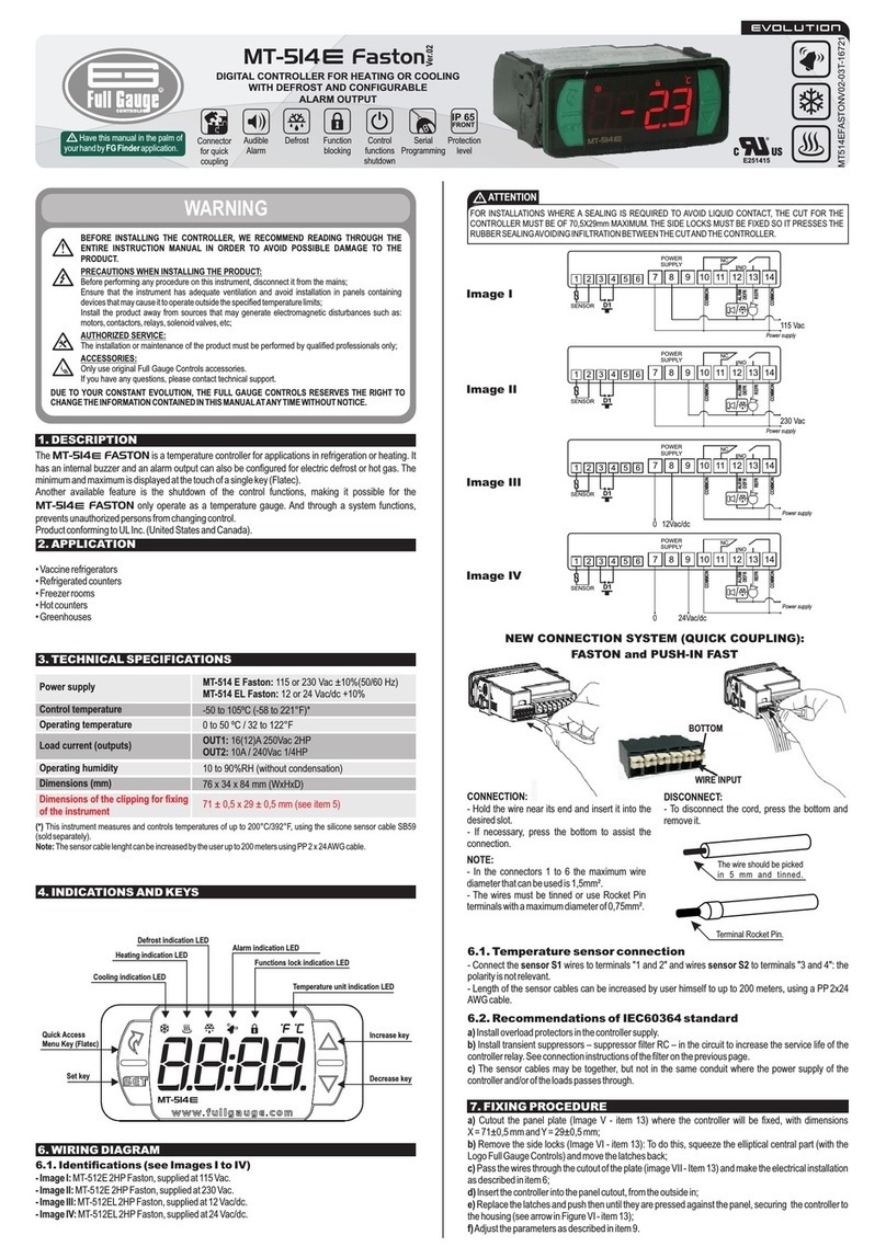
The MT-530
%uper
features three outputs: one for temperature control, one for humidity control and
athird auxiliary output that can be configured to command asecond stage temperature or humidity
control.This controller is indicated for low and average relative humidity (10-85% non-condensing), and
italsofeaturesanaudiblesignal(buzzer)thatcanbeactivatedasanalarmoratimer(cyclictimer).
Itssensorsoftemperatureandhumidityarejoinedinanonlybulb,thatreducesthespaceinwiringofthe
installation.
E251415
4. CONFIGURATIONS
4.1 -Temperature and humidity adjust (SETPOINTS):
-Press
SET
for 2seconds until appears, then release it.The indication and the adjusted
temperatureforTHERMoutputwillappear.
-Usethekeys and tochangethevalueandthenpress
SET
torecordit.
-Now andadjustedhumidityforHUMIDoutputwillappear.
-Usethekeys and tochangethevalueandthenpress
SET
again.
-Then,iftheAUXoutputissettocontrol(F14=0,1,2or3)itmayappear or .
TheinstrumenthasserialcommunicationforconnectionwiththeSITRAD®viaInternet. -Usethekeys and tochangethevaluefortheAUXoutputandthenpress
SET
torecordit.
ProductcomplieswithULInc.(UnitedStatesandCanada).
2. APPLICATION
•Humidificators/dehumidificators
•Grainsdrying
•Laboratories
•Surgicalrooms
•Climatizedcellars
•Informationtechnologycenters
*Forhighpercentageofhumidityinthepresenceofwatercondensation,usethemodelRiAHC-80plus.
3. TECHNICAL SPECIFICATIONS
-PowerSupply:
MT-530Super-115or230Vac±10%(50/60Hz)
MT-530LSuper-12or24Vac/dc
-ControlTemperature:
-10to70.0ºC±1.5°C(withresolutionof0.1°C)
14to158ºF
±3°F(withresolutionof1°F)
-ControlHumidity:
10to85%RH
±5%RH(withresolutionof0.1%RH)
-Loadcurrent:
5(3)A/250Vac1/8HP(eachoutput)
-Operationtemperature:
0to50°C
32to122°F
-Operationhumidity:
10to85%RH(withoutcondensation)
-Dimensions:
71x28x71mm
4.4 -Parameters description
4.2 -Parameters configuration
-Access the function F01 pressing simultaneously the keys and for 2seconds until appearing
,releasingafterthat.Soonitwillappear ,andthenpress
SET
(shorttouch).
-Usethekeys and toenteracesscode(123)and,whenreadypress
SET
toconfirm.
-Usethekeys and toaccessthedesiredfunction.
-Afterselectingthefunction,press
SET
(shorttouch)tovisualizethevalueconfiguredforthatfunction.
-Use the keys and to change the value, and when ready,press
SET
to memorize the configured
valueandreturntothemenuoffunctions.
-Toleavethemenuoffunctionsandreturntonormaloperation,press
SET
untilappear .
CELSIUS
FAHRENHEIT
Fun
Description
Min.
Max.
Unit
Standard
Min.
Max.
Unit
Standard
Access code: 123 (one hundred and twenty-three)
Thermostat operation mode (THERM output)
Minimum setpoint allowed to the user
(thermostat)
Maximum setpoint allowed to the user (thermostat)
Control differential (hysteresis) of the thermostat
Minimum delay to turn the thermostat output on
-99
0-refrig.
-10.0
-10.0
0.1
0
999
1-heat
70.0
70.0
20.0
999
-
-
°C
°C
°C
seg.
-
0-refrig.
-10.0
70.0
1.5
0
-99
0-refrig.
14
14
1
0
999
1-heat
158
158
36
999
-
-
°F
°F
°F
seg.
-
0-refrig.
14
158
3
0
Humidistat operation mode (HUMID output) 0-dehum. 1-hum. -1-hum. 0-dehum.
1-umid. -1-hum.
Minimum setpoint allowed to the user (humidistat)
Maximum setpoint allowed to the user (humidistat)
Control differential (hysteresis) of the humidistat
Minimum delay to turn the humidistat output on
Humidity output (time on)
Humidity output (time off)
Auxiliary output operation mode (AUX)
Minimum setpoint allowed to the user (AUX output)
Maximum setpoint allowed to the user (AUX output)
Control differential (hysteresis) of the AUX output
Minimum delay to turn the AUX output on
Time base of AUX output timer
AUX output (time on)
AUX output (time off)
Low room temperature alarm
High room temperature alarm
Low room humidity alarm
High room humidity alarm
Minimum delay to turn the AUX output on (alarm mode)
Buzzer operation mode
Acting point of Buzzer by low temperature
Acting point of Buzzer by high temperature
Acting point of Buzzer by low humidity
Acting point of Buzzer by high humidity
Maximum time of the activated THERM output to activate the alarm
Maximum time of the activated HUMID
output to activate the alarm
Maximum time of the activated AUX output to activate the alarm
Buzzer
time on
Buzzer time off
Inhibition time of Buzzer during electrical supply
Output status in case of alarm
Display mode
Temperature display offset
Humidity display offset
Network equipment address RS-485
0
0
0.1
0
0
0
0
0
0
0.1
0
0
0
0
-10.0
-10.0
0
0
0
0
-10.0
-10.0
0
0
0
0
0
0
0
0
0
0
-5.0
-20.0
1
100
100
20.0
999
999
999
10
100
100
20.0
999
999
999
999
70.0
70.0
100
100
999
1
70.0
70.0
100
100
999
999
999
999
999
999
1
2
5.0
20.0
247
%RH
%RH
%RH
sec.
sec.
sec.
-
-
-
-
sec.
-
sec.
sec.
°C
°C
%RH
%RH
min.
-
°C
°C
%RH
%RH
min.
min.
min.
sec.
sec.
min.
-
-
°C
%RH
-
0
100
5
0
5
5
5
0
100
5
0
0
5
5
-10.0
70.0
0
100
0
1
-10.0
70.0
0
100
0
0
0
1
1
0
0
0
0
0
1
0
0
0.1
0
0
0
0
0
0
0.1
0
0
0
0
14
14
0
0
0
0
14
14
0
0
0
0
0
0
0
0
0
0
-9
-20.0
1
100
100
20.0
999
999
999
10
100
100
20.0
999
999
999
999
158
158
100
100
999
1
158
158
100
100
999
999
999
999
999
999
1
2
9
20.0
247
%RH
%RH
%RH
sec.
sec.
sec.
-
-
-
-
sec.
-
sec.
sec.
°F
°F
%RH
%RH
min.
-
°F
°F
%RH
%RH
min.
min.
min.
sec.
sec.
min.
-
-
°F
%RH
-
0
100
5
0
5
5
5
0
100
5
0
0
5
5
14
158
0
100
0
1
14
158
0
100
0
0
0
1
1
0
0
0
0
0
1
Controles de humedad temperatura con y salida a PC MT-530 SUPER FULL-GAUGE manual ingles www.viaindustrial.com
AllowsconfiguringtheonorofftimescaleforAUXoutputcyclictimer.
F20-
AUXoutput(timeon)
Example:Humidification
Control=80%RH
*Timeon=20sec
Hysteresis=5%RH
*Timeoff=10sec
Whenhumidityfallsto75%RH(80-5),thehumidistatoutputstartstocycle:20sec.on-10sec.Off
4.4 -Parameters description
F01-Accesscode:123(onehundredandtwenty-three)
It is necessary to change the configuration parameters. To visualize the adjusted parameters, it is not
necessarytoinsertthisaccesscode.
F02-
T
hermostatoperationmode(THERMoutput)
Refrigeration
Heating
F03-Minimumsetpointallowedtotheenduser(thermostat)
F04-Maximumsetpointallowedtothe
enduser(thermostat)
Itistopreventthatincorrecthighorlowtemperaturesberegulated.
F05-Controldifferential(hysteresis)ofthethermostat
Itisthedifferenceoftemperature(hysteresis)betweenONandOFFtheTHERMoutput.
F06-Minimumdelaytoturnthethermostatoutputon
It is the minimum time that the thermostat will keep turned off, it means, the space of time between the
laststopantthenextstart.
F07-Humidistatoperationmode(HUMIDoutput)
Dehumidification
Humidification
F08-Minimumsetpointallowedtotheuser(humidistat)
F09-Maximumsetpointallowedtotheuser(humidistat)
Electroniclimitswhosepurposeispreventthattoohighortoolowsetpointhumiditysareregulated.
F10-Controldifferential(hysteresis)ofthehumidistat
Itisthedifferenceofhumidity(hysteresis)betweenturnONandturnOFFtheHUMIDoutput.
F11-Minimumdelaytoturnthehumidistatoutputon
It is the minimum time that the HUMID output will keep turned off, it means, the space of time between
thelaststopantthenextstart.
F12-Humidityoutput(timeon)
ItallowstoadustthetimethatHUMIDoutputwillkeepturnedon.
F13-Humidityoutput(timeoff)
ItallowstoadustthetimethatHUMIDoutputwillkeepturnedoff.
Note:
F12andF13functionscontrolacyclicalprogram(inseconds)forthehumidistatoutput.
Thiscyclicalprogramallowsthatpulverizedwaterhastimetotransforminrelativeairhumidity.
Todisablethisfunction,adjustthenwithvalue“00.0”.
F14-Auxiliaryoutputoperationmode(AUX)
Refrigeration
Heating
Dehumidification
Humidification
Intra-rangealarm
Extra-rangealarm
Independentcyclictimer
Cyclic timer operating only when the temperature reaches the setpoint (THERM output
deactivated)
Cyclic
timer
operating
only
when
the
humidity
reaches
the
setpoint
(HUMID
output
deactivated)
Cyclictimeroperatingwhenthetemperatureorhumidityreachestheirsetpoint
Cyclictimeroperatingonlywhenthetemperatureandhumidityreachestheirsetpoints.
When changing the value of this function the following parameters will be automatically adjusted with
theirdefaultvalues:F15,F16,F17andsetpointfortheAUXoutput.
F15-Minimumsetpointallowedtotheuser(AUXoutput)
F16-Maximumsetpointallowedtotheuser(AUXoutput)
Electroniclimitswhosepurposeispreventthattoohighortoolowsetpointvaluesareregulated.
ThelimitswilldependontheoperationmodeoftheoutputadjustedinF14.
F17-Controldifferential(hysteresis)oftheAUXoutput
It is the difference of temperature or humidity (hysteresis) between turn ON and turn OFF the AUX
output.ThisfunctiondependsontheoperationmodeoftheoutputadjustedinF14.
F18-MinimumdelaytoturntheAUXoutputon
It is the minimum time that the AUX output will keep turned off, it means, the space of time between the
laststopantthenextstart.
This time is valid only when
AUX output will be configured in the control mode (F14 configured in 0, 1, 2
or3).
F19-TimebaseofAUXoutputtimer
ItallowstoadustthetimethatAUXoutputwillkeepturnedonwhensettoalarmor
cyclicaltimer.SeeF14.
F21-
AUXoutput(timeoff)
ItallowstoadustthetimethatAUXoutputwillkeepturnedoffwhensettoalarmorcyclicaltimer.SeeF14.
F23-
Highroomtemperaturealarm
Temperatureforactivationofthehightemperaturealarm.
F24-Lowroomhumidityalarm
Humidityforactivationofthelowhumidityalarm.
F25-Highroomhumidityalarm
Humidityforactivationofthehighhumidityalarm.
F26-MinimumdelaytoturntheAUXoutputon(alarmmode)
It is the minimum time that the AUX output will keep turned off after controller initialization. This time is
validonlywhen AUXoutputwillbeconfiguredinthealarmmode(F14
configuredin4or5).
F27-Buzzeroperationmode
Intra-rangealarm
Extra-rangealarm
F28-ActingpointofBuzzerbylowtemperature
It is the inferior value of temperature to the buzzer alarm act as the configured Operation Mode of Buzzer
(F27).
F29-ActingpointofBuzzerbyhightemperature
It is the superior value of temperature to the buzzer alarm act as the configured Operation Mode of
Buzzer(F27)
F30-ActingpointofBuzzerbylowhumidity
It is the inferior value of humidity to the buzzer alarm act as the configured Operation Mode of Buzzer
(F27).
F31-ActingpointofBuzzerbyhighhumidity
It is the superior value of humidity to thebuzzer alarm act as the configured Operation Mode of Buzzer
(F27).
F32-MaximumtimeoftheactivatedTHERMoutputtoactivatethealarm
Allows
configuring
the
maximum
time
the
output THERM
can
stay
activated
without
reaching
the
setpoint before activating the audible alarm (BUZZER). To deactivate this function, just decrement the
valueuntilthemessage isdisplayed.
F33-MaximumtimeoftheactivatedHUMIDoutputtoactivatethealarm
Allows
configuring
the
maximum
time
the
output
HUMID
can
stay
activated
without
reaching
the
setpoint before activating the audible alarm (BUZZER). To deactivate this function, just decrement the
valueuntilthemessage isdisplayed.
F34-MaximumtimeoftheactivatedAUXoutputtoactivatethealarm
Allows configuring the maximum time the output AUX can stay activated without reaching the setpoint
before activating the audible alarm (BUZZER).To deactivate this function, just decrement the value until
themessage isdisplayed.
F35-Buzzer
timeon
ItisthetimethattheBuzzerwillbeturnedon(cycleon).Toturnitoffthesonorealarm(Buzzer)adjustthe
value“0”tothisfunction.
F36-Buzzer
timeoff
It is the time that the buzzer will be turned off (cycle off). To turn the sonore alarm (Buzzer) always on,
adjustthevalue“0”tothisfunction.
F37-InhibitiontimeofBuzzerduringelectricalsupply
Itisthetimewerethealarmwillkeptturnedoffevenifinalarmcontitions.
It serves to inhibit the buzzer during the time while the system do not reaches the working control
temperature.
F38-Outputstatusincaseofalarm
Statusoutputdonotchangeincaseofalarm.
TurnofftheoutputTHERM,HUMIDandAUX.
Note:
The AUX output
will not turn off if it is set to alarm output intra-or-extra range. In case of sensor
failuretheoutputswillbeswitchedoffindependentlyof
theparameter
settled
inthatfunction.
F39-Displaymode
Alternatedindicationoftemperatureandhumidity
Onlyindicationoftemperature
Onlyindicationofhumidity
F40-Temperaturedisplayoffset
It allows to compensate eventual shunting lines in the reading of temperature proceeding from the
exchangeofthesensororcablelenghtalteration.
F41-Humiditydisplayoffset
It
allows
to
compensate
eventual
shunting
lines
in
the
reading
of
humidity
proceeding
from
the
exchangeofthesensororcablelenghtalteration.
F42-Networkequipmentaddress
Thisisthedeviceaddressforcommunicationwith
Sitrad
®software.
Note:Youcannothavetwoormoredeviceswiththesameaddressinthenetwork.
5. FUNCTIONS WITH FACILITATED ACCESS
5.1-
Registers
of
minimum
and
maximum
temperature
and
humidity
Press
.Will appear followed for minimum and maximum registered temperatures.After that
willappear andtheminimumandmaximumregisteredhumidity.
Note:
To reset the registers, keep pressed
during the visualization of the minimum and maximum
registersuntilappear .
5.2 -To visualize humidity or temperature
If the F39 function is not in the alternating way of visualization (”0”) it´s possible visualize temperature or
humiditybypressingthe key.
5.3 -Buzzer Inhibit
F22-
Lowroomtemperaturealarm
Ifitisactivated,simultaneouslypress and
SET
toinhibitthebuzzer.
Temperatureforactivationofthelowtemperaturealarm.
Value
Time
on
(F20)
Time
off
(F21)
Seconds
Seconds
Minutes
Minutes
Seconds
Minutes
Minutes
Seconds
Controles de humedad temperatura con y salida a PC MT-530 SUPER FULL-GAUGE manual ingles www.viaindustrial.com
Suppressor
Suppressor
Orangran d
Brown
COMMON
Yellow
Green
Red
Serialcommunication
RS-485
Totheterminalof
thedistributionbox
THERM(NO)
HUMID(NO)
AUX(NO)
MICROSOLIIplus
PCT-400Rplus
29mm
6. SIGNALLING
LedTHERMon-
Thermostatoutputon
LedHUMIDon-
Humidistatoutputon
LedAUXon-
Auxiliaroutputon
LedBUZZon-
Buzzeractivated
-Irregulartemperaturesensor
-Irregularhumiditysensor
-Invalidconfigurationparameters;
IMPORTANT
AccordingtothechaptersfromtheIEC60364standard:
1:
Installprotectorsagainstovervoltageonpowersupply
2:
Sensor cables and computer signals can be together, however not at the same place where power
supplyandloadwirespassfor
3:
Installsuppresoroftransientinparalleltoloadstoincreasetheusefulllifeoftherelays
-Inthissituationtheoutputsareturnedoff;
-Checkwhichparametershaveinvaliddataandcorrectthemtoreturntonormaloperation.
Contact
suppressor
connection
diagram
Diagram
for
suppressor
installation
for
direct
drive
load
inputs
7. SELECTION OF THE UNIT (Cº /Fº)
In order to define the unit that the instrument will operate in, enter function “F01” with the access code
“231” and confirm with the
SET
key. Press the key and the indication will appear. Press
A1
A1 eA2 are the
contactor coils.
Load For direct activation the maximum
specified current should be taken
into consideration.
SET
to choose between or and confirm.After selecting the unit the message will A2
appear, and the instrument will return to the function “F01”. Every time that the unit is changed, the
parametersshouldbereconfigured,sincetheyassumethe“standard”values.
8. WIRING DIAGRAM
SuppressorsonofferfromFullGaugeControls
Note:
The sensor cable lenght can be increased by the user until 200 meters using PP 2x24 AWG
cable.
1
2
3
4
5
6
7
8
9
10
11
12
A
B
230V
115V
0
(24V
)
(12V
)
Power
supply
and
relays
L1 L2 L3
common
Loads
supply
Above
specified
current
Temperature
and
use
contactors.
humidity
sensor
Cable:
SB56
Violet
protector
Loads
L1
-Contactor
-Solenoid
L2
-Dehumidificator
-Humidificator
-Contactor
-Solenoid
L3
-Dehumidificator
-Humidificator
-Contactor
-Solenoid
-Alarm
ENVIRONMENTALINFORMATION
Package:
The
packages
material
are
100%
recyclable.
Just
dispose
it
through
specialized
recyclers.
Products:
The electro components of Full Gauge controllers can be recycled or reused if it is
disassembledforspecializedcompanies.
Disposal:
Do not burn or throw in domestic garbage the controllers which have reached the end-of-
9-8
9-7
MT-530 Super
MT-530LSuper
115V 12V
230V 24V
life.
Observe
the
respectively
law
in
your
region
concerning
the
environmental
responsible manner of dispose its devices. In case of any doubts, contact Full Gauge
controlsforassistance.
Integrating
Controllers,
RS-485
Serial
Interface
and
Computer
PROTECTIVE
VINYL:
This adhesive vinyl (included inside the packing) protects the instruments against
water drippings, as in commercial refrigerators, for example. Do the application after
finishingtheelectricalconnections.
Remove
the
protective
paper
and apply the vinyl on the entire
superior
part
of
the
device,
folding the flaps as indicated by
A
A
B
B
A
B
A
A
B
B
A
A
B
B
A
A
B
B
CONV.
32
or
CONV.
256
A
A
B
B
AB
thearrows.
AB
BA
AB
B
A
AB
B
A
OUT1
OUT2
OUT3
OUT4 ALMR PUMP AU X1AUX2
*Connecting
Block
for
Serial
Communication
UsedtoconnectmorethanoneinstrumenttotheInterface.Thewire'sconnectionsmust
bemadeinagreementwiththefollowingrules:terminal
A
oftheinstrumentconnectsto
theterminal
A
oftheconnectingblock,thatmustbeconnectedwiththeterminal
A
ofthe
Interface.Repeattheactionforterminals
B
and
,being
thecableshield.
theterminal ofdistributionboxmustbeconnectedtotherespectiveterminals of
Dimension of the clipping
for setting of the instrument
in panel
72 mm
eachinstrument.
*Sold
Separately
Copyright 2013

Other Full Gauge Controllers manuals

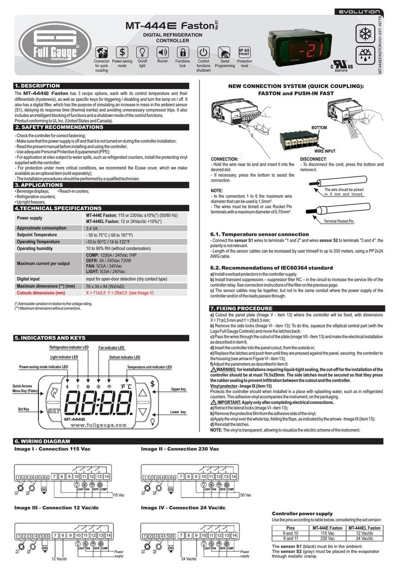
Full Gauge Faston MT-444e User manual

Full Gauge

Full Gauge Faston MT-444e User manual

Full Gauge TC-900 E User manual

Full Gauge

Full Gauge TC-900 E User manual

Full Gauge TC-900e 2HP User manual

Full Gauge

Full Gauge TC-900e 2HP User manual

Full Gauge TC-900RG2 slim User manual

Full Gauge

Full Gauge TC-900RG2 slim User manual

Full Gauge PCT-400R Plus User manual

Full Gauge

Full Gauge PCT-400R Plus User manual

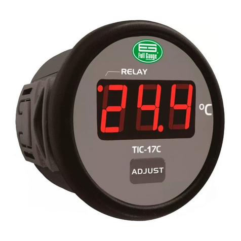
Full Gauge TIC-17 Series User manual

Full Gauge

Full Gauge TIC-17 Series User manual

Full Gauge EasyProg User manual

Full Gauge

Full Gauge EasyProg User manual

Full Gauge TIC-17 Series Manual

Full Gauge

Full Gauge TIC-17 Series Manual

Full Gauge TC-900EL Log User manual

Full Gauge

Full Gauge TC-900EL Log User manual

Full Gauge Microsol II E plus User manual

Full Gauge

Full Gauge Microsol II E plus User manual

Full Gauge TC-900Ri User manual

Full Gauge

Full Gauge TC-900Ri User manual

Full Gauge TC-970E+ECO Faston User manual

Full Gauge

Full Gauge TC-970E+ECO Faston User manual

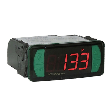
Full Gauge PCT-120E plus User manual

Full Gauge

Full Gauge PCT-120E plus User manual

Full Gauge MT-512Ri LOG User manual

Full Gauge

Full Gauge MT-512Ri LOG User manual

Full Gauge CONV 256 User manual

Full Gauge

Full Gauge CONV 256 User manual

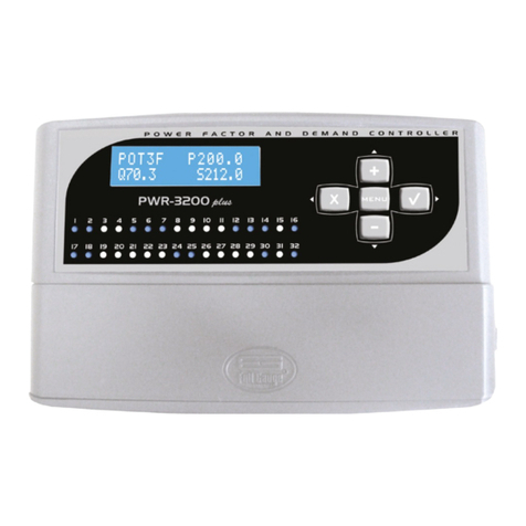
Full Gauge PWR-3200 plus User manual

Full Gauge

Full Gauge PWR-3200 plus User manual

Full Gauge MT-444 eXpress User manual

Full Gauge

Full Gauge MT-444 eXpress User manual

Full Gauge MT-514 E FASTON User manual

Full Gauge

Full Gauge MT-514 E FASTON User manual

Popular Controllers manuals by other brands

Steca Solarix 2401 manual

Steca

Steca Solarix 2401 manual

Newport i/8 quick start

Newport

Newport i/8 quick start

SMC Networks LEY series operating manual

SMC Networks

SMC Networks LEY series operating manual

Toho Electronics TTM-300 Series instruction manual

Toho Electronics

Toho Electronics TTM-300 Series instruction manual

Honeywell HA20 Technical manual

Honeywell

Honeywell HA20 Technical manual

MPE SC100 instruction manual

MPE

MPE SC100 instruction manual

JUMO TYA S202 operating manual

JUMO

JUMO TYA S202 operating manual

zeeltronic PDCI-NS1V user manual

zeeltronic

zeeltronic PDCI-NS1V user manual

Satel MICRA VERSA-MCU manual

Satel

Satel MICRA VERSA-MCU manual

PowerTech MP3741 user manual

PowerTech

PowerTech MP3741 user manual

HGM COMPUSHIFT Mini manual

HGM

HGM COMPUSHIFT Mini manual

Honeywell S4565 Series Production handbook

Honeywell

Honeywell S4565 Series Production handbook

Elsema Eclipse MCS Setup manual

Elsema

Elsema Eclipse MCS Setup manual

Linak TWINDRIVE TD1 Product data sheet

Linak

Linak TWINDRIVE TD1 Product data sheet

Tektronix 7S12 instruction manual

Tektronix

Tektronix 7S12 instruction manual

CD Automation REVO C 2PH 690V user manual

CD Automation

CD Automation REVO C 2PH 690V user manual

Reer MOSAIC Master M1 Installation and use manual

Reer

Reer MOSAIC Master M1 Installation and use manual

Samson 3374 Mounting and operating instructions

Samson

Samson 3374 Mounting and operating instructions

manuals.online logo
manuals.online logoBrands
  • About & Mission
  • Contact us
  • Privacy Policy
  • Terms and Conditions

Copyright 2025 Manuals.Online. All Rights Reserved.