ETAS ES4456.2 User manual

ES4456.2 Load Board for 8 RB CRI3-x Piezo Injectors
User’s Guide

2
Copyright
The data in this document may not be altered or amended without special noti-
fication from ETAS GmbH. ETAS GmbH undertakes no further obligation in rela-
tion to this document. The software described in it can only be used if the
customer is in possession of a general license agreement or single license. Using
and copying is only allowed in concurrence with the specifications stipulated in
the contract.
Under no circumstances may any part of this document be copied, reproduced,
transmitted, stored in a retrieval system or translated into another language
without the express written permission of ETAS GmbH.
© Copyright 2019 ETAS GmbH, Stuttgart
The names and designations used in this document are trademarks or brands
belonging to the respective owners.
V1.0.0 R03 EN - 10.2019

ES4456.2 Load Board for 8 RB CRI3-x Piezo Injectors - User’s Guide 3
Contents
ETAS Contents
1 Introduction . . . . . . . . . . . . . . . . . . . . . . . . . . . . . . . . . . . . . . . . . . . . . . . . . . . . . . 5
1.1 Applications and Features . . . . . . . . . . . . . . . . . . . . . . . . . . . . . . . . . . . . . . . 5
1.2 Basic Safety Instructions . . . . . . . . . . . . . . . . . . . . . . . . . . . . . . . . . . . . . . . . 8
1.2.1 Labeling of Safety Instructions . . . . . . . . . . . . . . . . . . . . . . . . . . . . . 8
1.2.2 General Safety Information . . . . . . . . . . . . . . . . . . . . . . . . . . . . . . . 8
1.2.3 Requirements for Users and Duties for Operators. . . . . . . . . . . . . . . 8
1.2.4 Intended Use . . . . . . . . . . . . . . . . . . . . . . . . . . . . . . . . . . . . . . . . . . 9
1.3 Identifications on the Product . . . . . . . . . . . . . . . . . . . . . . . . . . . . . . . . . . . 14
1.3.1 CE Mark . . . . . . . . . . . . . . . . . . . . . . . . . . . . . . . . . . . . . . . . . . . . 15
1.3.2 RoHS Conformity. . . . . . . . . . . . . . . . . . . . . . . . . . . . . . . . . . . . . . 15
1.3.3 P007 Identification in Accordance with ISO 7010:2011 . . . . . . . . . 15
1.4 Product Return and Recycling . . . . . . . . . . . . . . . . . . . . . . . . . . . . . . . . . . 16
1.5 Materials Subject to Declaration . . . . . . . . . . . . . . . . . . . . . . . . . . . . . . . . . 16
1.6 About this Manual . . . . . . . . . . . . . . . . . . . . . . . . . . . . . . . . . . . . . . . . . . . 17
1.6.1 Working with this Manual . . . . . . . . . . . . . . . . . . . . . . . . . . . . . . . 17
2 Hardware . . . . . . . . . . . . . . . . . . . . . . . . . . . . . . . . . . . . . . . . . . . . . . . . . . . . . . . 19
2.1 Connecting Loads and Measuring the Signals . . . . . . . . . . . . . . . . . . . . . . . 19
2.2 Overcurrent Protection of the Measure Outputs . . . . . . . . . . . . . . . . . . . . . 19
2.3 LED Display . . . . . . . . . . . . . . . . . . . . . . . . . . . . . . . . . . . . . . . . . . . . . . . . . 19
2.4 Acoustic Signals . . . . . . . . . . . . . . . . . . . . . . . . . . . . . . . . . . . . . . . . . . . . . 20
2.5 Calibration . . . . . . . . . . . . . . . . . . . . . . . . . . . . . . . . . . . . . . . . . . . . . . . . . 20
2.6 Settings in LABCAR-RTC . . . . . . . . . . . . . . . . . . . . . . . . . . . . . . . . . . . . . . . 20
3 Pin Assignment, Cables and Display Elements . . . . . . . . . . . . . . . . . . . . . . . . . . . . 23
3.1 “Load 0..7” Connector . . . . . . . . . . . . . . . . . . . . . . . . . . . . . . . . . . . . . . . . 23
3.2 Cables . . . . . . . . . . . . . . . . . . . . . . . . . . . . . . . . . . . . . . . . . . . . . . . . . . . . 23
3.2.1 “CBAV344.1-1” Cable . . . . . . . . . . . . . . . . . . . . . . . . . . . . . . . . . 24
3.2.2 “CBAV345.1-1” Cable . . . . . . . . . . . . . . . . . . . . . . . . . . . . . . . . . 25

ES4456.2 Load Board for 8 RB CRI3-x Piezo Injectors - User’s Guide4
Contents ETAS
3.3 LEDs for Status Display . . . . . . . . . . . . . . . . . . . . . . . . . . . . . . . . . . . . . . . . 27
4 Technical Data . . . . . . . . . . . . . . . . . . . . . . . . . . . . . . . . . . . . . . . . . . . . . . . . . . . 29
4.1 Standards Met . . . . . . . . . . . . . . . . . . . . . . . . . . . . . . . . . . . . . . . . . . . . . . 30
5 Ordering Data and Scope of Delivery. . . . . . . . . . . . . . . . . . . . . . . . . . . . . . . . . . . 31
6 ETAS Contact Addresses . . . . . . . . . . . . . . . . . . . . . . . . . . . . . . . . . . . . . . . . . . . . 33
Index . . . . . . . . . . . . . . . . . . . . . . . . . . . . . . . . . . . . . . . . . . . . . . . . . . . . . . . . . . 35

ES4456.2 Load Board for 8 RB CRI3-x Piezo Injectors - User’s Guide 5
ETAS Introduction
1 Introduction
This User’s Guide describes the ES4456.2 Load Board for 8 RB CRI3-x Piezo Injec-
tors. It consists of the following chapters:
1.1 Applications and Features
Applications
The ES4456.2 Load Board for 8 RB CRI3-x Piezo Injectors is a load simulation for
eight Piezo Injectors.
The ES4456.2 can be directly built into the ES4408.1 Load Chassis. If the
ES4456.2 is built into the ES5372.1-B Carrier Board, it can also be used in the
ES5300.1-A Housing or in the ES5300.1-B Housing.
For fast project change, an ES4408.1 Load Chassis is usually equipped with two
ES4450.2 Load Boards for 4 RB CRS Injectors (or two ES4451.3 Load Boards for
4 RB GDI Injectors) for simulating eight injectors with solenoid valves for Com-
mon Rail systems or gasoline direct injection and one ES4456.2 Load Board for 8
RB CRI3-x Piezo Injectors for simulating eight Piezo Injectors.
Fig. 1-1 ES4408.1 Load Chassis with ES4456.2 Load Board for 8 RB CRI3-x
Piezo Injectors (Slot 3)
ETAS
ES4451.3
Threshold high Load 0
Threshold low Load 0
Threshold high Load 1
Threshold low Load 1
Threshold high Load 2
Threshold low Load 2
Threshold high Load 3
Threshold low Load 3
Threshold
calibration
connection
!
Load0
Load1
Load2
Load3
ETAS
ES4451.3
Threshold high Load 0
Threshold low Load 0
Threshold high Load 1
Threshold low Load 1
Threshold high Load 2
Threshold low Load 2
Threshold high Load 3
Threshold low Load 3
Threshold
calibration
connection
!
Load0
Load1
Load2
Load3
ES4434.1
1
ETAS
2
34
56
78
910
11 12
13 14
15 16
17 18
19 20
21 22
23 24
ES4434.1
1
ETAS
2
34
56
78
910
11 12
13 14
15 16
17 18
19 20
21 22
23 24
ES4434.1
1
ETAS
2
34
56
78
910
11 12
13 14
15 16
17 18
19 20
21 22
23 24
ES4435.1
ETAS
ES4435.1
ETAS
+ 5 V
+ 3.3 V
- 12 V
+ 12 V
+ 24 V
ETAS
Load 0..3
ES4456.2
Load 4..7
Load 0..7

ES4456.2 Load Board for 8 RB CRI3-x Piezo Injectors - User’s Guide6
Introduction ETAS
Features
The ES4456.2 Load Board for 8 RB CRI3-x Piezo Injectors has the following fea-
tures:
• 3 U plug-in board (14 HP, 340 mm x 100 mm)
• Eight channels for load simulations to 16 A/250 V
• Eight galvanically isolated analog channels for voltage measuring
Fig. 1-2 shows the block diagram of the ES4456.2 Load Board for 8 RB CRI3-x
Piezo Injectors.
Fig. 1-2 Block Diagram of the ES4456.2 Load Board for 8 RB CRI3-x Piezo
Injectors
PLD
EEPROM
Load 1
DAC
V_Out Output
Protection
Load 8
DAC
V_Out Output
Protection
...

ES4456.2 Load Board for 8 RB CRI3-x Piezo Injectors - User’s Guide 7
ETAS Introduction
The following figure shows the front panel of the ES4456.2 Load Board for 8 RB
CRI3-x Piezo Injectors.
Fig. 1-3 Front Panel of the ES4456.2 Load Board for 8 RB CRI3-x Piezo Injec-
tors
The elements of the front panel are:
• The LEDs “Load n” that light up when the currents exceed the thresholds
set in the software
• The “Load 0..7” port to which the eight loads of the board can be con-
nected (e.g. to a LABCAR).
ETAS
Load 0..3
ES4456.2
Load 4..7
Load 0..7

ES4456.2 Load Board for 8 RB CRI3-x Piezo Injectors - User’s Guide8
Introduction ETAS
1.2 Basic Safety Instructions
Please adhere to the safety instructions in this manual to avoid injury to yourself.
1.2.1 Labeling of Safety Instructions
The safety instructions contained in this manual are shown with the standard
danger symbol shown below:
The following safety instructions are used. They provide extremely important
information. Please read this information carefully.
1.2.2 General Safety Information
Observe the following safety notices to avoid health issues or damage to the
device.
ETAS GmbH does not assume any liability for damages resulting from improper
handling, unintended use or non-observance of the safety precautions.
1.2.3 Requirements for Users and Duties for Operators
The product may be assembled, operated and maintained only if you have the
necessary qualification and experience for this product. Improper use or use by a
user without sufficient qualification can lead to damages or injuries to one's
health or damages to property.
The system integrator is responsible for the safety of systems that use the prod-
uct.
General Safety at Work
Follow the existing regulations for work safety and accident prevention. All appli-
cable regulations and laws regarding operation must be strictly adhered to when
using this product.
CAUTION!
indicates a low-risk danger which could result in minor or less serious
injury or damage if not avoided.
WARNING!
indicates a possible medium-risk danger which could lead to serious
or even fatal injuries if not avoided.
DANGER!
indicates a high-risk, immediate danger which could lead to serious
or even fatal injuries if not avoided.
Note
The User's Guide and the Product Safety Advice must be read carefully prior to
the startup of the product!

ES4456.2 Load Board for 8 RB CRI3-x Piezo Injectors - User’s Guide 9
ETAS Introduction
1.2.4 Intended Use
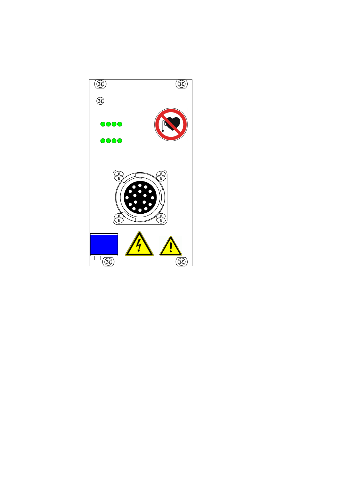
The ES4456.2 Load Board for 8 RB CRI3-x Piezo Injectors is for load emulation of
eight piezo injectors.
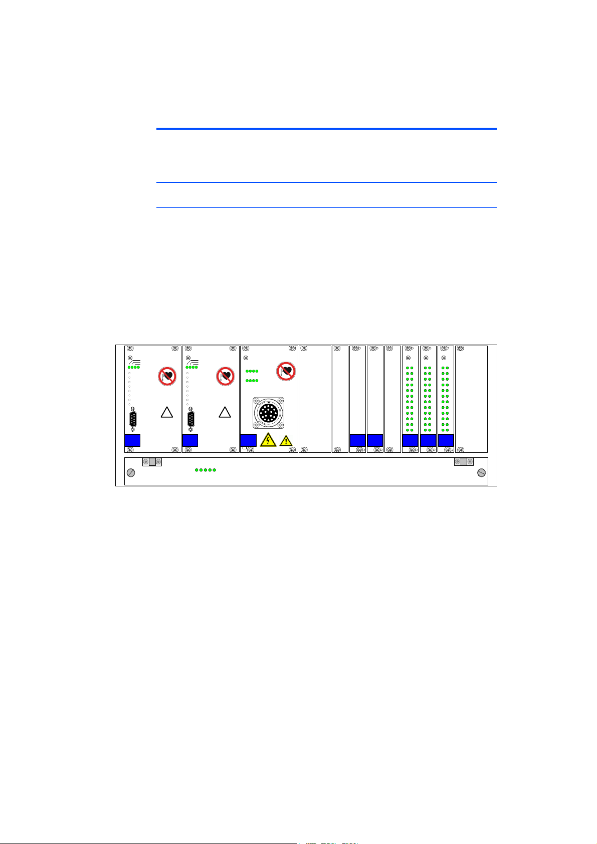
The ES4456.2 is a plug-in board for the ES4408.1 Load Chassis. When built into
the ES5372.1-B, it can also be used in the ES5300.1-A Housing and the
ES5300.1-B Housing.
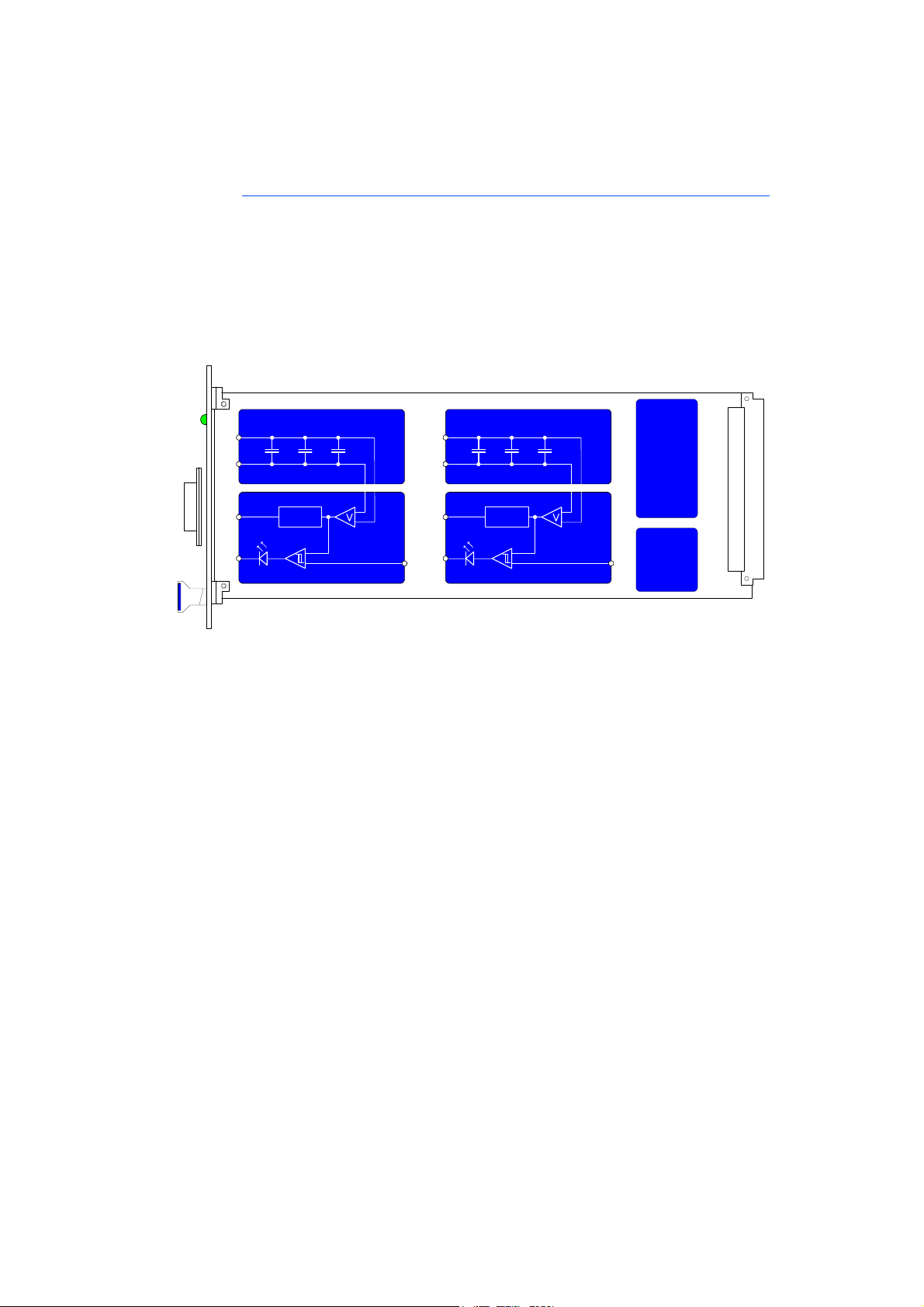
The ES4456.2 consists of the following:
• Load emulation for 8 RB CRI13-x piezo injectors with connections to ECU
output stages
• Digital and analog output interfaces for the ES4408.1 or ES5300.1-A-
based hardware-in-the-loop system or for connecting oscilloscopes or
other measurement devices
• SPI interface to the ES4408.1 Load Chassis, the ES5300.1-A Housing or
ES5300.1-B Housing
The ES4456.2 may be installed and operated only in the ES4408.1 Load Chassis,
the ES5300.1-A Housing or in the ES5300.1-B Housing.
The intended use of the ES4456.2 in an ES4408.1 Load Chassis, an ES5300.1-A
Housing or ES5300.1-B Housing is:
• Use as a component in industrial lab facilities or at industrial workplaces
• Use as hardware interface for ECUs in a hardware-in-the-loop test system
• Use in conjunction with ETAS software that supports the ES4408.1 Load
Chassis, th ES5300.1-A Housing and the ES5300.1-B Housing
• Use as interface in cooperation with software programs that operate the
standardized, documented and open APIs of ETAS software products
The ES4456.2 is not intended for the following:
• Use within a vehicle on the road.
• Use as part of a life support system.
• Use as part of a medical application
• In applications where misuse can lead to injuries or damages.
• Use in environments in which conditions prevail that fall outside the spec-
ified ranges (see "Environmental Conditions" on page 29).
• Use with signal conditioning that falls outside the specified ranges (see
voltages, currents and power consumption in the chapter "Technical
Data" on page 29)
Requirements for the Technical State of the Product
The product is designed in accordance with state-of-the-art technology and rec-
ognized safety rules. The product may be operated only in a technically flawless
condition and according to the intended purpose and with regard to safety and
dangers as stated in the respective product documentation. If the product is not
used according to its intended purpose, the protection of the product may be
impaired.
Requirements for Operation
The following requirements are necessary for safe operation:

ES4456.2 Load Board for 8 RB CRI3-x Piezo Injectors - User’s Guide10
Introduction ETAS
• Use the product only according to the specifications in the corresponding
User's Guide. With any deviating operation, the product safety is no lon-
ger ensured.
• Do not use the product in a wet or damp environment.
• Do not use the product in potentially explosive atmospheres.
Electrical Safety and Power Supply
Observe the regulations applicable at the operating location concerning electrical
safety as well as the laws and regulations concerning work safety!
DANGER!
Risk of electric shock!
At the plug Load 0...7 high voltages may still be present even after
disconnecting the counter plug.
After disconnecting the cable, wait one minute before touching the
connections or the circuit board. Parallel to the capacitors are resis-
tors that allow a safe discharging.
Nonobservance may lead to fatal injury or death.
WARNING!
Danger of high voltages!
The components, plug connectors, conductor paths of the ES4456.2
may have dangerous voltages. These voltages can also be present
when the ES4456.2 is not installed in the ES4408.1 Load Chassis, the
ES5300.1-A Housing or in the ES5300.1-B Housing or if the ES4408.1
Load Chassis, the ES5300.1-A Housing and the ES5300.1-B Housing
are switched off.
Ensure that the ES4456.2 is protected against touching it during
operation. Switch off the ES4408.1 Load Chassis, the ES5300.1-A
Housing or the ES5300.1-B Housing and pull the power plug. Wait at
least three minutes before removing the ES4456.2.
Nonobservance may lead to fatal injury or death.
WARNING!
Danger trough electromagnetic radiation!
The ES4456.2 and loads connected to it, can emit electromagnetic
radiation during operation which can cause interference with the
operation or damage pacemakers or implanted defibrillators.
The ES4456.2 may be operated only in areas where persons with
pacemakers are prohibited from entering. At the entrances to these
areas, the P007 identification, "No access for persons with pacemak-
ers or implanted defibrillators" in accordance with ISO 7010:2011
"Registered Safety Signs", must be attached and clearly legible.
Failure to observe it can lead to health hazards and even death for
persons with pacemakers and implanted defibrillators.

ES4456.2 Load Board for 8 RB CRI3-x Piezo Injectors - User’s Guide 11
ETAS Introduction
Power Supply
The product is powered by the ES4408.1 Load Chassis. If the ES4456.2 is built
into the ES5300.1-A Housing or the ES5300.1-B Housing, the ES4456.2 is pow-
ered via the PCIe Backplane Connector of the ES5300.1-A Housing or ES5300.1-
B Housing.
Insulation Requirements for Lab Power Supplies to Circuits Connected to the HIL
System:
• The power supply to live circuitry must be safely isolated from the supply
voltage. For example, use a car battery or a suitable lab power supply.
• Only use lab power supplies with dual protection for the supply network
(with double/reinforced insulation (DI/RI)). This requirement is met by lab
power supplies that comply with IEC/EN 60950 or IEC/EN 61010.
• The lab power supply must be approved for use at a height of 2000 m and
in ambient temperatures of up to 40 °C.
De-energizing a Plug-in Board
Switch off the ES4408.1 Load Chassis, the ES5300.1-A Housing or the ES5300.1-
B Housing and external power supplies, and unplug the power plug and other
connectors attached to the plug-in board. Wait at least three minutes before
removing the plug-in board.
Approved Cables
The signal lines must not exceed a maximum length of 3 m.
WARNING!
Fire hazard!
Use only fuses that meet the specification in the User’s Guide of the
product! Never bridge defective fuses!
Failure to observe the fuse specification can lead to excess currents,
short circuits and fires.
WARNING!
Fire hazard!
Use only approved cables for creating cable assemblies (e.g. for con-
necting the ECU and external loads). The cables used must be suitable
particularly for occurring currents, voltages and temperatures and
flame-retardant in accordance with one of the following standards
IEC 60332-1-2, IEC 60332-2-2, UL 2556/UL1581VW-1!

ES4456.2 Load Board for 8 RB CRI3-x Piezo Injectors - User’s Guide12
Introduction ETAS
Requirements for the Installation Location
Requirements for Ventilation
Transport and Installation
To avoid damages to the hardware from electrostatic discharge, please observe
the following precautionary measures:
WARNING!
This is class A equipment. This equipment can cause radio interfer-
ence in residential areas. Should that be the case, the operator may
be requested to institute reasonable measures.
CAUTION!
The air circulation inside the ES4408.1 Load Chassis, the ES5300.1-A
housing and the ES5300.1-B housing can be ensured only if all free
slots are covered with front plates. Otherwise, it may lead to overtem-
peratures and trip the overtemperature protection of the ES5300.1-A
or the ES5300.1-B. For this reason, install front plates in all free slots!
CAUTION!
Some components of the ES4456.2 can be damaged or destroyed by
electrostatic discharges. Leave the plug-in cards in their transport
packaging until their installation.
Remove, configure and install the ES4456.2 only at a workplace
secured against static discharges.
CAUTION!
In order to prevent damage to the plug-in boards and the LABCAR
housing, and thereby also avoid damage to property or health,
observe the installation instructions and information contained in the
relevant User's Guides.
WARNING!
Risk of electric shock, fire hazard!
For safety reasons, the assembly of the ES5372.1-B and ES4456.2
may be performed only at ETAS. If you purchased the two products
individually, please contact your ETAS contact person so that the
ES5372.1-B and the ES4456.2 can be returned to ETAS for assembly.
Failure to observe it can lead to an incorrect pin assignment, damage
to the board of the ES4456.2 or short circuits. This causes a risk of
electric shock from high voltages and of fires.

ES4456.2 Load Board for 8 RB CRI3-x Piezo Injectors - User’s Guide 13
ETAS Introduction
Connecting/Disconnecting Devices
To avoid injuries and hardware damages, observe the following precautionary
measures:
• Do not apply any voltages to the connections of the ES4456.2 that do not
correspond to the specifications of the respective connection.
• Do not connect or disconnect any devices while the ES4408.1 Load Chas-
sis, the ES5300.1-A Housing or ES5300.1-B Housing or external devices
are switched on. First, switch off the ES4408.1 Load Chassis, the
ES5300.1-A Housing and the ES5300.1-B Housing by shutting down the
real-time PC and by activating the On/Off switch at the rear and unplug
the power cable.
• When plugging in connectors, ensure that they are inserted straight and
no pins are bent.
• When crimping the plug contacts of Positronic, use only the crimping tool
intended for this purpose.
Maintenance
The product does not require maintenance.
Repairs
If an ETAS hardware product needs to be repaired, return the product to ETAS.
Cleaning
The product is not expected to require cleaning.
CAUTION!
If cards (e.g. for startup or calibration) are unlocked but not com-
pletely removed from the housing, they must be pulled out far
enough that the distance between the respective card and the back-
plane of the housing is at least 1 cm. Otherwise, contacts may be
established between the cards and lead to their destruction.

ES4456.2 Load Board for 8 RB CRI3-x Piezo Injectors - User’s Guide14
Introduction ETAS
1.3 Identifications on the Product
The following Symbols are Used for Product Labeling:
Observe the information in the chapter "Technical Data" on page 29.
Symbol Description
The User's Guide must be read prior to the startup of the
product
W012 identification in accordance with DIN EN ISO 7010:
"Warning about electrical voltage"
Marking for CE conformity
(see "CE Mark" on page 15)
Marking for China RoHS
(see "RoHS Conformity" on page 15)
Marking for conformity with WEEE directive
(see "Product Return and Recycling" on page 16)
P007 identification in accordance with ISO 7010:2011: "No
access for persons with pacemakers and implanted defibrilla-
tors".
"Operational malfunction or damage to pacemakers and
implanted defibrillators".

ES4456.2 Load Board for 8 RB CRI3-x Piezo Injectors - User’s Guide 15
ETAS Introduction
1.3.1 CE Mark
With the CE mark attached to the product or its packaging, ETAS confirms that
the product corresponds to the product-specific, applicable European Directives.
The CE Declaration of Conformity for the product is available upon request.
1.3.2 RoHS Conformity
European Union
The EU directive 2011/65/EU limits the use of certain dangerous materials for
electric and electronic devices (RoHS conformity).
ETAS confirms that the product meets this directive applicable in the European
Union.
China
With the China RoHS identification attached to the product or its packaging,
ETAS confirms that the product meets the guidelines of the "China RoHS" (Man-
agement Methods for Controlling Pollution Caused by Electronic Information
Products Regulation) applicable in the People's Republic of China.
1.3.3 P007 Identification in Accordance with ISO 7010:2011
Under consideration of the standard ISO 7010:2011, the product is labeled with
the symbol "No access for persons with pacemakers or implanted defibrillators".
The ES4456.2 may be operated only in areas where persons with pacemakers are
prohibited from entering. The user is obligated to attach a clearly legible P007
identification, "No access for persons with pacemakers or implanted defibrilla-
tors" in accordance with ISO 7010:2011 "Registered Safety Signs", at the
entrances to these areas.

ES4456.2 Load Board for 8 RB CRI3-x Piezo Injectors - User’s Guide16
Introduction ETAS
1.4 Product Return and Recycling
The European Union (EU) released the Directive for Waste Electrical and Elec-
tronic Equipment - WEEE to ensure the setup of systems for collecting, treating
and recycling electronic waste in all countries of the EU.
This ensures that the devices are recycled in a resource-friendly way that does not
represent any risk to personal health and the environment.
Fig. 1-4 WEEE symbol
The WEEE symbol on the product or its packaging identifies that the product may
not be disposed of together with the remaining trash.
The user is obligated to separately collect old devices and provide them to the
WEEE return system for recycling.
The WEEE Directive applies to all ETAS devices, but not to external cables or bat-
teries.
Additional information about the recycling program of ETAS GmbH is available
from the ETAS sales and service locations (see "ETAS Contact Addresses"
on page 43).
1.5 Materials Subject to Declaration
Some products from ETAS GmbH (e.g. modules, boards, cables) use components
with materials that are subject to declaration in accordance with the REACH reg-
ulation (EC) no.1907/2006.
Detailed information is located in the ETAS download center in the customer
information "REACH Declaration" < www.etas.com/Reach >. This information is
continuously being updated.

ES4456.2 Load Board for 8 RB CRI3-x Piezo Injectors - User’s Guide 17
ETAS Introduction
1.6 About this Manual
This manual consists of the following chapters:
• "Introduction" on page 5
This chapter
• "Hardware" on page 19
• "Pin Assignment, Cables and Display Elements" on page 23
• "Technical Data" on page 29
• "Ordering Data and Scope of Delivery" on page 31
1.6.1 Working with this Manual
Presentation of Information
All activities to be performed by the user are presented in a "Use Case" format.
That is, the goal to be accomplished is briefly defined in the heading, and the
respective steps required for reaching this goal are then presented in a list. The
presentation looks as follows:
Target Definition
Any advance information...
1. Step 1
Any explanation for step 1...
2. Step 2
Any explanation for step 2...
Any concluding comments...
Specific example:
Creating a New File
Before creating a new file, no other file may be open.
1. Select File → New.
The "Create File" dialog box appears.
2. Enter the name of the new file in the “File name”
field.
The file name may not have more than 8 characters.
3. Click on OK.
The new file is being created and saved under the name you specified. You can
now work with the file.

ES4456.2 Load Board for 8 RB CRI3-x Piezo Injectors - User’s Guide18
Introduction ETAS
Typographical Conventions
The following typographical conventions are used:
Important notes for the user are presented as follows:
Select File →Open. Menu commands are displayed in bold/
blue.
Click on OK. Buttons are displayed in bold/blue.
Press <ENTER>. Key commands are printed in small capi-
tals enclosed in angle brackets.
The "Open file" dialog window
appears.
Names of program windows, dialog win-
dows, fields and similar are given in quota-
tion marks.
Select the setup.exe file. Text in selection lists, program code, as
well as path and file names are displayed
using the Courier font.
A conversion between the logical
and arithmetic data types is not
possible.
Content-based highlights and newly intro-
duced terms are placed in italics.
Note
Important note for the user.

ES4456.2 Load Board for 8 RB CRI3-x Piezo Injectors - User’s Guide 19
ETAS Hardware
2 Hardware
This chapter describes the individual function units of the ES4456.2 Load Board
for 8 RB CRI3-x Piezo Injectors in more detail.
These are:
• "Connecting Loads and Measuring the Signals" on page 19
• "Overcurrent Protection of the Measure Outputs" on page 19
• "LED Display" on page 19
• "Acoustic Signals" on page 20
• "Calibration" on page 20
• "Settings in LABCAR-RTC" on page 20
2.1 Connecting Loads and Measuring the Signals
The ES4456.2 Load Board for 8 RB CRI3-x Piezo Injectors can be used in slot 1, 2
or 3 in an ES4408.1 Load Chassis. The loads are connected at the front panel
connector “Load 0...7” of the ES4456.2 - the measure signals are available at
connectors on the back of the ES4408.1 Load Chassis.
For details of the pin assignment of the front panel connector “Load 0...7” refer
to section "“Load 0..7” Connector" on page 23 – the pin assignment of the
measure connectors is described in the ES4408.1 Load Chassis manual.
Special cables are available for connecting loads and measure signals with a PT-
LABCAR (see "“CBAV344.1-1” Cable" on page 24 and "“CBAV345.1-1”
Cable" on page 25).
2.2 Overcurrent Protection of the Measure Outputs
The outputs of the ES4456.2 Load Board for 8 RB CRI3-x Piezo Injectors are pro-
tected against shorts to +UBatt and against ±60 V.
2.3 LED Display
The LED display on the front panel (see "LEDs for Status Display" on page 27)
shows when a specific voltage value between 0 and 250 V has been reached – if
the voltage at a load is over this value, the relevant LED lights up.
The thresholds are set in the software; this is described in the section "To set
thresholds for LEDs" on page 20.
Board in Slot Measure Signals to
1 Meas 8-2
2 Meas 8-1
3 Meas 7
Note
The “CBAV345.1-1” cable must be used if the measure signals are from an
ES4456.2 Load Board for 8 RB CRI3-x Piezo Injectors. It is not possible to use
one of the three DSUB9 connectors of the CBAV343.1-1 cable which are
intended for slots with an ES4450.2 Load Board for 4 RB CRS Injectors or an
ES4451.3 Load Board for 4 RB GDI Injectors.

ES4456.2 Load Board for 8 RB CRI3-x Piezo Injectors - User’s Guide20
Hardware ETAS
2.4 Acoustic Signals
An acoustic signal can be emitted when the above-mentioned thresholds have
been attained. The section "To set the beeper" on page 21 describes how to
enable/disable this function.
2.5 Calibration
ETAS provides a calibration service for correcting any voltage converter offsets.
The order data is as follows:
2.6 Settings in LABCAR-RTC
The software settings for the ES4456.2 Load Board for 8 RB CRI3-x Piezo Injec-
tors are described below.
To set thresholds for LEDs
1. To configure the thresholds for the optical (via LEDs)
and acoustic signals, select the “Signals” tab.
2. Enter a value (for the relevant channel) for “LED
Switching Level [V]”.
3. Click Accept.
The settings are accepted.
For more detailed information on LABCAR-RTC, refer to the LABCAR-RTC User’s
Guide.
Order Name Short Name Order Number
Calibration Service for ES4456 K_ES4456 F-00K-106-542
Table of contents
Other ETAS Motherboard manuals