ETLOC ETLOC-50 SECURITY User manual


Installation manual (ver. 2/2018) ETLOC-50 SECURITY
2
Table of contents
I. SIM card preparation 3
II. Installation into a vehicle 3
1. Placement of the unit 3
2. Connecting the cable harness 4
2.1. Input IGNITION 6
2.2. Input ALARM 1 6
2.3. Input ALARM 2 6
2.4. Output (switching relay) 6
2.5. Output STOP 6
3. Mounting the GPS antenna 7
4. Activation of the unit 8
5. Connecting the backup battery 9
6. Mounting the individual components 9
Installation manual (ver. 2/2018) ETLOC-50 SECURITY
3
I. SIM card preparation
Make sure the new SIM card is active and disable its PIN code protection (the PIN can be
disabled via mobile phone). You can use either a prepaid or tariff SIM card. The ETLOC unit
communicates via mobile data and optionally via SMS commands –please pay attention to
the prices for these services during the selection of your provider.
Activate the SIM card according the service provider instructions. It is necessary to disable
the SIM card PIN code protection. Insert the activated SIM card into the micro SIM card
holder . Pay attention to the correct SIM card orientation .
Note:
We recommend to activate roaming on the SIM card.
II. Installation into the vehicle
1. Placement of the unit
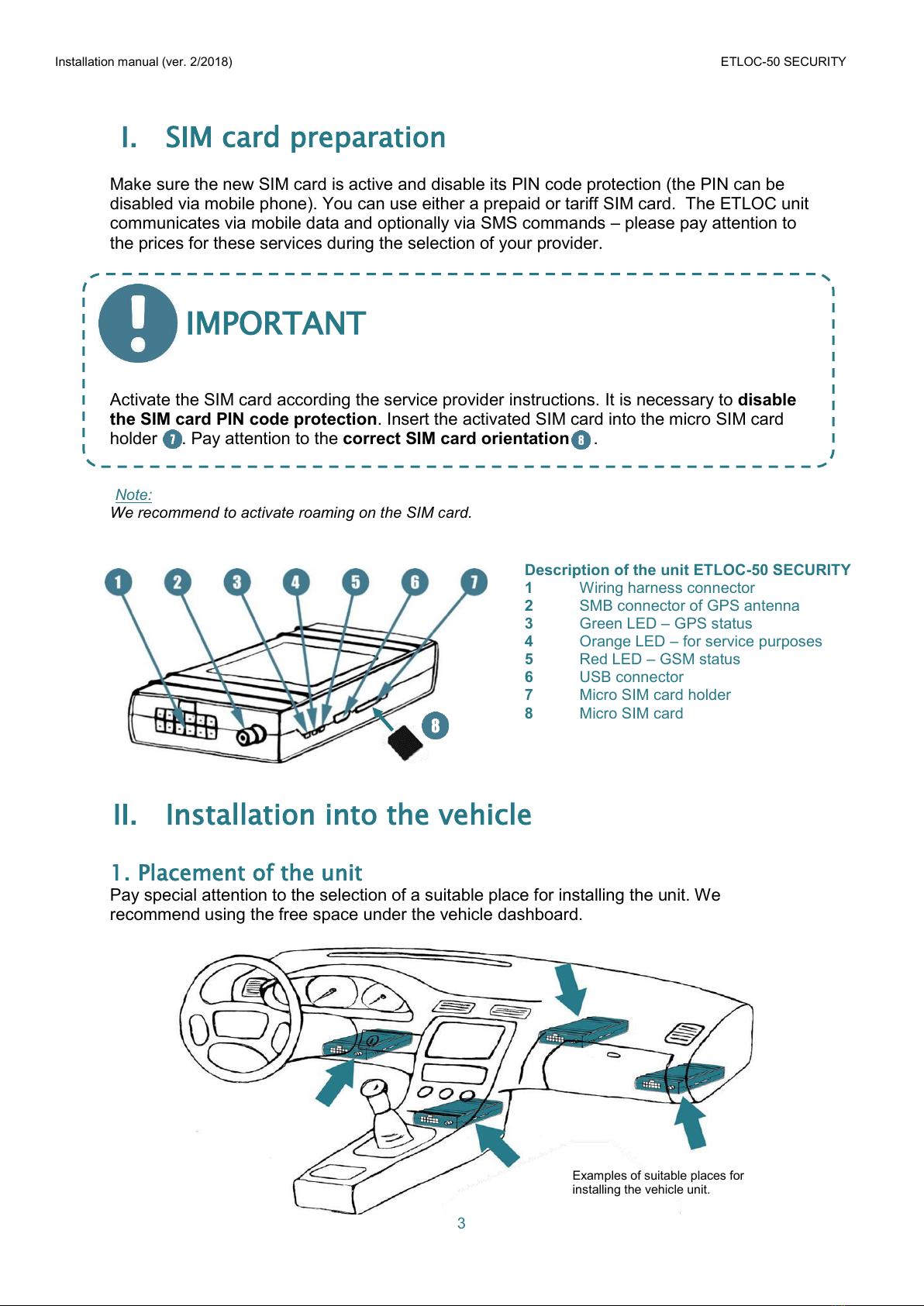
Pay special attention to the selection of a suitable place for installing the unit. We
recommend using the free space under the vehicle dashboard.
Description of the unit ETLOC-50 SECURITY
1 Wiring harness connector
2 SMB connector of GPS antenna
3 Green LED –GPS status
4 Orange LED –for service purposes
5 Red LED –GSM status
6 USB connector
7 Micro SIM card holder
8 Micro SIM card
IMPORTANT
Examples of suitable places for
installing the vehicle unit.

Installation manual (ver. 2/2018) ETLOC-50 SECURITY
4
The vehicle unit must not be placed in close proximity to solid metal structures (the vehicle
unit has an integrated GSM antenna) or in close proximity to other devices with increased
electromagnetic radiation (e.g. control units, electric motors, power relays, servo-drives etc.).
2. Connecting the cable harness
While connecting to the vehicle wiring, the wiring harness must be disconnected from the
vehicle unit.
Basic installation is done via three wires (black, red and yellow).
The remaining wires are used for specific features of the vehicle unit.
The wiring diagram of the
ETLOC-50 SECURITY unit
IMPORTANT

Installation manual (ver. 2/2018) ETLOC-50 SECURITY
5
The vehicle unit has to be connected via the red wire to a constant power supply without
current limit. Protect this connection with a 5 A fuse.
Grounding (black wire) must be done in the shortest possible distance from the car battery's
negative pole.
When the engine is running there must always be +12/24 volts on the IGNITION input
(yellow wire).
The individual wires of the wiring harness must be shortened to the absolute necessary
length. Cut the unused wires at the connector and insulate their ends.
Description of the vehicle unit ETLOC-50 SECURITY connector
Pin 1 2 x black a) vehicle GND b) backup accumulator GND
Pin 2 Yellow IGNITION input (activation +12/24 V)
Pin 3 White-green Not connected
Pin 4 White-black STOP output (activation GND)
Pin 5 Blue Switching relay –contact close (NC)
Pin 6 Brown Switching relay –common contact (COM)
Pin 7 Red Main power supply +12/24 V
Pin 8 Purple Not connected
Pin 9 White Input ALARM 2 (activation GND)
Pin 10 Orange Input ALARM 1 (activation +12/24 V)
Pin 11 White-red + 6 V backup accumulator
Pin 12 Green Switching relay –contact open (NO)
IMPORTANT
1
2
3
4
5
6
7
8
9
10
11
12
Overview of the vehicle unit’s connector

Installation manual (ver. 2/2018) ETLOC-50 SECURITY
6
2.1. IGNITION Input (connection of this input is compulsory)
This input is used for monitoring the condition of the vehicle's ignition.
With the ignition ON (vehicle engine running) there must always be a voltage of +12/24 V
on this input. The IGNITION input can be connected to any circuit in the vehicle, which is
active only when the engine is running.
2.2. Input ALARM 1
Input ALARM 1 is used as an independent information input which monitors the state or
activity of a particular device within the vehicle (e.g. external alarm activation, SOS button
activation, opening the lid of a tank, opening the cargo space, alcohol tester activation etc.).
Orange wire - activation of the input is done by a signal +12/24 V with a length of more than
0.8 s
2.3. Input ALARM 2
Input ALARM 2 is used as an independent information input which monitors the state or
activity of a particular device within the vehicle (e.g. external alarm activation, SOS button
activation, opening the lid of a tank, opening the cargo space, alcohol tester activation etc.).
White wire - activation of the input is done by grounding (GND) with a signal length of more
than 0.8 s
2.4. Output (switching relay)
The relay is used for example for controlling external heating, sirens, warning lights etc. with
a maximum load 5 A / 12 VDC (2,5 A / 24 VDC).
Note:
If you would like to control devices with a higher current load, use an auxiliary relay which has the
appropriate technical parameters.
2.5. Output STOP
Output STOP is an independent output specifically designed to safely stop the vehicle. The
output can only be activated when the vehicle stops - reduces speed to 0 km/h (e.g. at a
junction).
White-black wire - the output in a form of an open collector
(max output load 350 mA / 36 V).
Note:
With the STOP output an external relay can be controlled,
performing an appropriate action within the vehicle (e.g.
interrupting fuel injection pump power supply). In all cases,
the relay used MUST have diode protection.
IMPORTANT
Connection of an external relay with
diode protection to the STOP output.
Installation manual (ver. 2/2018) ETLOC-50 SECURITY
7
3. Mounting the GPS antenna
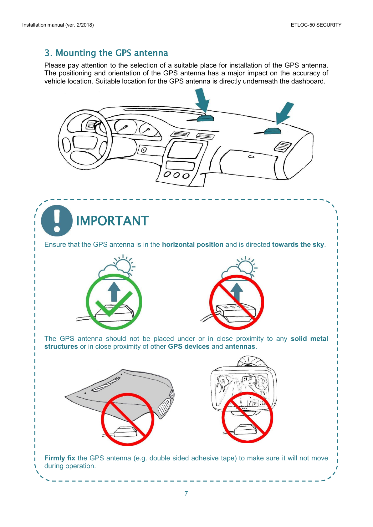
Please pay attention to the selection of a suitable place for installation of the GPS antenna.
The positioning and orientation of the GPS antenna has a major impact on the accuracy of
vehicle location. Suitable location for the GPS antenna is directly underneath the dashboard.
Ensure that the GPS antenna is in the horizontal position and is directed towards the sky.
The GPS antenna should not be placed under or in close proximity to any solid metal
structures or in close proximity of other GPS devices and antennas.
Firmly fix the GPS antenna (e.g. double sided adhesive tape) to make sure it will not move
during operation.
IMPORTANT

Installation manual (ver. 2/2018) ETLOC-50 SECURITY
8
Note:
If the vehicle is equipped with a metallized windshield, it is necessary to place the GPS antenna, for
example, into the side mirror, front plastic bumper or other location where its view to the sky won't be
shielded. A heated windshield is not a problem for GPS signal reception.
4. Activation of the unit
a) Attach the GPS antenna's SMB connector and wiring
harness connector to the vehicle unit (after attaching
the cable harness, the vehicle unit is not yet
activated - it is still switched off).
b) Start the vehicle and wait for approx. 2 minutes
(during this time the unit initializes). The LED lights on
the vehicle unit indicate its current state.
c) Send an SMS with the command STATE from your
mobile phone to the telephone number of the vehicle
unit. You will receive an SMS reply with information
about the installed unit’s current state.
1. IMEI –the unique identification
number of the vehicle unit
2. Inputs states IGNITION / ALARM
1 / ALARM 2
3. Switching relay state
4. STOP function state
Function STOP activation / Execution of STOP output
5. Vehicle battery voltage
6. Backup battery voltage
7. Charging of the backup battery
8. GSM signal power
9. GPRS state
Data transmission frequency / Data network connection
10. GPS module state
GPS module turned OFF/ON / Current position unknown/known
/ Number of visible satellites
d) Turn off the vehicle’s ignition and resend the SMS with the STATE command. In the reply
SMS, check that the IGNITION input is not active (INPUTS 0/0/0).
After turning the vehicle’s ignition off, wait for approx. 5 minutes and check if the vehicle
unit is still being powered (red LED must be flashing). With this procedure you will verify that
the circuit chosen for supplying power to the vehicle unit is not time-restricted and does not
cause the unit to switch off. NOTE: in order to perform this test correctly, the backup
battery has to be disconnected during the test.
IMPORTANT
STATE:
IMEI 866104028872547
INPUTS 1/0/0
SWITCH 0
STOP 1/0
CBAT 12,6V
BBAT 6,4V
CHARGE 0
GSM 28
GPRS I60s/1
GPS 1/1/5
Note: 0 –no/off, 1 –yes/on
state
LED is f lashing 1 x
per second
The unit is connecting to
GSM netw ork
LED is f lashing 1 x
per 3 seconds
The unit is connected to
GSM netw ork
LED is f lashing 3 x
per second
The device is connected to
GSM and GPRS
LED is not flashing The unit is sw itched off
LED is flashing 1 x
per second
The unit is trying to receive
GPS data
LED is flashing 1 x
per 3 seconds
The unit is receiving actual
GPS data
LED is not flashing GPS module is sw itched off
Gre e n LED – indicate s GPS status
Red LED – indicate s GSM status

Installation manual (ver. 2/2018) ETLOC-50 SECURITY
9
5. Connecting the backup battery (optional accessory)
The backup battery allows location of the vehicle even when the car battery is disconnected.
As a backup battery, please use only valve regulated lead acid batteries 6 V / 1,3 Ah.
The backup battery is connected through the wiring harness - black (-12 V) and red-white
(+12 V) wires equipped with FASTON connectors.
Note:
While the engine is running, the backup battery is being automatically recharged.
The lifespan of the backup battery is 3 years. After this period it should be replaced.
6. Mounting the individual components
Firmly fix the vehicle unit, backup battery and wiring harness in the designated place under
the dashboard. Mount the devices use double-sided adhesive tape and plastic cable ties.

Table of contents
Other ETLOC Car Alarm manuals


Popular Car Alarm manuals by other brands


Ultra Start
Ultra Start 650 Series owner's manual

Audiovox
Audiovox Prestige Platinum+ APS-511C owner's manual

Sparkrite
Sparkrite SRA8 Guide

Federal Signal Corporation
Federal Signal Corporation Pathfinder Siren Series Installation and maintenance manual

Falcon
Falcon Predator XL3 Installer manual

Audiovox
Audiovox Auto Security XR91 Programming guide


