Europa Aircraft Rotax 914 User manual

Europa XS
Rotax 914 Installation Manual
Europa XS Rotax 914 Engine Manual Issue 7 October 2004

Index of Chapters
Chapter Description
1 Engine installation
2 Engine controls
3 Oil tank
4 Cooling duct and coolers
5 Fuel system
6 Engine cowlings
7 Access doors
8 Propeller and spinner
9 Commissioning the engine
Annex A Final inspection checklist
September 2002 Issue 5 Europa XS Rotax 914 Engine Manual

1. Engine installation
Preparation
Before starting work on the engine installation read this manual and the Rotax 914 installation
manual. There are some delicate parts attached to the engine, notably the ignition triggers, which
require care in handling. Instead of installing the engine mounting to the aircraft, then trying to
positionaheavyengineontoit, theenginemountingshouldbeattachedtotheenginefirst. This may
have already been done at the Rotax factory.
The exhaust silencer has a slotted outlet stub and requires the tailpipe EX08 to be added to it. The
tailpipeisdesignedtobeclampedinposition. Seefigure1. Althoughthetailpipecouldbeweldedto
the silencer, for tri-gear operators this is not recommended as it is often better to remove the tailpipe
before fitting or removing the lower cowlings, as otherwise the presence of the nose gear can make
life difficult.
Engine mount fitting
There are two mounting frames associated with fitting the engine to the undercarriage frame: the
engine itself is already fitted to a ring mount which is a Rotax component, and that is fitted to the
Europa engine mount, which in turn is fitted to the undercarriage mount.
Page 1 - 1
Europa XS Rotax 914 Engine Manual Issue 6 September 2003
Fig 1. Exhaust tailpipe.

Fit the engine mounting frame to the Rotax ring mount using M10 x 110 bolts and M10 Binx nuts.
The upper bolts and the lower port bolt should be fitted with the bolt heads aft, and the lower
starboard bolt with the head forward. The excess length of the bolts will need to be cut off, leaving a
minimum of two threads emerging from the end of the nut. It will be necessary to chamfer the lower
starboard bolt’s head as shown in figure 2.
Engine installation
Mount the engine to the landing gear frame using the rubber mountings. See figure 2
Tochecktheorientationoftheengine,setthefuselagelevelusingtheportdoorsillasthereferenceas
usual. Check that the propeller flange is truly vertical.
The engine mounting frame has been designed with the engine offset to starboard by 1.5° To check
that this offset is correct clamp a straight edge to the propeller flange horizontally and mark a point
51cm(20")eachsideoftheenginecentreline.Measurethedistancefromthesepoints,paralleltothe
aircraft centre line, to the firewall. The difference between the two readings should be 26 mm
(1-1/16"). If any correction is found necessary, shim between the landing gear frame and the
appropriate cup washer using AN960-516L washers. In order to ensure that the split pin is correctly
positionedrelativetothecastellatednutitwillbenecessarytousea totalofatleast4washersoneach
bolt. Any washers that are not needed to act as positioning shims should be placed immediately
under the nut. Make a note of where and how many shim washers are used for later reference.
Note: The 4 AN5-41 mounting bolts must be tightened fully to compress the rubber anti-vibration
mounts (MT04) onto the steel spacers (MT03).
Caution:It should be noted that before the two ignition leads which come from the ignition box are
earthed, the ignition is ”live”. Even though the engine speed must be at least 1200 rpm for the
ignition to fire, it would be a sensible precaution to fit the magneto switches before further work is
carried out on the engine, or at least temporary earth leads connecting the ignition wires to the
engine casing.
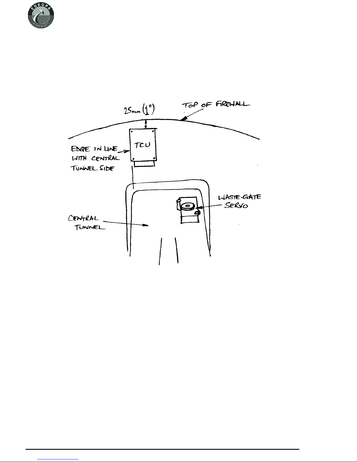
Wastegate control
The turbocharger wastegate is controlled by the TCU and operated by the servo motor unit. These
two items have to be positioned away from sources of high temperatures. Consequently they are to
be fitted in the cabin on the top of the tunnel right at the front behind the firewall.
Servo motor
The servo motor is mounted horizontally on the right of the tunnel, with the operating cable facing
forwards. The positions shown in figure 3 are suggested but, depending on the equipment in the
instrument panel, you may have to site them elsewhere.
Be careful to take into account the length of the already made up cables which connect the various
engine related components together before making your final decision on their positions.
Page 1 - 2
June 2004 Issue 7 Europa XS Rotax 914 Engine Manual

Page 1 - 3
Europa XS Rotax 914 Engine Manual Issue 7 March 2006
Fig 2. 914 engine installation exploded view.
When cutting the necessary holes through the firewall for the various cables, keep them to a
minimum size and use a suitable method of sealing around the cables after they are in place.
Havingpositionedtheservomotor,markoutthemountingholes.FittwoMS21047-4anchornutson
topof the tunnel, using TAPK33BS rivets. The unit is mounted with two spacers on each AN4-17A
bolt, one W14 spacer, and one shorter spacer made by cutting a W14 in half.
Turbo control unit
This unit is mounted vertically on firewall on the cabin side, in the position shown in figure 2.
Thefour mountingbolts pass through thefirewallwiththenutsin front of it. Since the threadlength
of the bolts is rather short it will be necessary to make the appropriate part of the firewall thinner.
Using a 20 mm (3/4") hole saw, carefully drill through the forward skin and foam only. Bond
NAS1169C10 Tinnerman washers into the recess with flox, ensuring that the recessed face of the
washers is kept clear of the flox. Mount the unit with spring washers and M4 nuts.
Page 1 - 4
September 2003 Issue 6 Europa XS Rotax 914 Engine Manual
Figure 3. Position of servo motor and TCU. View looking forward.

Pressure sensors
Two pressure sensors are provided with the engine, measuring respectively the static pressure and
the airbox pressure. These sensors need to be mounted with the pressure connection facing
downwards, to avoid any possibility of condensate entering them.
Make up a mounting bracket from the 1" x 1" aluminium angle supplied, drilling it as shown in
figure 4.
This unit is fitted on the engine side of the firewall - mark a suitable position (note that the cables to
the TCU are quite short), and drill through the firewall with a 4.8 mm drill. Fit two MS21047-3
anchor nuts on the cabin side, riveting them with TAPK36BS rivets.
Fit the bracket to the firewall with two AN3-4A bolts. The pressure sensors are fitted to the bracket
with AN4-5A bolts and MS21042-4 stiffnuts.
Connect a length of 4 mm bore PVC tube to each of the pressure sensors. The airbox sensor tube
connects to the unused leg of a nylon “T” piece situated forward of the airbox on the port side. A
water trap is supplied with the engine, and it should be fitted in the line.
The static pressure tube should terminate close to the engine air inlet filter.
Page 1 - 5
Europa XS Rotax 914 Engine Manual Issue 6 September 2003
Fig 3. Detail of pressure sensor mounting bracket.
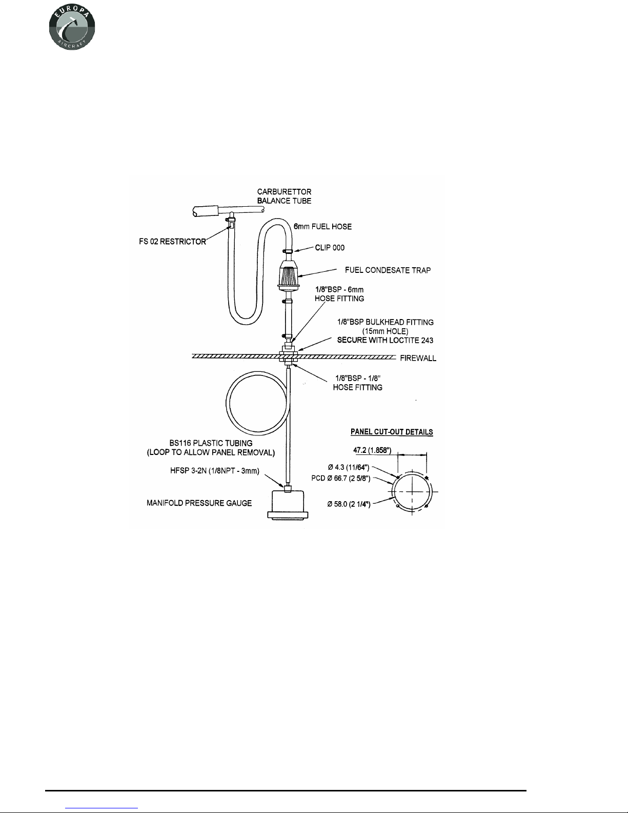
Manifold pressure gauge
A manifold pressure gauge, calibrated to read between 10 in. Hg and 50 in. Hg, is provided, along
with all the necessary parts to plumb it into the engine. The position of the gauge is suggested to be
beside the tachometer.
Refer to the diagram in figure 4 for all the connections.
Propeller drive lugs
The engine is normally delivered with the six propeller drive lugs suitable for the ground adjustable
Warp Drive propeller supplied loose. These are a light interference fit in the propeller flange,with a
relief on the forward part to assist in starting the insertion of them into the flange.
To complete the installation it will be necessary to pull them into position using a suitable bolt, nut,
and washer, with a spacer tube. Ensure that the drive lugs are fitted with no gap between the back of
the propeller flange and the drive lug collar.
Page 1 - 6
February 2005 Issue 7 Europa XS Rotax 914 Engine Manual
Fig 4. Manifold pressure gauge connections.

2. Engine controls
TheRotax912hastwoindependentcarburettors, eachoneprovidingafuel/airmixturetoonepairof
cylinders.
The only mechanical controls required for the carburettors are throttle and choke. There is a
computer controlled turbocharger wastegate control, which varies the boost pressure in response
primarily to demand from throttle position, but limited also by other functions such as RPM, static
pressure, airbox pressure and temperature, etc.
The throttle lever will be set to give engine output varying from 0% to 115% (full throttle position).
This power is available only for 5 minutes, normal continuous maximum power being 100%. Stops
on the carburettors control the 0% and 115% positions, but a gate will need to be included in the
slotted facia plate, through which the throttle lever runs, to set the 100% position. Special purpose
software is used with which to set the throttle stops, details of which are to be found in the Rotax’s
914 Engine Installation Manual
Although there are two independent throttles and chokes, there is only one throttle and one choke
control in the cockpit.
Throttle Control
A single lever, protruding through a slot inthe central spine on topof the central tunnel,provides the
pilot with throttle control. The lever is mounted and pivots in a fibreglass housing fixed to the
underside of the wheel well, and operates two separate cables.
Throttle Lever Housing
Drill the holes in the throttle lever housing, as shown in figure 1.
Page 2 - 1
Europa XS Rotax 914 Engine Manual Issue 9 April 2006
Fig 1. Throttle lever housing drilling dimensions.
Drill also a 4.8 mm hole ineach flange for mounting bolts. Open up the hole on the starboard side of
the housing to allow a socket spanner through.
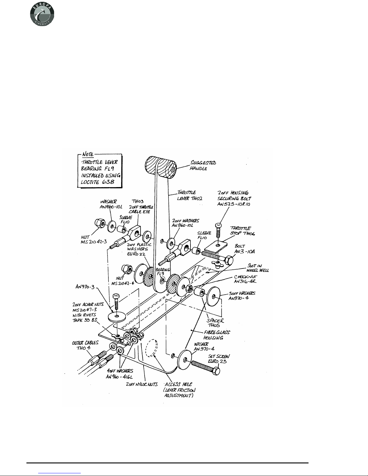
Assembly
Install the cable outers through the two holes in the housing and clamp them in position using the
nyloc nut with an AN960-416L washer each side of the fibreglass. Assemble the two cables to the
throttle lever according to figure 3 ensuring the end fittings are free to pivot. Thread the cables into
the cable outers, then install the lever into the housing as shown in figure 2, adjusting the lever
friction as desired. The friction should be sufficient to prevent the carburettor throttle lever spring
fromopeningthe throttleautomatically,andthiscanbedone afterfinalassembly.Coverthe opening
in the side of the housing to keep dirt out - a suitably sized rubber grommet would be ideal.
Page 2 - 2
November 2004 Issue 8 Europa XS Rotax 914 Engine Manual
Fig 2. Exploded diagram of throttle lever assembly.

Installation
The throttle lever housing should be positioned such that its front face is 380 mm (15") aft of the
firewall. For the monowheel aircraft this will ensure clearance with the main wheel top when it is
retracted. Mark out and cut a slot for the throttle lever in the spine in the centre tunnel then,
checking that full throttle travel is achievable, drill through the flanges for mounting bolts.
For ease of installation attach an MS21047-3 anchor nut to the underside of the housing’s flange at
each end using TLPK 424 BS rivets then, using AN525-10R10 bolts, secure the housing in place.
The front mounting will use an AN970-3 washer, see figure 2, and an AN970-3 washer can be used
temporarily to hold the rear of the mounting until it is substituted by the throttle closed stop.
Fit the throttle knob parts TH07 using an AN525-10R10 bolt and MS21042-3 nut to the top of the
throttle lever to complete the installation.
Slot the throttle cables through the gap between the firewall and the upper mounting members of the
landing gear frame, securing them to the frame with tie wraps to prevent chafing. Remove and
discard the straight cable-outer receptacle provided on each carburettor and in its place insert the
throttle cable’s threaded end. Use one check nut each side of the bracket to clamp the cable-outer in
place. Thecablesmay seemexcessivelylong,but thisistoallowlargebendradiiinthe enginebayto
ensure minimum friction.
Each throttle cable should emerge through the metal firewall on the opposite side to the carburettor
that it will control. Loop the cable up and aft towards the centre of the firewall, then down into the
bracket of the appropriate carburettor. Loosely secure the two cables where they cross.
Insert the cable inner into the nipple on the carburettor throttle lever, which is sprung to its full open
position.Settingthethrottleleverinthecockpitbackabout2-3cm(1")fromitsfullforwardposition,
screw both nipples tight onthe cables. Check for full throttle movement, making any adjustments as
required, then seal the open hole inthe throttle lever housingto prevent anything thrown upfrom the
wheel from entering.
Throttle closed stop
The addition of a throttle-closed stop is important to avoid the possibility of excess tension on the
throttle cable causing loss of throttle control. Following the method below, prepare a plate, made
from 3 mm (1/8”) aluminium, 50 mm (2”) wide. With the throttle closed, and the slow running
adjustment correctly set at the carburettors, measure the distance from the rear of the throttle lever,
whereitprotrudesabovethetopofthetunnel,tothecentreof therear4.8mm(3/16”)mountinghole.
The plate length will be 6 mm (1/4”) more than this measurement. Drill the plate 6 mm (1/4”) from
one end, bond with Redux to the tunnel, and bolt with an AN525-10R10 bolt.
Note: You should set the throttle closed stop such that a fully warmed engine idles at 1200 -
1400 rpm. Although the engine idles more smoothly at 1600 rpm or more,when landing the aircraft
you will benefit from minimal residual thrust.
Page 2 - 3
Europa XS Rotax 914 Engine Manual Issue 9 April 2006
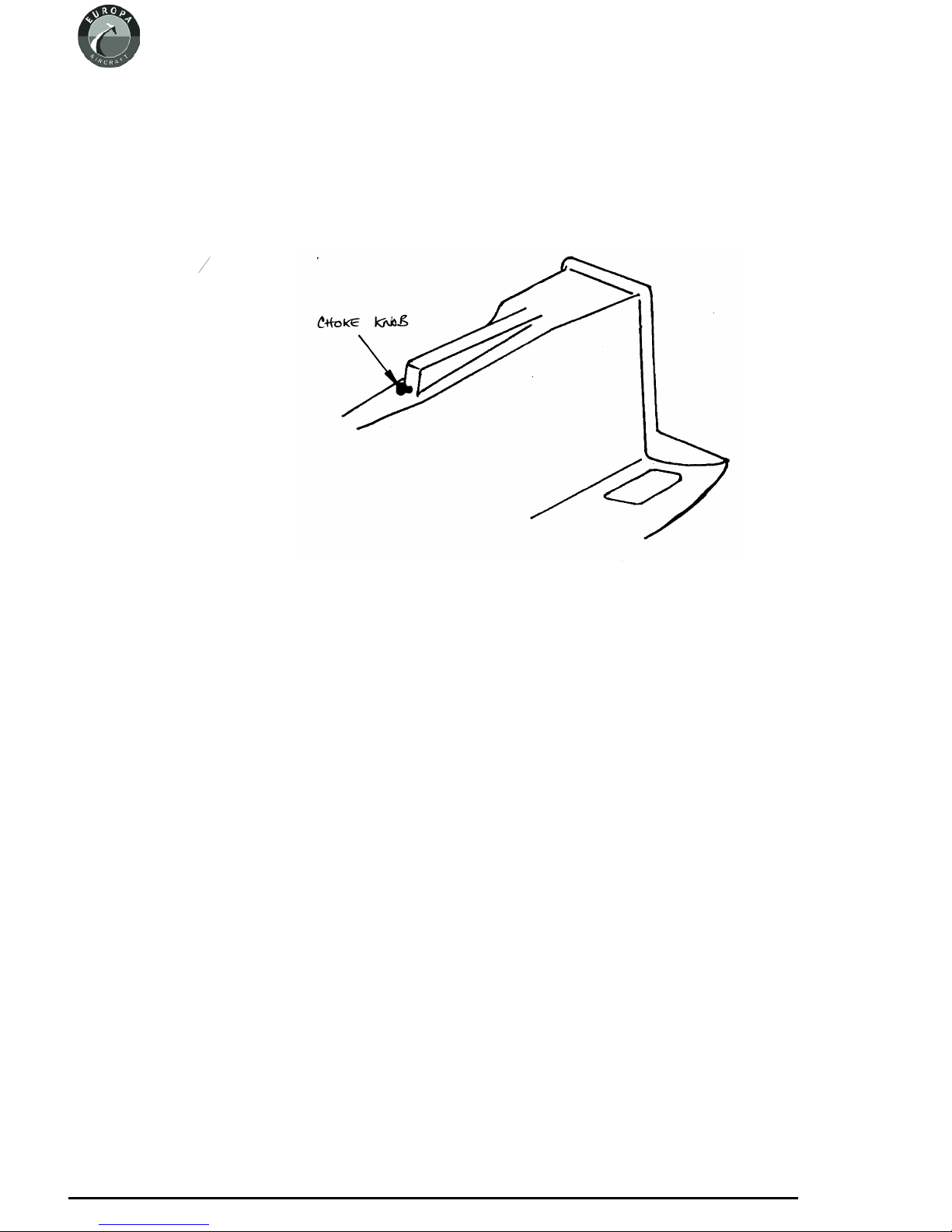
Choke Control
The two choke control cables are swaged together into the choke operating knob but run in separate
outer sleeves which are swaged into a housing.
Installation
Drill a 13 mm (12“)
diameter hole as low
as possible in the
back face of the
throttlelever spine of
thecockpitmoulding
for the cable outer
assembly to go
through. See figure
3.
Push the threaded
portion of the
cable-outer housing
through the hole and
clampitinplacewith
the lock washer and
knurled nut.
Note : As it can be difficult to insert the two cables into their respective outers, remove the plastic
knob instead leaving the cables installed when mounting the outer to the cockpit module.
The choke cables should emerge through the metal firewall as do the throttle cables. Loop these
cables forward over the top of the engine so that they enter the 90° elbow guides mounted on the
carburettor from the front. Rotate the elbows so that the cables enter them as straight as possible.
Push the cables into the carburettor cable guides and secure the cables to the choke levers using the
solderless nipples. Ensure that the choke knob is fully in and the choke levers are fully down at the
same time and that full choke movement can be achieved.
SqueezesiliconeRTV aroundthe cables where they come through thefirewallandsecurethemwith
a cable tie to the engine mounting frame to prevent them from chafing.
To ensure that the cables don’t come out of their guides, use locking wire wrapped around the cable
outer and also the cable guides.
Page 2 - 4
April 2006 Issue 9 Europa XS Rotax 914 Engine Manual
Fig 3.Position of choke control.
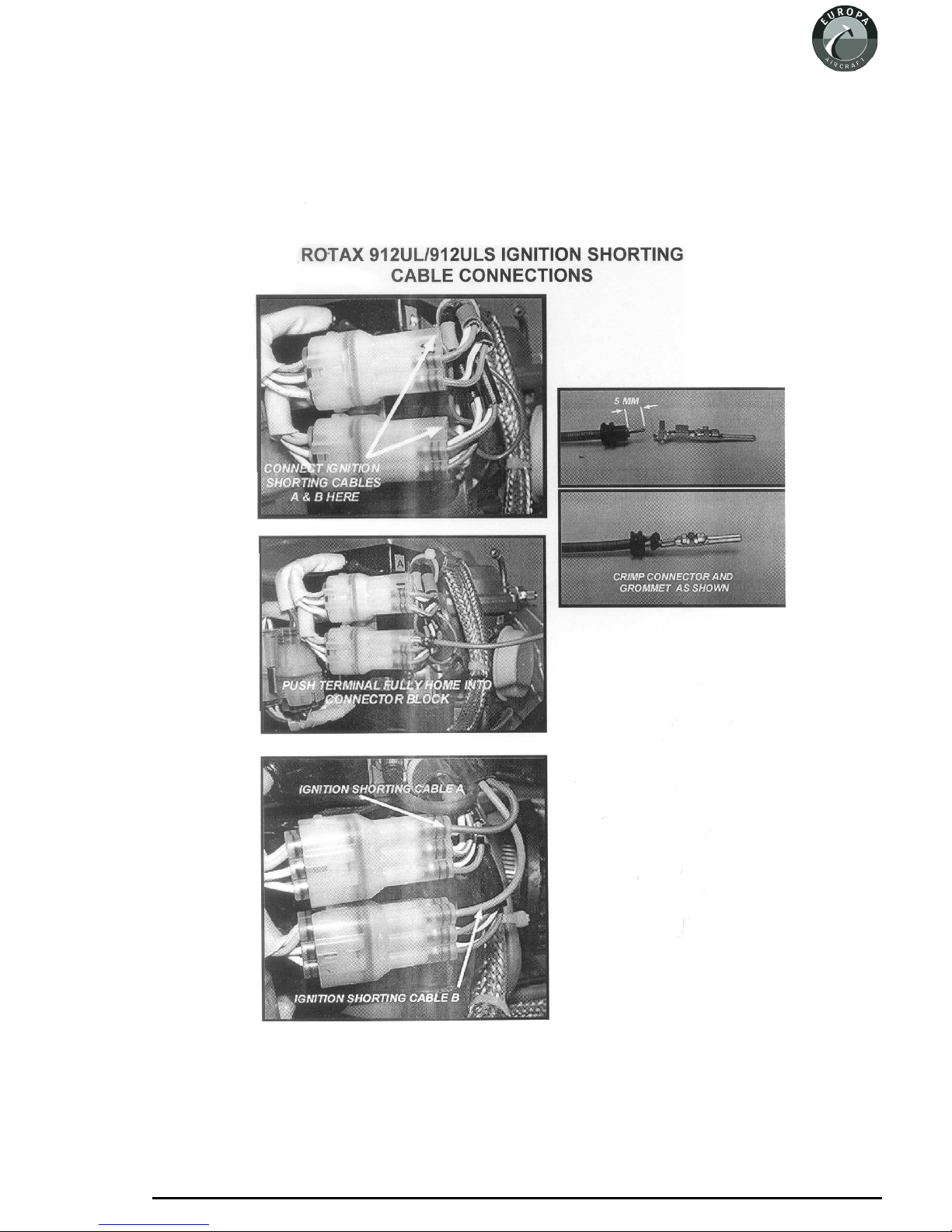
Ignition shorting cables connection
RecentRotax engineshavemodified ignitionshortingcable connections. Thephotographsin figure
4 are self-explanatory.
Page 2 - 5
Europa XS Rotax 914 Engine Manual Issue 10 November 2007
Fig 4. Ignition shoring cables connection.

INTENTIONALLY BLANK
Page 2 - 6
November 2007 Issue 10 Europa XS Rotax 914 Engine Manual

3. Oil tank
Oil Tank Mounting Bracket
The oil tank is to bemounted to the front of the starboard footwell using a steel bracket. To make the
mounting bracket first mark out and cut out the steel sheet LB01 according to the drawing at the end
of this chapter. Next, bend the central wide portion into a curve to match the outside of the oil tank.
This can be accomplished by running the metal backwards and forwards across the corner of a
wooden bench whilst applying a bending force on it.
Finally, bend the lugs each side of the curved portion so that the two narrow flanges can sit flat
against the footwell front face. See figure 1. Bending can be done by clamping the steel between
lengths of wood in a vice. Try to avoid a sharp bend radius, a 10mm (3/8") radius is ideal.
Makea90°anglebracketfromthenarrowstripshownonthetemplateandrivetittothetoprightport
side using TLPD424BS rivets -it should fit on top of the footwell.
Bracket installation
Arranging the bracket with the upper lug fitting under the oil tank lid, fasten the bracket to the tank
usingthetwonumber6Xsizejubileeclips. Keeptheclampsawayfromtheradiusofthebracket.
Withtheengineandlowercowlinginplacepositiontheoiltankandbracketontothefrontfaceofthe
starboard side footwell. Position the tank so that there is reasonable clearance from both the engine
and cowling.
Page 3 - 1
Europa XS Rotax 914 Engine Manual Issue 4 September 2001
Fig 1. Oil tank mounting bracket.
Drill through the bracket into the forward and top surfaces of the starboard footwell and bolt it in
place using AN525-10R10 bolts and MS21042-3 nuts with AN970-3 large area washers on the
inside to spread the load .
Oil tank installation
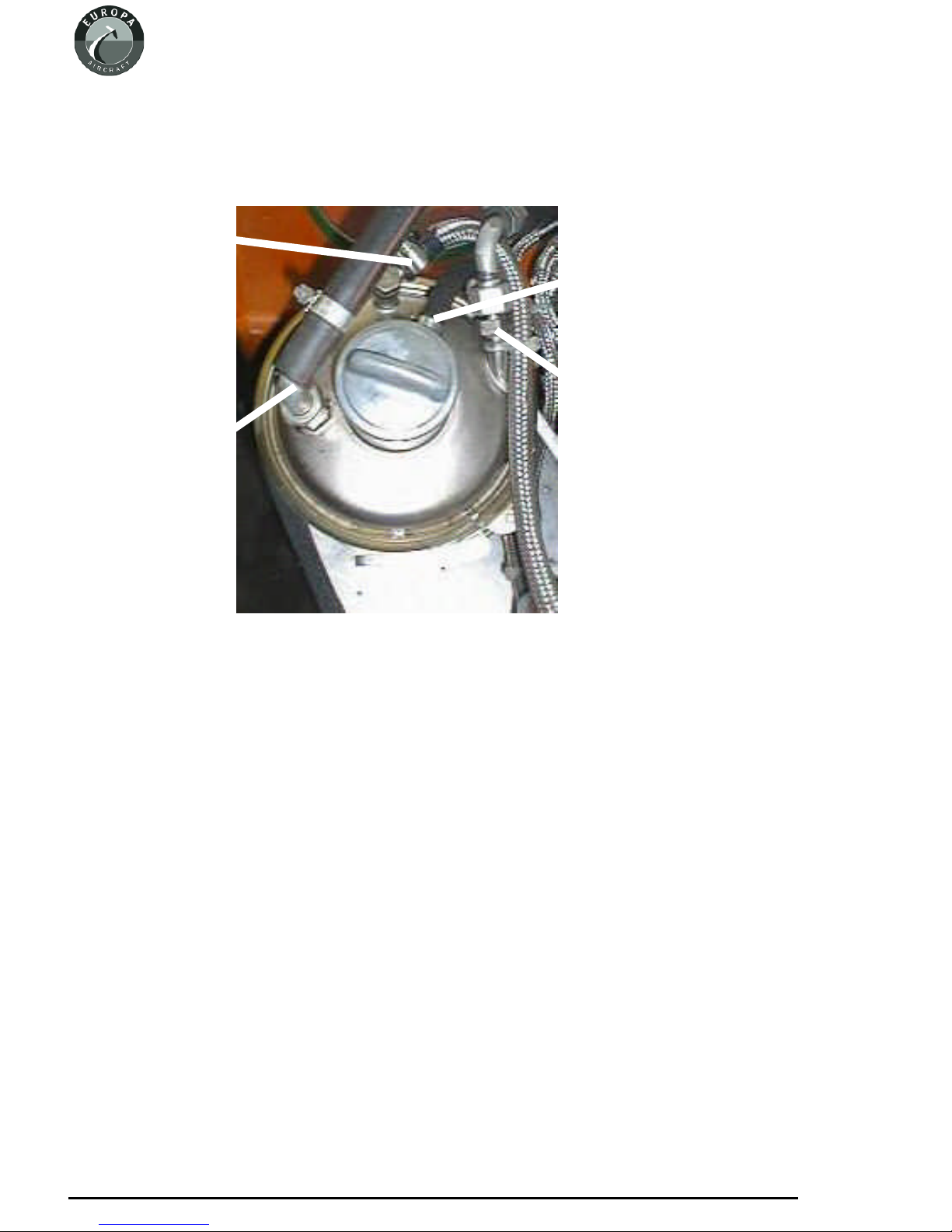
Reinstalltheoiltanktoitsmountingbracketandorientateitsothattheoiltankreturnfitting,whichis
identified as the pipe which enters the tank at a tangent, is pointing to aft and slightly to starboard.
Screw the two 90° elbow fittings to the tank fittings, arranging the tank return fittings as shown in
figure 2. Connect up the hoses to the tank as shown in figure 2.
Oil tank vent
The vent from the oiltank allows an oil mist to escape toatmosphere. It is not unusual torun the vent
linetothebottomofthecowling,howeverifyoudothis,don’tpositiontheendofthetubesuchthatit
will be in the airstream whilst flying. This could cause low pressure at the end of the tube to suck
more oil from the tank than it should.
Another consideration is that the oil mist will tend to coat the fuselage if left to vent freely. To avoid
this you can run the vent line into a collector bottle before it goes to atmosphere; however, no bottle
is provided.
Page 3 - 2
September 2001 Issue 4 Europa XS Rotax 914 Engine Manual
To oil c oole r
To oil pum p
Vent line
Re turn from sum p
Fig 2. Oil tank connections.

4. Cooling duct and coolers
Overview
A duct is fabricated from aluminium sheet to direct cooling air to the oil cooler and radiator, which
are arranged one behind the other, with the radiator in front of the oil cooler. The duct is open at the
bottom and uses the inside of the bottom cowling as the lower seal.
Duct
Figures 1 shows the assembly of the aluminium duct from the individual components.
Page 4 - 1
Europa XS Rotax 914 Engine Manual Issue 4 September 2001
Fig 1. Assembly of cooling duct.
Check the fit of the duct in between the footwells, and if necessary adjust the width of the duct, then
rivet the CD1, CD2 and CD3 sections together using TAPD46BS rivets.
Rivet sealing strip to the bottom sides of the duct using TAPD46BS rivets with EUR011 load
spreading washers to prevent the rivets pulling through the sealing material.
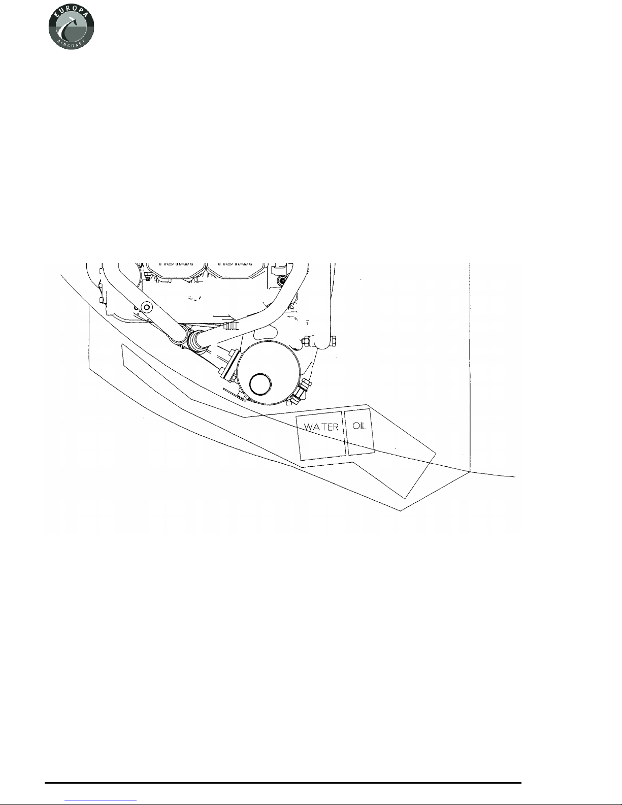
The assembled duct is fitted to the footwell using three bolts each side. The height and angle of the
duct should be arranged to provide a clearance underneath the exhaust silencer of approximately 5
mm, and be arranged to fit the air intake opening in the lower cowling. See figure 2.
A single AN3-5A bolt screws the side of the duct onto the inside face of the footwell using an
MS21047-3 anchor nut, installed in reverse into the footwell using TAPK 36 BS rivets to make it
nearly flush; the brackets CD4 and CD5 are then bolted to the duct and to the front faces of the
footwell,again usingAN3-5Abolts -theseshould haveAN970-3washerstospreadthe loadintothe
fibreglass structure, and MS21042-3 stiffnuts.
Page 4 - 2
June 2004 Issue 7 Europa XS Rotax 914 Engine Manual
Fig 2. Approximate position of duct.
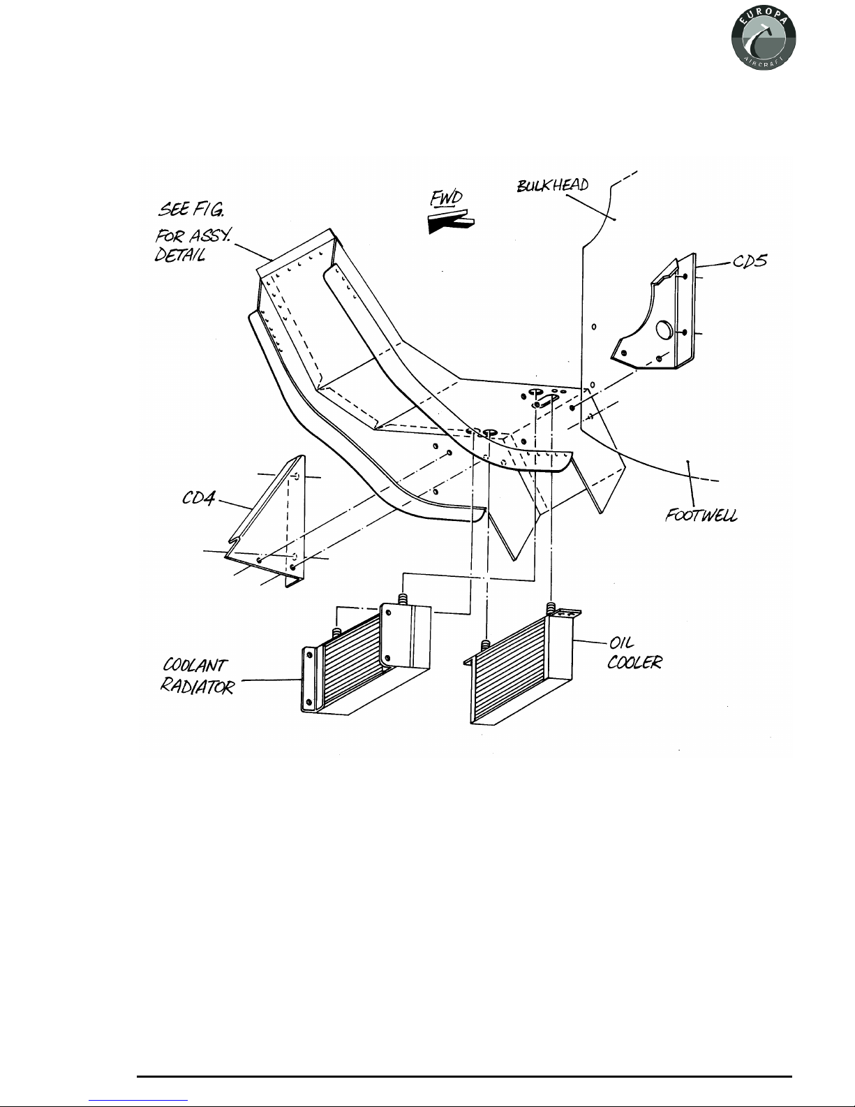
Figure 3 illustrates the mounting of the duct and the coolers.
Page 4 - 3
Europa XS Rotax 914 Engine Manual Issue 4 September 2001
Fig 3. Installation of duct and coolers.

The photographs, figures 4 and 5 illustrate the duct installation.
To ensure adequate cooling it will be necessary to blank off the gap between the bottom of the
radiator and the lower cowling
Oil cooler
The oil cooler is mounted behind the radiator and is bolted to the duct top plate CD1 with four
AN4-5AboltsandMS21042-4stiffnuts. Twounionsaresupplied-onestraightandonerightangled.
Fit these so that the straight fitting is on the starboard side.
Toimproveoilcoolinginhotclimatestheoilcoolercanbeloweredapproximately2”(50mm)sothat
it fits against the lower cowling; use longer bolts with appropriate spacers. In this case the blanking
plate fitted below the radiator will not be needed.
Fordetailsoftheoilsystemconnectionsseetheschematicviewatfigure9attheendofthischapter.
Page 4 - 4
September 2001 Issue 4 Europa XS Rotax 914 Engine Manual
Fig 4. Side view of duct.
Fig 5. Front view of duct
showing radiator
(non-typical exhaust shown).
Table of contents
Popular Engine manuals by other brands

MTU
MTU 12 V 4000 G73 operating instructions

O.S. engine
O.S. engine IL-300 Owner's instruction manual

Ametek
Ametek dunkermotoren BG 66x25 dMove Translation of the original function and connection guide

Yanmar
Yanmar 6LY3-STC Operation manual

Chamberlain
Chamberlain MotorLift RA20F instructions

Briggs & Stratton
Briggs & Stratton 120000 Operator's manual


