Yamaha Z250D User manual

Z250D
LZ250D
SERVICE MANUAL
60V-28197-3E-11
290484

NOTICE
This manual has been prepared by Yamaha primarily for use by Yamaha dealers and their trained
mechanics when performing maintenance procedures and repairs to Yamaha equipment. It has
been written to suit the needs of persons who have a basic understanding of the mechanical and
electrical concepts and procedures inherent in the work, for without such knowledge attempted
repairs or service to the equipment could render it unsafe or unfit for use.
Because Yamaha has a policy of continuously improving its products, models may differ in detail
from the descriptions and illustrations given in this publication. Use only the latest edition of this
manual. Authorized Yamaha dealers are notified periodically of modifications and significant
changes in specifications and procedures, and these are incorporated in successive editions of this
manual.
Important information 1
Particularly important information is distinguished in this manual by the following notations:
The Safety Alert Symbol means ATTENTION! BECOME ALERT! YOUR SAFETY IS
INVOLVED!
WARNING
Failure to follow WARNING instructions could result in severe injury or death to the machine
operator, a bystander, or a person inspecting or repairing the outboard motor.
CAUTION:
A CAUTION indicates special precautions that must be taken to avoid damage to the out-
board motor.
NOTE:
A NOTE provides key information to make procedures easier or clearer.
CAUTION:
USE UNLEADED STRAIGHT GASOLINE ONLY
• Gasoline containing lead can cause performance loss and engine damage.
• Do not use gasoline mixed with oil during the break-in period or anytime thereafter.
YAMALUBE 2-STROKE OUTBOARD OIL IS RECOMMENDED.
Z250D, LZ250D
SERVICE MANUAL
©2002 by Yamaha Motor Co., Ltd.
1st Edition, August 2002
All rights reserved.
Any reprinting or unauthorized use
without the written permission of
Yamaha Motor Co., Ltd.
is expressly prohibited.
Printed in the Netherlands

Contents
General information 1
GEN
INFO
Specifications 2
SPEC
Periodic checks and adjustments 3
CHK
ADJ
Fuel system 4
FUEL
Power unit 5
POWR
Lower unit 6
LOWR
Bracket unit 7
BRKT
Electrical systems 8
ELEC
Troubleshooting 9
TRBL
SHTG
Index
–+

GEN
INFO
60V3E11
General information
How to use this manual.................................................................................1-1
Manual format............................................................................................1-1
Symbols.....................................................................................................1-2
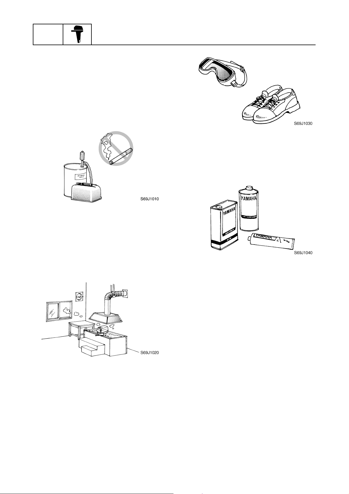
Safety while working......................................................................................1-3
Fire prevention...........................................................................................1-3
Ventilation..................................................................................................1-3
Self-protection ...........................................................................................1-3
Parts, lubricants, and sealants ..................................................................1-3
Good working practices .............................................................................1-4
Disassembly and assembly .......................................................................1-4
Identification...................................................................................................1-5
Applicable models .....................................................................................1-5
Serial number ............................................................................................1-5
Features and benefits....................................................................................1-6
Cylinder body and cylinder head ...............................................................1-6
Pistons and connecting rods .....................................................................1-7
Fuel injection pumps..................................................................................1-8
Flywheel magnet .......................................................................................1-9
ECM (Electronic Control Module) ............................................................1-10
Injector drivers .........................................................................................1-12
Idle silencer .............................................................................................1-13
Power unit mounting bolts .......................................................................1-14
Cooling water inlet ...................................................................................1-15
Transmission components.......................................................................1-16
Technical tips ...............................................................................................1-17
Electronic control system.........................................................................1-17
Partial cylinder operation .........................................................................1-18
Fail-safe control .......................................................................................1-19
Warning control .......................................................................................1-20
Over-revolution control ............................................................................1-20
Shift cut control........................................................................................1-20
Propeller selection.......................................................................................1-21
Propeller size...........................................................................................1-21
Selection..................................................................................................1-21

60V3E11
1
2
3
4
5
6
7
8
9
Predelivery checks ......................................................................................1-22
Checking the fuel system ........................................................................1-22
Checking the gear oil level ......................................................................1-22
Checking the engine oil level...................................................................1-22
Checking the battery................................................................................1-23
Checking the outboard motor mounting height........................................1-23
Checking the remote control cables ........................................................1-23
Checking the steering system .................................................................1-24
Checking the gear shift and throttle operation.........................................1-24
Checking the power trim and tilt system..................................................1-24
Checking the engine start switch and engine shut-off switch..................1-24
Checking the cooling water pilot hole ......................................................1-25
Test run ...................................................................................................1-25
Break-in ...................................................................................................1-25
After test run ............................................................................................1-25

GEN
INFO General information
1-1 60V3E11
How to use this manual 1
Manual format
The format of this manual has been designed to make service procedures clear and easy to under-
stand. Use the information below as a guide for effective and quality service.
1Parts are shown and detailed in an exploded diagram and are listed in the components list.
2Tightening torque specifications are provided in the exploded diagrams and after a numbered
step with tightening instructions.
3Symbols are used to indicate important aspects of a procedure, such as the grade of lubricant
and lubrication point.
4The components list consist of part names and part quantities, as well as bolt and screw dimen-
sions.
5Service points regarding removal, checking, and installation are shown in individual illustrations
to explain the relevant procedure.
NOTE:
For troubleshooting procedures, see Chapter 9, “Troubleshooting.”
LOWR Lower unit
6-5 62Y5A11
Lower unit
No. Part name Q’ty Remarks
1 Lower unit 1
2 Plastic tie 1 Not reusable
3Hose 1
4 Check screw 1
5 Gasket 2 Not reusable
6 Dowel pin 2
7 Bolt 4 M10 40 mm
8 Drain screw 1
9Grommet 1
10 Bolt 1 M10 45 mm
11 Bolt 1 M8 60 mm
12 Thrust washer 1
13 Propeller 1
14 Washer 1
15 Washer 1
16 Cotter pin 1 Not reusable
17 Propeller nut 1
18 Trim tab 1
LOWR Lower unit
6-19 62Y5A11
Removing the drive shaft
1. Remove the drive shaft assembly and
pinion, and then pull out the forward
gear.
Disassembling the drive shaft
1. Install the pinion nut 1, tighten it finger
tight, and then remove the drive shaft
bearing 2using a press.
CAUTION:
• Do not press the drive shaft threads a
directly.
• Do not reuse the bearing, always
replace it with a new one.
Disassembling the forward gear
1. Remove the taper roller bearing from the
forward gear using a press.
CAUTION:
Do not reuse the bearing, always replace
it with a new one.
2. Remove the needle bearing from the for-
ward gear.
CAUTION:
Do not reuse the bearing, always replace
it with a new one.
Drive shaft holder 4 1: 90890-06518
Pinion nut holder 2: 90890-06505
Socket adapter 2 3: 90890-06507
Bearing inner race attachment 3:
90890-06639
S62Y6850K
Bearing separator 1: 90890-06534
Stopper guide plate 2: 90890-06501
Stopper guide stand 3:
90890-06538
Bearing puller 4: 90890-06535
Bearing puller claw 1 5:
90890-06536
S62Y6740K
5
4
321

60V3E11 1-2
1
2
3
4
5
6
7
8
9
Symbols
The symbols below are designed to indicate the content of a chapter.
General information
Specifications
Periodic checks and adjustments
Fuel system
Power unit
Lower unit
Bracket unit
Electrical systems
Troubleshooting
GEN
INFO
SPEC
CHK
ADJ
FUEL
POWR
LOWR
BRKT
ELEC
TRBL
SHTG
–+
Symbols 1to 6indicate specific data.
1Special tool
2Specified oil or fluid
3Specified engine speed
4Specified tightening torque
5Specified measurement
6Specified electrical value
(resistance, voltage, electric current)
Symbols 7to Bin an exploded diagram indicate the grade of lubricant and the lubrication point.
7Apply 2-stroke outboard motor oil
8Apply water resistant grease (Yamaha grease A)
9Apply molybdenum disulfide grease
0Apply corrosion resistant grease
(Yamaha grease D)
AApply low temperature resistant grease
(Yamaha grease C)
BApply injector grease
Symbols Cto Hin an exploded diagram indicate the type of sealant or locking agent and the appli-
cation point.
CApply Gasket Maker
DApply Yamabond No. 4
EApply LOCTITE 271 (red)
FApply LOCTITE 242 (blue)
GApply LOCTITE 572
HApply silicon sealant
123456
T
R
.
.
7890AB
E
A M
D
CI
CDEFGH
GM
4
271
LT
242
LT
572
LT SS
How to use this manual

GEN
INFO General information
1-3 60V3E11
Safety while working 1
To prevent an accident or injury and to
ensure quality service, follow the safety pro-
cedures provided below.
Fire prevention
Gasoline is highly flammable.
Keep gasoline and all flammable products
away from heat, sparks, and open flames.
Ventilation
Gasoline vapor and exhaust gas are heavier
than air and extremely poisonous. If inhaled
in large quantities they may cause loss of
consciousness and death within a short time.
When test running an engine indoors (e.g., in
a water tank) be sure to do so where ade-
quate ventilation can be maintained.
Self-protection
Protect your eyes by wearing safety glasses
or safety goggles during all operations involv-
ing drilling and grinding, or when using an air
compressor.
Protect your hands and feet by wearing pro-
tective gloves and safety shoes when neces-
sary.
Parts, lubricants, and sealants
Use only genuine Yamaha parts, lubricants,
and sealants or those recommended by
Yamaha, when servicing or repairing the out-
board motor.
Under normal conditions, the lubricants men-
tioned in this manual should not harm or be
hazardous to your skin. However, you should
follow these precautions to minimize any risk
when working with lubricants.
1. Maintain good standards of personal and
industrial hygiene.
2. Change and wash clothing as soon as
possible if soiled with lubricants.
3. Avoid contact with skin. Do not, for
example, place a soiled rag in your
pocket.
4. Wash hands and any other part of the
body thoroughly with soap and hot water
after contact with a lubricant or lubricant
soiled clothing has been made.
5. To protect your skin, apply a protective
cream to your hands before working on
the outboard motor.

60V3E11 1-4
1
2
3
4
5
6
7
8
9
6. Keep a supply of clean, lint-free cloths for
wiping up spills, etc.
Good working practices
Special service tools
Use the recommended special service tools
to protect parts from damage. Use the right
tool in the right manner—do not improvise.
Tightening torques
Follow the tightening torque specifications
provided throughout the manual. When tight-
ening nuts, bolts, and screws, tighten the
large sizes first, and tighten fasteners starting
in the center and moving outward.
Non-reusable parts
Always use new gaskets, seals, O-rings, cot-
ter pins, circlips, etc., when installing or
assembling parts.
Disassembly and assembly
1. Use compressed air to remove dust and
dirt during disassembly.
2. Apply engine oil to the contact surfaces
of moving parts before assembly.
3. Install bearings with the manufacture
identification mark in the direction indi-
cated in the installation procedure. In
addition, be sure to lubricate the bearings
liberally.
4. Apply a thin coat of water-resistant
grease to the lip and periphery of an oil
seal before installation.
5. Check that moving parts operate nor-
mally after assembly.
Safety while working

GEN
INFO General information
1-5 60V3E11
Identification 1
Applicable models
This manual covers the following models.
Serial number
The outboard motor serial number is
stamped on a label attached to the port
clamp bracket.
1Model name
2Approved model code
3Transom height
4Serial number
Applicable models
Z250DETO, LZ250DETO
Model name Approved
model code
Starting
serial No.
Z250DETO 60V X: 1000001–
U: 1000001–
LZ250DETO 60W X: 1000001–
U: 1000001–

60V3E11 1-6
1
2
3
4
5
6
7
8
9
Features and benefits 1
Cylinder body and cylinder head
Hemispherical combustion chambers have been incorporated in the cylinder head to realize a high
compression ratio of 6.2.
The exhaust ports have been chamfered to reduce loss of the exhaust gases.
Also, an exhaust shell has been adopted to allow exhaust gases flow out smoothly.
The plateau honing process has been used in the cylinder sleeves to reduce friction.
The spark plugs have been offset from the center of the cylinder head to keep the fuel injectors
away from high temperatures.
The fuel injectors are located on the exhaust side of the combustion chambers. Fuel is injected
toward the tumble due to scavenging to obtain the optimum air-fuel mixture.
Special twin corrugated washers have been adopted in the injectors to prevent fuel in an injector
from carbonizing due to exhaust heat.
NOTE:
Install the washers so that the shorter metal guard ends contact each other.
1Injector
2Spark plug
3Corrugated washers
S60V1130
1
2
3
Identification / Features and benefits

GEN
INFO General information
1-7 60V3E11
Pistons and connecting rods
The pistons and connecting rods have been processed as follows to increase durability.
•Heat resisting, lightweight aluminum forged pistons have been adopted.
•Highly carbonized connecting rods have been adopted.
•The piston rings have been processed with a hard chrome plating that has a thickness of 50
microns.
•The big end bearings have been processed with 18 rollers, 2 rollers more than those of the VX250
(250C), and with oil grooves around the outer race of the bearings.
•The small ends of the connecting rods have been processed with a special heat treatment.
•Oil grooves have been processed around the outer peripheries of the 2nd piston rings.
12nd piston ring
ÈOil groove
S60V1140
1
È

60V3E11 1-8
1
2
3
4
5
6
7
8
9
Fuel injection pumps
Twin fuel injection pumps with pressure regulators have been adopted to obtain a high fuel pressure
of 7 MPa (71 kg/cm2, 1,015 psi).
The fuel injection pressure is detected by the fuel pressure sensor installed on the fuel rail. Protec-
tors have been incorporated on the fuel pressure sensor to reduce vibrations conducting to the sen-
sor.
High-pressure fuel injection obtains a better air-fuel mixture due to finer atomization.
CAUTION:
Do not disassemble the fuel injection pumps. The proper facilities and special service tools
are required to reassemble them.
1Fuel pump drive unit
2High-pressure fuel pump with
pressure regulator
3Fuel return hose
4Pressure equalizing pipe
5Fuel pressure sensor
6Fuel rail
7Injector #1
8Injector #2
9Injector #3
0Injector #4
AInjector #5
BInjector #6
ÈMedium-pressure fuel
(suction)
ÉHigh-pressure fuel
ÊFuel return
S60V1150
: È
: É
: Ê
3
1
2
3
4
5
6
2
8
0
B
7
9
A
Features and benefits

GEN
INFO General information
1-9 60V3E11
Flywheel magnet
A large capacity Rectifier Regulator has been adopted to obtain a charging current of 50 amperes
for battery charging capabilities.
An isolator has been incorporated into the Rectifier Regulator unit.
NOTE:
An optional battery charging cable has been made available for use with an accessory battery.
1Fuse
2Battery 1
3Battery 2
4Lighting coil
5Control circuit
6Blue
7Black
8Rectifier Regulator unit
9Isolator cable (optional)
ÈCharging circuit
ÉCharging output
ÊCharging current (A)
ËEngine speed (r/min)
S60V1160
G
R
R
G
G
B
93 mm (3.66 in)
3.8 m (12.5 ft) / 2.7 m (9 ft)
88 mm (3.46 in)
1
2
3
4
4
È
É
0
55
1,000 2,000 3,000 4,000 5,000 6,000
Ê
Ë
10
15
20
25
30
35
40
45
50
5
8
7
6
P/No. 69J-81949-00 (3.8 m [12.5 ft])
68F-81949-00 (2.7 m [9 ft])
B
7
R
R
G
G
G
B
9

60V3E11 1-10
1
2
3
4
5
6
7
8
9
ECM (Electronic Control Module)
A small and lightweight ECM has been adopted to make the surrounding components compact.
Silicon grommets (navy blue) have been adopted for installing the ECM and injector driver brackets,
and to reduce vibration conducting from the engine.
CAUTION:
Do not apply fuel or oil to the grommets, otherwise they can be damaged.
1Silicon grommet (navy blue)
2ECM and injector drivers mounting bracket
S60V1170
168 mm (6.61 in)
180 mm (7.09 in)
126 mm (4.96 in)
Z200
Z200N
Z250
Z250D
135 mm (5.31 in)
ECM
ECM
S60V1180
1
2
Features and benefits

GEN
INFO General information
1-11 60V3E11
A large cover has been adopted to protect the electrical components from water.
1Large electrical component cover
The memory in the ECM has been increased from 128 bytes to 256 bytes to expand the functions of
the YDIS.
A communication cable with a USB connector has been made available.
1USB connector
S60V1190
1
S60V1200
1

60V3E11 1-12
1
2
3
4
5
6
7
8
9
Injector drivers
Twin small and lightweight injector drivers have been adopted to make the surrounding components
compact.
Maintenance has been made easy and low cost for replacing the driver has been obtained.
S60V1210
170 mm (6.69 in)
96 mm (3.78 in)
180 mm (7.09 in)
175 mm (6.89 in)
Z200
Z200N
Z250
Z250D
Features and benefits

GEN
INFO General information
1-13 60V3E11
Idle silencer
An idle silencer has been incorporated in the bottom cowling.
Exhaust gases are led into the idle silencer from the upper case and expanded, and then dis-
charged into the atmosphere.
The idle hole has been positioned higher at the rear of the bottom cowling to decrease the resis-
tance of the exhaust back pressure.
1Upper case
2Silencer
3Idle hole
4Atmosphere
ÈExhaust gas/water
ÉWater
S60V1220
2
1
3 4
: È
: É

60V3E11 1-14
1
2
3
4
5
6
7
8
9
Power unit mounting bolts
Bolts coated with a sealing agent have been adopted to provide a sealing function to the bolts. The
sealing agent secures the axial force of the bolts after they are tightened to the specified torque,
thus preventing the bolts from coming loose. The sealing agent also helps prevent the bolts from
sticking if salt water enters into the thread holes and crystallizes.
Also, the bolts can be removed even if corroded particles have collected in and choked the bolt
holes because the sealing agent also acts as an insulator. As a result, servicing such as removing
the power unit has been made easy.
NOTE:
Clean the bolt surface, and then apply LOCTITE 572 to the bolt to act as a sealing agent when reus-
ing the power unit mounting bolts.
1Sealing agent coating
2Bolt
3Cylinder block
4Sealing agent
5Upper case
6Corroded particles
ÈPower unit mounting bolt
ÉBolt hole description
S60V1230
23
4
5
6
È
É
1
Features and benefits
Other manuals for Z250D
2
This manual suits for next models
1
Table of contents
Other Yamaha Engine manuals

Yamaha
Yamaha E115A User manual

Yamaha
Yamaha F150A User manual

Yamaha
Yamaha MX825V-EFI User manual

Yamaha
Yamaha MX-800 User manual

Yamaha
Yamaha F50D Building instructions

Yamaha
Yamaha F60C User manual

Yamaha
Yamaha EH64 User manual

Yamaha
Yamaha MX775 User manual

Yamaha
Yamaha MZ300 User manual

Yamaha
Yamaha MX175 User manual

Yamaha
Yamaha MA175 User manual

Yamaha
Yamaha MX800V User manual

Yamaha
Yamaha YDS3 User manual

Yamaha
Yamaha YF200 R1 User manual

Yamaha
Yamaha VF150 User manual

Yamaha
Yamaha F150B User manual

Yamaha
Yamaha 40XMH User manual

Yamaha
Yamaha MT110 User manual

Yamaha
Yamaha F2.5D User manual

Yamaha
Yamaha F50F User manual