Eurotec MBM MINIMA GC66 User manual

CUOCIPASTA GAS SERIE MINIMA
SECONDO NORMA: EN 437 e EN 203 parte 1 e 2 Categoria II per Gas Metano e G.P.L.
GAS HEATED PASTA COOKERS SERIE MINIMA
ACCORDING TO: EN 437 and EN 203 part 1 and 2 Cat. II for Natural gas and L.P.G.
CUISEUR DE PATES GAZ SERIE MINIMA
CONFORME AUX NORMES: EN 437 et EN 203 1ère et 2ème partie pour Gaz Méthane et G.P.L.
GAS BEHEIZTE NUDELKOCHER SERIE MINIMA
NACH: EN 437 und EN 203 Teil 1 und 2 Kategorie II für Erdgas und Flüssiggas
COCEDORES DE PASTA GAS SERIE MINIMA
SEGÚN: EN 437 y EN 203 parte 1 y 2. Categoría II: Metano y G.P.L.
04/12/2009 Rev. 4 IMCU600019
GC66
ISTRUZIONI PER L’INSTALLAZIONE, L’USO E LA MANUTENZIONE
INSTALLATION, USEAND MAINTENANCE INSTRUCTIONS
INSTRUCTIONS POUR L’INSTALLATION, L’EMPLOI ET L’ENTRETIEN
INSTALLATIONS-, BETRIEBS-UND WARTUNGSANLEITUNGEN
INSTRUCCIONES PARA LA INSTALACIÓN, EL USOY EL MANTENIMIENTO
0 6 9 4
IT
GB
FR
DE
ES

- 2 -
IT
ITALIANO ................................................................................................ pagina 2 - 10
ENGLISH ................................................................................................. page 11 - 18
FRANÇAIS ............................................................................................... page 19 - 26
DEUTSCH ................................................................................................ Seite 35 - 41
ESPAÑOL ................................................................................................ página 34 - 41
CAPITOLO DESCRIZIONE PAGINA
Avvertenze generali ............................................................................................................................. 3
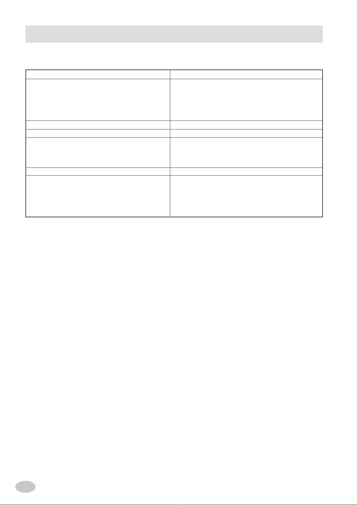
1. Dati tecnici .......................................................................................................................................... 4
1.1 Tabella I: Dati tecnici cuocipasta a gas CAT. II (Gas Metano e G.P.L.) .............................................. 4
1.2 Caratteristiche tecniche ....................................................................................................................... 4
2. Istruzioni per l’installazione ............................................................................................................... 5
2.1 Informazioni riguardanti i cuocipasta a gas serie Minima ................................................................. 5
2.2 Installazione ........................................................................................................................................ 5
2.2.1 Legge, norme e direttive tecniche da rispettare .................................................................................. 5
2.2.2 Luogo d’installazione ......................................................................................................................... 6
2.2.3 Posizionamento ................................................................................................................................... 6
2.2.4 Montaggio apparecchiature top su base armadiata ............................................................................6
2.2.5 Collegamento acqua ........................................................................................................................... 6
2.2.6 Scarico acqua....................................................................................................................................... 6
2.3 Collegamento all’impianto del gas ..................................................................................................... 6
2.4 Scarico dei prodotti di combustione ................................................................................................... 7
2.4.1 Apparecchi a gas tipo: A ..................................................................................................................... 7
2.5 Come ottenere la portata termica nominale ........................................................................................ 7
2.5.1 Controllo della pressione a monte (Pe) ............................................................................................... 7
2.5.2 Controllo della pressione all’ugello (Pi)............................................................................................. 7
2.5.3 Regolazione della portata termica minima ......................................................................................... 7
2.5.4 Controllo per il funzionamento a gas liquido .................................................................................... 7
2.6 Controllo del funzionamento .............................................................................................................. 7
2.7 Introduzione dell’utente ..................................................................................................................... 7
3. Trasformazione per funzionamento ad altro tipo di gas ..................................................................... 8
3.1 Sostituzione ugelli bruciatori principali............................................................................................. 8
3.2 Sostituzione ugello bruciatore pilota ................................................................................................. 8
4. Sostituzione dei componenti piu’ importanti ..................................................................................... 8
5. Istruzioni per l’utente .......................................................................................................................... 9
5.1 Riempimento vasca ............................................................................................................................. 9
5.2 Accensione bruciatori ......................................................................................................................... 9
5.3 Spegnimento ....................................................................................................................................... 9
5.4 Svuotamento della vasca..................................................................................................................... 9
TABELLA II: GAS, PRESSIONE E CATEGORIE NEIVARI PAESI. SECONDO EN 437 - EN 203-1-2 . 43
DATI TECNICI .................................................................................................................................... 44
SCHEMA D’INSTALLAZIONE .......................................................................................................... 56
INDICE

- 3 - IT
- Leggere attentamente le avvertenze contenute nel presente libretto in quanto forniscono importanti
indicazioni riguardanti la sicurezza di installazione, d’uso e di manutenzione.
- Conservarecon cura questolibretto per ogniulteriore consultazione deivari operatori.
- Dopo aver tolto l’imballaggio, assicurarsi dell’integrità dell’apparecchiatura e in caso di dubbio, non utilizzare
l’apparecchiaturaerivolgersi a personaleprofessionalmentequalificato.
- Primadicollegare l’apparecchiatura, accertarsichei dati riportati sullatarghettasiano corrispondenti aquellidella
rete di distribuzione gas.
- Questa apparecchiatura deve essere destinata solo all’uso per il quale è stata espressamente concepita, ogni
altro uso è da considerarsi improprio e quindi pericoloso.
- L’apparecchiatura deve essereutilizzata soloda personaaddestrataall’uso della stessa.
- Per eventuale riparazione rivolgersi solamente ad un centro di assistenza tecnica autorizzato dal costruttore e
richiedere l’utilizzo di ricambi originali.
- Ilmancato rispettodi quantosopra, può compromettere la sicurezza dell’apparecchiatura.
- Nonlavare l’apparecchiaturacon getti d’acqua diretti e ad altapressione.
- Non ostruire le aperture o feritoie di aspirazione o di smaltimento del calore.
AVVERTENZE GENERALI
La casa costruttrice declina ogni responsabilità per le possibili inesattezze contenute nel presente opuscolo, imputabili ad
errori di trascrizione o stampa. Si riserva inoltre il diritto di apportare al prodotto quelle modifiche che si ritengono utili o
necessarie, senza pregiudicare le caratteristiche essenziali.
In caso di inosservanza delle norme contenute nel presente manuale, sia da parte dell’utente che da parte del tecnico
addetto all’installazione, la Ditta declina ogni responsabilità ed ogni eventuale incidente o anomalia causato dalle
suddette inosservanze non potrà essere imputato alla stessa.
- 4 -
IT
1.1 TABELLA I: DATI TECNICI CUOCIPASTAA GAS CAT. II (GAS METANO E G.P.L.)
1.2 CARATTERISTICHE TECNICHE
Struttura portante in acciaio inox AISI 304, pannellatura e basamento in acciaio inox montata su piedini regolabili in altezza.
-VASCA in acciaio inox AISI 304.
- RISCALDAMENTOA GAS mediante bruciatori a fiamma autostabilizzata in acciaio che garantiscono un’elevata uniformità
di riscaldamento. Regolazione termostatica della temperatura con valvola di sicurezza e termocoppia per l’interruzione
dell’afflusso del gas in caso di spegnimento accidentale del bruciatore pilota. Accensione piezoelettrica al pilota.
(1) Compresa la portata termica del bruciatore pilota ca. 400 W
MODELLO
Dimensioni
Larghezza
Profondità
Altezza
Altezza totale
Scarico camino Tipo: B11
Peso netto
Camino
Dimensionivasca
Larghezza
Profondità
Altezza media
Attacco gas
Portatatermicanominale
Aria per la combust. / ventil.
Consumogas
G.P.L. G 30/31
MetanoH-G20
MetanoL-G25
Tipo
mm
mm
mm
mm
Ø mm
kg
kg
mm
mm
mm
“A”
(1) kW
m3/h
(15°C)
g/h
m3/h
m3/h
GC66
A
600
600
290
480
-
35
-
-
510
340
228,5
G1/2”
11
20
867/854
1,164
1,35
1. DATI TECNICI

- 5 - IT
L’installazione e l’eventuale trasformazione per l’uso di altri tipi di gas, deve essere eseguita da persone qualificate
secondo la normativa in vigore.
Vedere tabelle dati tecnici: 1.1.
AVVERTENZE:
Nel caso in cui l’apparecchiatura venga installata contro una parete quest’ultima deve resistere ai valori di temperatura di
100°C e deve essere incombustibile, oppure l’apparecchiatura deve essere sistemata a 10 cm. di distanza.
Prima di procedere all’installazione, togliere dal rivestimento la pellicola di protezione in plastica, eliminando gli eventuali
residui adesivi con prodotto adatto alla pulizia per l’acciaio inossidabile.
Installare l’apparecchio in posizione orizzontale, la corretta posizione si otterrà ruotando i piedini livellatori.
2.1 INFORMAZIONI RIGUARDANTI I CUOCIPASTAA GAS SERIE MINIMA
Questo libretto è valido per i nostri Cuocipasta serie Minima del tipo A1 Categoria II (Gas naturale e Liquido G.P.L.).
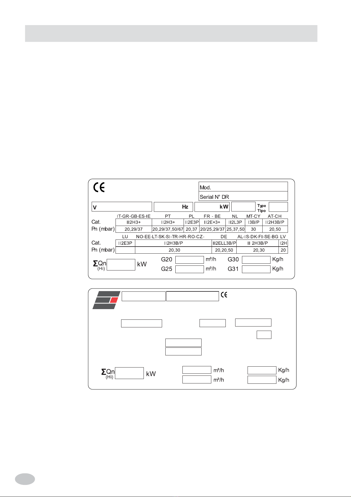
Vedere tabella 1.1. La targhetta secondo le norme EN437 e EN 203-1-2 si trova sul retro ed all’interno.
Esempio targhetta Italia:
Cat. II 2H3+
Pe = Pressione a monte
Pi = Pressione all’ugello
2. ISTRUZIONI PER L’INSTALLAZIONE
SN°Mod.
Pin.N°
Made by
Type
Cat.
Pn (mbar)
II
2HS3B/P
25,25,30/30
G 30
G 31
G 20
G 25.1
REA 16238T4 ITALY
HU
kW
Hz
20,37,50
MK
2.2 INSTALLAZIONE
2.2.1 LEGGE, NORME E DIRETTIVE TECNICHE DA RISPETTARE
Per l’installazione sono da osservare le seguenti norme:
- Prescrizioni vigenti antinfortunistiche e antincendio.
- La regolamentazione dell’ente erogatore del gas, dal quale bisogna farsi rilasciare il nullaosta prima dell’installazione.
- Norme «Installazione impianti a gas».
- Norme igieniche.

- 6 -
IT
2.2.2 LUOGO D’INSTALLAZIONE
- L’apparecchio deve essere installato in locali con sufficiente areazione. Questo apparecchio richiede una aspirazione di
almeno 2 m3/h • kW P.T. (Portata Termica).
- Installare l’apparecchiatura secondo quanto previsto dalle norme di sicurezza UNI - CIG 8723, legge N° 46 del 5-3-’90 e
D.M. N° 74 del 12.04.96.
2.2.3 POSIZIONAMENTO
- Le varie apparecchiature possono essere installate singolarmente o possono essere accoppiate ad altre apparecchiature
della nostra stessa gamma.
- Questa apparecchiatura non è idonea per l’incasso.
- La distanza dalle pareti laterali e posteriore deve essere minimo di 10 cm., nel caso in cui la distanza fosse inferiore o il
materiale delle pareti o del pavimento fossero infiammabili, è indispensabile l’applicazione di un isolante termico.
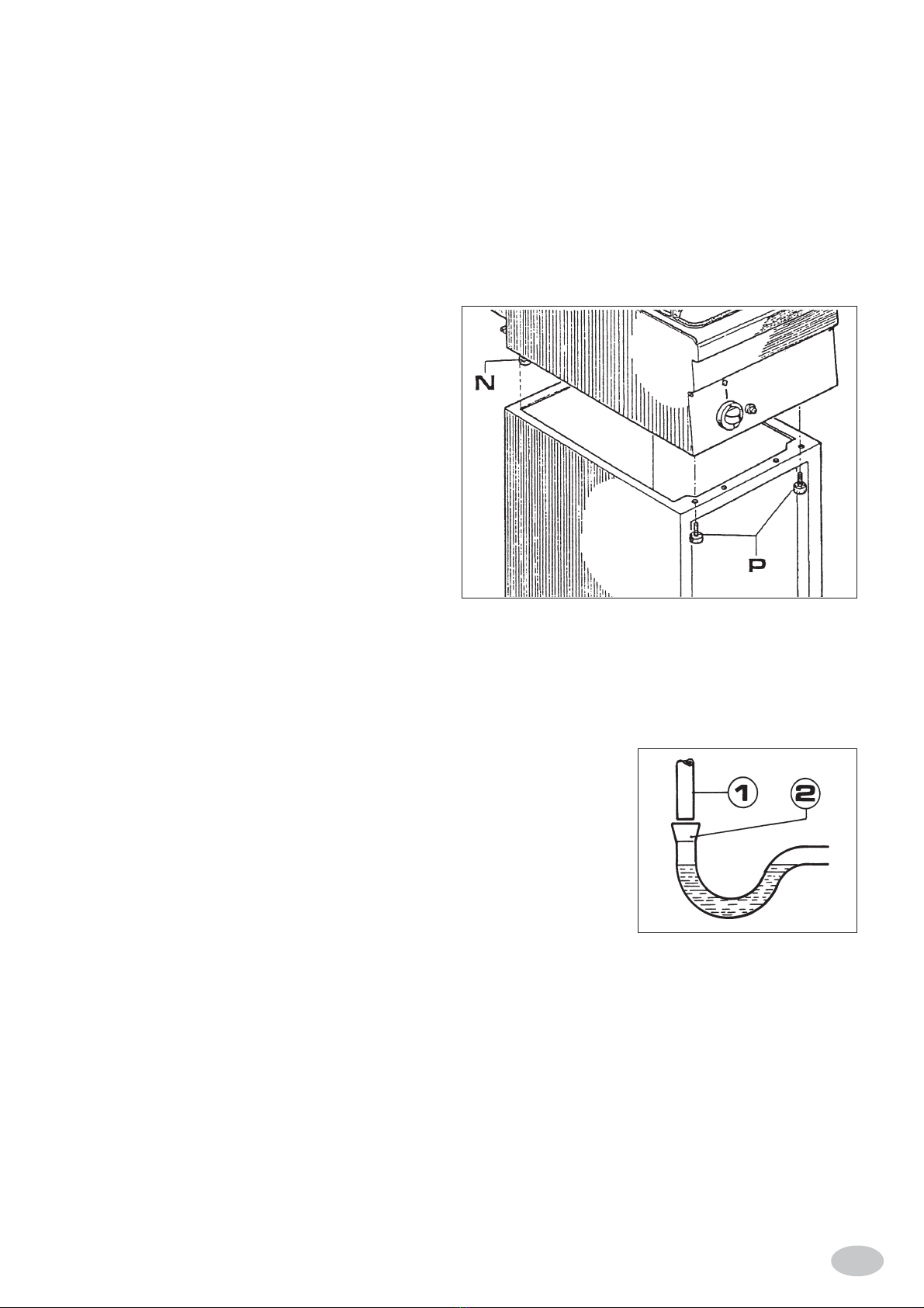
2.2.4 MONTAGGIOAPPARECCHIATURE TOP
SU BASEARMADIATA
Svitare e togliere i due piedini anteriori (P) dell’apparec-
chiatura da porre sulla base armadiata, appoggiarla poi su
questa facendo in modo che i due piedini posteriori (N)
vadano ad incastrarsi nell’angolo della base come illustrato
in figura.
Appoggiare completamente l’apparecchiatura e fissarla av-
vitando i due piedini anteriori (P) passando attraverso i fori
predisposti sulla base per il fissaggio dell’apparecchiatura.
2.2.5 COLLEGAMENTOACQUA
Pressione massima dell’acqua: 4 bar (400 kPa).
Per eseguire una corretta installazione è indispensabile
che:
- L’apparecchio venga alimentato con acqua potabile.
- Il tubo di entrata acqua sia collegato alla rete di
distribuzione mediante un rubinetto di intercettazione da chiudersi quando l’apparecchio non è in funzione o per interventi
di manutenzione.
- Tra il rubinetto di intercettazione ed il tubo che collega il cuocipasta sia installato un filtro meccanico per impedire l’immissione
di eventuali scorie ferrose che, ossidandosi, possono intaccare e determinare col tempo, l’ossidazione della vasca.
- E’ consigliabile prima di collegare l’ultimo tratto di tubazione dell’attacco del cuocipasta, lasciare defluire un certo
quantitativo di acqua per spurgare il tubo da eventuali scorie ferrose.
2.2.6 SCARICOACQUA
Convogliare il tubo di scarico del cuocipasta (pos. 1) in un sifone di tipo aperto pos. 2, in modo da non permettere il contatto
fra tubo di scarico dell’apparecchio ed il sifone di raccolta secondo le norme igieniche locali in vigore.
Lo scarico dell’apparecchio va connesso tenendo presente che la condotta deve resistere ad una temperatura di circa 100°C.
2.3 COLLEGAMENTOALL’IMPIANTO DEL GAS
- L’apparecchio deve essere alimentato con gas avente le caratteristiche e la pressione
riportata in tabella II.
- La pressione del gas si misura alla presa di pressione iniziale con i bruciatori accesi
(vedere Fig. 1) e art. 2.5.1.
- L’apparecchiatura è collaudata e predisposta per funzionare a gas metano H G20 -
20 mbar.
* N.B. Se la pressione in rete varia più del +10% della pressione nominale, viene
consigliato di montare un regolatore di pressione a monte dell’apparecchio per
garantire la pressione nominale.
- L’allacciamento alla rete del gas deve essere effettuato con tubazione metallica di adeguata sezione e deve essere inserito
a monte un rubinetto di intercettazione omologato.
- Dopo l’allacciamento alla rete del gas, controllare che non esistano perdite nei punti di raccordo con bolle di sapone.

- 7 - IT
2.4 SCARICO DEI PRODOTTI DI COMBUSTIONE
Gli apparecchi devono essere installati in locali adatti per lo scarico dei prodotti della combustione che deve avvenire nel
rispetto di quanto prescritto dalle norme d’installazione. Le nostre apparecchiature sono considerate (vedi Tabella 1.1 dati
tecnici) come:
2.4.1 APPARECCHI A GAS TIPO: A1
Non sono previsti per essere collegati ad un controllo di scarico dei prodotti della combustione.
L’apparecchiatura a gas va sistemata sotto una cappa di aspirazione il cui impianto deve avere le caratteristiche conformi alle
Norme. Questa apparecchiatura necessita di almeno 2 m3/h • kW P.T. (Portata Termica).
Controllare l’aerazione della cucina; deve essere secondo le norme in vigore.
2.5 COME OTTENERE LA PORTATA TERMICA NOMINALE
Controllare se l’apparecchio è predisposto per il tipo di gas, pressione e categoria che corrisponde con il gas disponibile in rete.
Indicazione riportata sull’imballo e/o targhetta sull’apparecchio.
Se l’apparecchio è predisposto per un altro tipo di gas e pressione, occorre prima fare una trasformazione per il funzionamento
ad altro tipo di gas. Vedere la Tabella II per gli ugelli, vite del minimo (by-pass), gli ugelli del pilota e la pressione all’ugello
dei bruciatori principali.
N.B. I nomi degli ugelli «2H» e «3+» sono visibili nella parte sinistra della Tabella II.
2H = G 20 - 20 mbar
3 + = G 30 - 29 mbar e/o G 31 - 37 mbar una coppia di gas e pressione. Nel nostro settore abbiamo quasi sempre a che fare con
G 31 - 37 mbar!
Nella Tabella II sono riportati i tipi di gas e pressione per ogni bruciatore e il relativo ugello, la distanza X mm della
regolazione dell’aria primaria, la vite del minimo (by-pass), l’ugello del pilota, la pressione massima e minima all’ugello, la
portata termica massima e minima e il consumo gas in l/h (15°C) o in g/h in caso di G.P.L.
Attenzione: Se la pressione «dinamica» del gas a monte dell’apparecchio è inferiore alla pressione minima della Tabella II,
l’allacciamento è proibito; in più l’installatore deve comunicare all’azienda del gas che la pressione in rete è troppo bassa.
N.B. Se la pressione varia più del +10% della pressione nominale p.e. per G 20 • 22 mbar viene consigliato di montare un
regolatore di pressione a monte dell’apparecchio per garantire la pressione nominale.
Se la pressione in rete è oltre la pressione massima della Tabella II p.e. per G 20 • 25 mbar avvertire l’azienda del gas.
Controllare se la pressione in entrata ed all’ugello corrisponde con i valori riportati nella Tabella II.
2.5.1 CONTROLLO DELLA PRESSIONE A MONTE (PE) FIG. 5
La pressione viene misurata con un manometro 0 ÷ 80 mbar (Precisione almeno 0,1 mbar).
La presa di pressione Fig. 5 si trova sulla vite di entrata E; svitare la vite (E), attaccare la gomma al silicone al manometro,
accendere il bruciatore e rilevare la pressione «dinamica» a monte.
Rimontare la vite (A), controllare la tenuta gas con bolle di sapone.
2.5.2 CONTROLLO DELLA PRESSIONE ALL’UGELLO (PI) FIG. 1.
La presa di pressione Fig. 1 si trova sopra il porta ugello (Fig. 1).
La gomma al silicone è adatta per alte temperature e va protetta con carta stagnola per evitare che bruci.
2.5.3 REGOLAZIONE DELLA PORTATA TERMICA MINIMA
La portata termica minima non è registrabile poichè la valvola gas regola solamente tutto oppure niente.
2.5.4 CONTROLLO PER IL FUNZIONAMENTOA GAS LIQUIDO
Controllare se gli ugelli montati corrispondono con l’indicazione delle Tabelle II.
Verificare se la pressione in entrata corrisponde con le indicazioni delle Tabelle II.
Controllare se l’impianto a gas G.P.L. ha due regolatori di pressione di sufficiente capacità e se la capacità di evaporazione
può essere considerata sufficiente.
Vedere anche la pubblicazione «Norme di installazione e caratteristiche di Impianti a gas G.P.L.».
2.6 CONTROLLO DEL FUNZIONAMENTO
- Mettere l’apparecchio in funzione secondo le istruzioni d’uso Cap. 5.
- Controllare che non ci siano delle perdite di gas secondo le normative locali.
- Controllare l’accensione e l’interaccensione del bruciatore pilota e bruciatore principale.
- Verificare lo scarico regolare dei gas della combustione.
- Incollare una targhettina adesiva “predisposizione gas” sulla targhetta della apparecchiatura per quale gas e pressione
l’apparecchio è stato regolato.
2.7 INTRODUZIONE DELL’UTENTE
Spiegare il funzionamento e l’uso del cuocipasta all’utente utilizzando il libretto istruzioni e illustrare eventuali cambiamenti.
Lasciare il libretto istruzioni in mano all’utente e spiegare che lo deve utilizzare per ulteriori consultazioni.

- 8 -
IT
L’apparecchio deve essere controllato almeno ogni 6 mesi. Sono da controllare il gruppo bruciatore, l’accensione,
l’interaccensione, l’impostazione del massimo e del minimo.
Per l’eventuale riparazione rivolgersi solamente ad un centro di assistenza tecnica autorizzato e richiedere l’utilizzo di
ricambi originali.
Prima di effettuare lo smontaggio dei componenti e la loro sostituzione chiudere il rubinetto del gas e smontare il frontalino.
Procedere ora alla sostituzione dei componenti più importanti:
A - Accenditore piezo elettrico (sul frontalino)
- Staccare il filo dell’alta tensione.
- Svitare il dado con una chiave di 27 mm.
- Sostituire l’accenditore.
- Rimontare il tutto seguendo l’ordine inverso di smontaggio.
B - Candeletta del pilota Fig. 2 pos. 5
- Staccare il filo dell’alta tensione (dado chiave 7 mm).
- Svitare la vite (Fig. 2 pos. 8) con una chiave di 8 mm.
- Sostituire la candeletta.
- Rimontare il tutto seguendo l’ordine inverso di smontaggio.
C - Termocoppia Fig. 2 pos. 4
Viene consigliato di smontare la candeletta (Vedere posizione B) perchè la parte in ceramica è molto fragile.
- Svitare il dado (Fig. 2 pos. 9) con una chiave di 10 mm.
- Svitare con una chiave di 9 mm la termocoppia dalla valvola di sicurezza (Fig. 3).
- Rimontare il tutto seguendo l’ordine inverso di smontaggio.
D - Bruciatore pilota Fig. 2 pos. 6
- Smontare la candeletta (vedere posizione B) perchè la parte in ceramica è molto fragile.
- Smontare la termocoppia con una chiave di 10 mm (Fig. 2 pos. 4 e 9).
- Smontare l’attacco gas, con una chiave di 10 mm (Fig. 2 pos. 2), facendo attenzione a non perdere l’ugello (Fig. 2 pos. 7)
che è agganciato al bicono (Fig. 6 pos. 3).
- Smontare il pilota dalla staffa del bruciatore.
- Sostituire il bruciatore pilota.
- Rimontare il tutto seguendo l’ordine inverso di smontaggio.
ATTENZIONE: Stringere bene il dado (Fig. 2 pos. 2) e controllare la tenuta del gas con bolle di sapone.
Chiudere il rubinetto del gas a monte dell’apparecchio.
3.1 SOSTITUZIONE UGELLI BRUCIATORI PRINCIPALI (FIG. 1)
- Svitare con una chiave del 12 l’ugello (U) e sostituire con quello corrispondente al gas prescelto secondo quanto riportato
nelle Tabelle II.
3.2 SOSTITUZIONE UGELLO BRUCIATORE PILOTA (FIG. 2)
-ATTENZIONE!!! Smontare per prima la candeletta (Fig. 2 pos. 5) svitando il dado (Fig. 2 pos. 8) con una chiave da 10 mm.
- Svitare il dado con una chiave da 10 mm (Fig. 2 pos. 2) e smontare l’ugello pilota (Fig. 2 pos. 7)
- Sostituire l’ugello pilota (Fig. 2 pos. 7) con quello corrispondente al gas prescelto secondo quanto riportato nelle Tabelle
II.
- Stringere bene il dado (Fig. 2 pos. 2) con chiave da 10 mm.
-Secondo pilota: il secondo pilota è munito di solo iniettore: sostituirlo con lo stesso valore del pilota principale.
Terminata la sostituzione degli ugelli, applicare sopra alla targhetta esistente quella data in dotazione alla macchina
indicante il nuovo tipo di gas.
4. SOSTITUZIONE DEI COMPONENTI PIU’ IMPORTANTI
3. TRASFORMAZIONE PER FUNZIONAMENTO AD ALTRO TIPO DI GAS

- 9 - IT
Premessa
Prima di mettere in funzione l’apparecchiatura, lavare accuratamente l’interno della vasca con acqua calda e detersivo,
risciacquando poi abbondantemente.
Non adoperare mai sale da cucina in grossa pezzatura che, depositandosi sul fondo della vasca ed essendo troppo pesante
per essere portato in circolazione, non avrebbe la possibilità di sciogliersi completamente. Questo sale non sciolto in un
tempo lungo, può dare origine nel punto di contatto a fenomeni di corrosione, si consiglia pertanto di immettere nella vasca
il sale in pezzatura minuta (minore di 3 mm.) e ad avvenuta ebollizione.
Se ciò non è possibile ed il sale da sciogliersi è a grana grossa scioglierlo con acqua calda in un recipiente a parte.
5.1 RIEMPIMENTOVASCA
- Il riempimento della vasca si effettua ruotando la leva comando rubinetto (L punto 2.0.1) che aziona il rubinetto e
introduce l’acqua attraverso l’erogatore (E punto 2.0.1).
Riempire la vasca sino ala tacca di livello.
La vasca è munita di una feritoia di scarico per il troppo pieno (O) che impedisce all’acqua di superare quel determinato
livello.
- Per una buona cottura, si consiglia un rapporto di 10 lt. di acqua ogni chilogrammo di pasta da cuocere.
- Il cuocipasta GC66 può contenere al massimo 2,8 kg di pasta.
5.2 ACCENSIONE BRUCIATORI (FIG. 6)
- Aprire il rubinetto generale del gas installato a monte dell’apparecchiatura.
- Premere la manopola di comando e portarla nella posizione “accensione” pilota ( ) poi premere a fondo.
- Succesivamente premere per due o tre volte il pulsante dell’accenditore piezoelettrico in modo da provocare la scintilla per
l’accensione della fiamma pilota, la verifica dell’avvenuta accensione viene fatta attraverso il foro di destra I sul cruscotto.
Dopo circa 20 secondi, rilasciare la manopola, il bruciatore pilota deve rimanere acceso; se ciò non avvenisse, ripetere l’operazione.
- L’accensione del bruciatore principale si ottiene girando la manopola (Fig. 3) dalla posizione “accensione pilota” ( )
alla posizione massimo ( ).
- Per portare il bruciatore al minimo, premere e girare ulteriormente la manopola sulla posizione minimo ( ).
5.3 SPEGNIMENTO
- Lo spegnimento del bruciatore principale si ottiene girando la manopola sulla posizione accensione pilota ( ).
- Lo spegnimento del pilota, da farsi a fine lavoro e con vasca vuota si ottiene premendo e girando la manopola sulla
posizione “spegnimento” ( ).
- Chiudere infine il rubinetto generale del gas installato a monte dell’apparecchiatura.
5.4 SVUOTAMENTO DELLAVASCA
Per svuotare la vasca aprire l’apposito rubinetto che si trova all’interno della porta, l’acqua uscirà automaticamente all’esterno
dell’apparecchio, attraverso lo scarico diretto che deve essere collegato ad un sifone di tipo aperto. Nel caso lo scarico
avvenga in un contenitore utilizzarne uno metallico che deve essere posizionato in modo stabile e sicuro.
5. ISTRUZIONI PER L’UTENTE
E - Rubinetto valvolato Fig. 4
- Svitare i collegamenti entrata (5) ed uscita gas (7) con una chiave del 19.
- Svitare l’uscita (4) l’alimentazione del bruciatore pilota con una chiave del 10.
- Svitare la termocoppia (6) con una chiave del 9.
- Rimontare il nuovo rubinetto valvolato.
- Controllare la vite del minimo (by-pass) (3); deve corrispondere con tabella II.
ATTENZIONE: Controllare la tenuta del gas con bolle di sapone.
F - Bruciatore Fig. 1 pos. T
- Smontare il tubo alimentazione gas; valvola-bruciatore (0).
- Svitare le due viti (R) con una chiave da 8 mm.
Ora si può sostituire il bruciatore (o i bruciatori).
- Rimontare il tutto seguendo l’ordine inverso di smontaggio.
ATTENZIONE: Controllare la tenuta gas con bolle di sapone.

- 10 -
IT
- Pulire giornalmente la parte in acciaio inox con acqua tiepida saponata, quindi risciacquare abbondantemente ed asciugare con cura.
- Evitare nel modo più assoluto di pulire l’acciaio inox con paglietta, spazzola o raschietti di acciaio comune in quanto
possono depositare particelle ferrose che ossidandosi provocano punti di ruggine. Può essere eventualmente adoperata
lana di acciaio inossidabile passata nel senso della satinatura.
- Qualora l’apparecchiatura non venga utilizzata per lunghi periodi, passare energicamente su tutte le superfici in acciaio
un panno appena imbevuto di olio di vaselina, in modo da stendere un velo protettivo. Arieggiare periodicamente i locali.
- Evitare nel modo più assoluto il contatto continuo o saltuario con materiale ferroso onde non provocare inneschi di
corrosione galvanica. Pertanto mestoli, palette, cucchiai, ecc. dovranno essere in acciaio inossidabile.
- Una volta svuotata la vasca, provvedere a lavarla accuratamente onde togliere eventuali incrostazioni, adoperando
preferibilmente spazzole in nylon.
ATTENZIONE
In caso di lunga inattività della macchina, nel recipiente non deve essere lasciata acqua.
L’azienda costruttrice non risponde dei danni causati dalla inosservanza delle suddette norme di manutenzione.
6. MANUTENZIONE E PULIZIA

- 11 - GB
INDEX
CHAPTER DESCRIPTION PAGE
General remarks ................................................................................................................................... 12
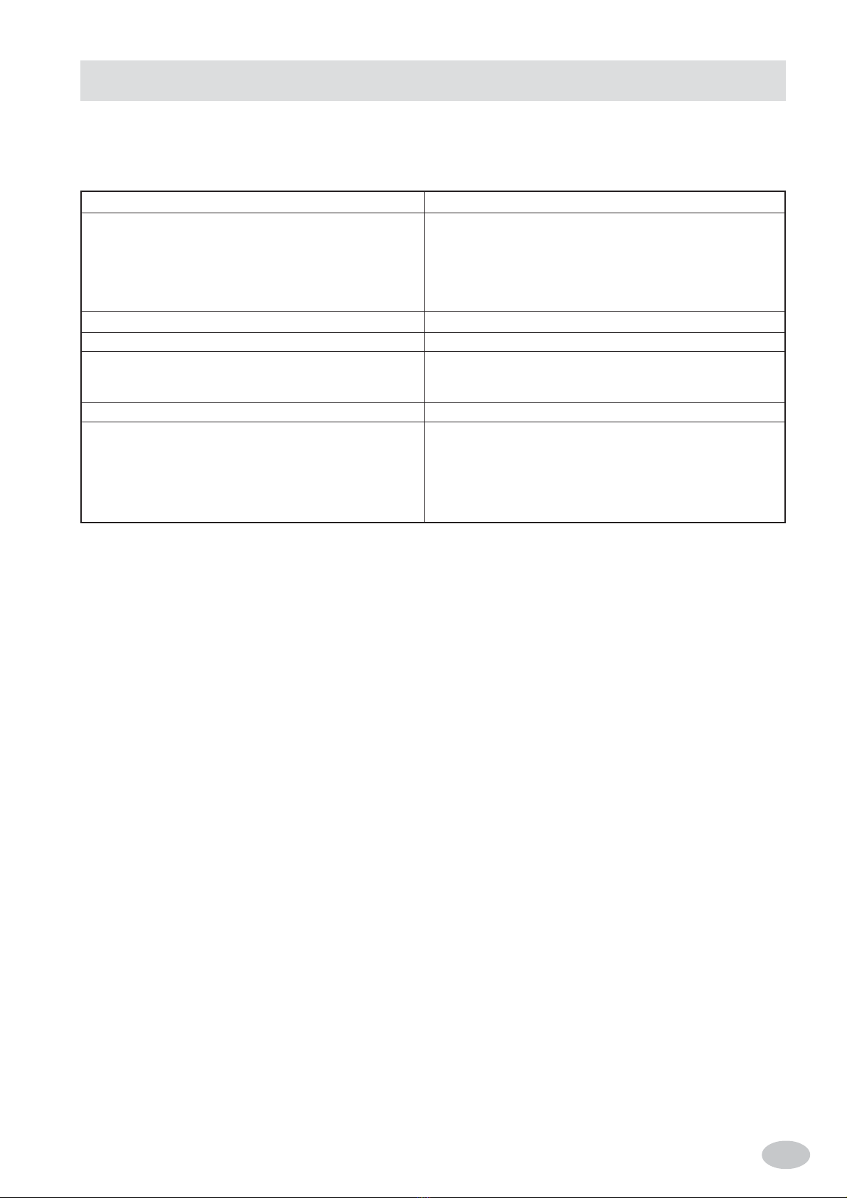
1. Technical data ..................................................................................................................................... 13
1.1 Table I: Technical data gas-fed pasta cooker, Category II (Natural gas and L.P.G.) ........................... 13
1.2 Technical characteristics ..................................................................................................................... 13
2. Installation instructions ...................................................................................................................... 14
2.1 Information about gas-fed pasta cooker series minima ....................................................................... 14
2.2 Installation .......................................................................................................................................... 14
2.2.1 Laws, regulations and technical directives to be complied with ........................................................ 14
2.2.2 Installation place ................................................................................................................................. 15
2.2.3 Positioning .......................................................................................................................................... 15
2.2.4 Assembly of top equipment on counterbasis (side illustration) ........................................................ 15
2.2.5 Water connection ................................................................................................................................. 15
2.2.6 Water drain .......................................................................................................................................... 15
2.3 Gas system connection ........................................................................................................................ 15
2.4 Discharge of exhaust flue products ..................................................................................................... 16
2.4.1 Gas units type a ................................................................................................................................... 16
2.5 How to achieve the nominal thermal capacity.................................................................................... 16
2.5.1 Incoming pressure check (Pe) .............................................................................................................. 16
2.5.2 Nozzle pressure check (Pi) .................................................................................................................. 16
2.5.3 Adjusting the minimum thermal capacity .......................................................................................... 16
2.5.4 Liquid gas operation control............................................................................................................... 16
2.6 Operation control ................................................................................................................................ 16
2.7 Introduction to users ........................................................................................................................... 16
3. Transformation to operate with other gas type ................................................................................... 17
3.1 Replacing the main burners nozzles ................................................................................................... 17
3.2 Replacing the pilot burners nozzles ................................................................................................... 17
4. Replacing important components ....................................................................................................... 17
5. Instructions to users ............................................................................................................................. 18
5.1 Container filling .................................................................................................................................. 18
5.2 Igniting the burners ............................................................................................................................. 18
5.3 Switching off ....................................................................................................................................... 18
5.4 Draining the tub .................................................................................................................................. 18
6. Maintenance and cleaning .................................................................................................................. 18
TABLE II: GAS,PRESSUREAND CLASSES INDIFFERENTCOUNTRIES.AS PER EN437EN 203-1-2 ..... 43
TECHNICAL DATA ............................................................................................................................. 44
SCHEMA D’INSTALLAZIONE .......................................................................................................... 56

- 12 -
GB
- Carefully read the instructions contained in the present booklet as they supply important information
relating to safe installation, use and maintenance.
- Keep this booklet with care, for any further consultation by the various operators.
- Havingremoved the packing,make sure theunit is ingood order andin case ofdoubt, do notuse the unit,but call
onskilled personnel.
- Beforeconnectingthe unit, makesurethe dataappearingon the labelcorrespondto those ofthemain gas supply.
- Thisunit must onlybe destined tothe use it was expresslybuilt for ; anyother usemust be deemedimproper and
thereforedangerous.
- The unit must be used only by a person trained for its operation.
- For any repairs, please call exclusively an authorised technical service centre, and ask for original spare parts
only.
- Non compliance with the above may compromise the unit’s safety.
- Do not wash the unit with direct or high-pressure water jets.
- Do not obstruct openings or draft grids or heat vents.
GENERAL REMARKS
In case of non-compliance with the indications contained in the present manual, both on the user’s part and on the
installing technician’s part, the Manufacturer declines any responsibility, and any possible accident or fault caused by
the above mentioned non-compliances will not be imputable to the Manufacturer.
The Manufacturer declines any responsibility for any imprecisions appearing on the present booklet, ascribable to transcription
or printing errors. Furthermore, the Manufacturer reserves the right to make any modifications to the product deemed useful
or necessary, without prejudicing its essential characteristics.
- 13 - GB
1.2 TECHNICAL CHARACTERISTICS
Stainless steel frame AISI 304, stainless steel panels and base mounted on height-adjustable feet.
-TANK made of stainless steel AISI 304
- GAS HEATING by means of self-stabilising flame burners made of steel, assuring a high heating uniformity . Temperature
thermostatic adjustment with safety valve and thermocouple for the interruption of gas in case of accidental extinguishment
of the pilot burner. Piezoelectric ignition for pilot.
1.1 TABLE I: TECHNICAL DATA GAS-FED PASTA COOKER, CATEGORY II (NATURAL GASAND L.P.G.)
(1) Including the pilot thermal capacity approx. 400 W
MODEL
Dimensions
Width
Depth
Height
TotalHeight
Chimneydischarge diam. Type B11
NetWeight
Chimney
Tankdimensions and No.
Width
Depth
Gasconnection
Nominalthermal capacity
Combustion air / fan
Gasconsumption
L.P.G. G 30/31
NaturalGasH-G 20
NaturalGasL-G 25
Type
mm
mm
mm
mm
Ø mm
kg
kg
mm
mm
“A”
(1) kW
m3/h
(15°C)
g/h
m3/h
m3/h
GC66
A
600
600
290
480
-
35
-
-
510
340
G1/2”
11
20
867/854
1,164
1,35
1. TECHNICAL DATA
- 14 -
GB
2.1 INFORMATIONABOUT GAS-FED PASTA COOKER SERIES MINIMA
This manual applies to our Gas-Fed Pasta Cooker Series Minima, Type A1 Category II (Natural Gas and L.P.G.).
See table 1.1.
The label according to EN437 and EN203-1-2, is located at back and inside.
Example for Italy label:
Category II 2H3÷
Pe = Incoming Pressure
Pi = Nozzle Pressure
SN°Mod.
Pin.N°
Made by
Type
Cat.
Pn (mbar)
II
2HS3B/P
25,25,30/30
G 30
G 31
G 20
G 25.1
REA 16238T4 ITALY
HU
kW
Hz
20,37,50
MK
Installation must be performed by qualified technicians according to the law in force.
See technical date tables : 1.1.
WARNINGS:
Should the unit be installed against a wall, the latter must be heat-resistant to temperatures of 100°C and must be fireproof, or
it has to be placed at a distance of 10 cm.
Before proceeding with the installation, remove the protective plastic film from the relevant parts, eliminating any adhesive
residues with an appropriate cleaning product suitable for stainless steel.
Install the unit in a horizontal position; its correct levelling will be achieved by rotating the adjustable feet.
2. INSTALLATION INSTRUCTIONS
2.2 INSTALLATION
2.2.1 LAWS, REGULATIONS ANDTECHNICAL DIRECTIVES TO BE COMPLIED WITH
The following indications should be observed during installation:
- Accident and fire regulations in force
- Prescriptions by the Gas Supply Company, which should issue an authorisation before installation.
- Instructions for the “Installation of gas equipment”
- Hygienic regulations.
- 15 - GB
2.2.2 INSTALLATION PLACE
- The unit should be installed in adequately ventilated places. (This unit requires a draft of at least 2 cu.m/hr x kW P.T.
(Thermal capacity).
- Install the equipment in compliance with the safety rules applicable in the country where the equipment is installed
2.2.3 POSITIONING
- The various units may be installed individually or together with other units of our range.
- This unit is not suitable for encasing.
- The distance between side walls must be a minimum of 10cm; should the distance be less or the wall or floor material be
flammable, it is essential to use a thermal insulator.
2.2.4 ASSEMBLY OF TOP EQUIPMENT ON
COUNTERBASIS (SIDE ILLUSTRATION)
Unscrew and take away the two frontal foot (P) from the
equipment, which is to be located on the counter, place it
on this so that the 2 back foot (N) fit in the corner of the
base as represented in the picture.
Place the equipment completely and fix it screwing the 2
frontal foot (P) through out the base’s holes for the fixing
of it.
2.2.5 WATER CONNECTION
Maximum water pressure: 4 bar (400 kPa).
In order to carry out a perfect installation, make sure that:
- the device is fed with drinkable water
- the water inlet pipe is connected to the distribution
system through a gate valve that closes when the device
is not operating or when it needs maintenance operations
- between the gate valve and the pasta cooker’s connecting pipe, a mechanical filter has to be installed in order to avoid the
penetration of iron impurities ; after oxidation, they may corrode and damage the container because of oxidation.
- it is recommended (before connecting the last part of the pipe to the pasta cooker coupling) to let some water run in order
to drain the pipe from any possible iron impurity.
2.2.6 WATER DRAIN
Convey the pasta cooker drain pipe (position 1) towards an open-type siphon (position
2) so as to avoid the contact between the drain pipe of the device and the collecting
siphon, in compliance with the hygienic rules applicable in the relevant country.
The drain of the device is to be connected in such a way as to enable the pipe to
withstand a temperature of roughly 100 °C.
2.3 GAS SYSTEM CONNECTION
- The unit should be supplied with gas having the characteristics and the pressure
shown on Table II.
- The gas pressure is measured at the initial pressure outlet with the burner on (see Fig. 1).
- The unit is tested and fitted to operate with natural gas H G20 - 20mbar.
* N.B. Should the supply pressure vary more than +10% of the nominal pressure, it is advisable to install a pressure
regulator ahead of the unit to guarantee the nominal pressure.
- Gas supply connection should be performed by means of metal piping of an appropriate cross section and an approved
shutoff cock should be fitted at source.
- Having connected the gas supply, you should make sure no leaks exist at the joints by checking with bubble soap.

- 16 -
GB
2.4 DISCHARGE OF EXHAUST FLUE PRODUCTS
The units should be installed in premises suitable for the discharge of flue products, which must occur in compliance with the
installation instructions. Our equipment (see Table 1.1 for technical data) is classified as:
2.4.1 GAS UNITS TYPEA1
They are not suitable to be connected to a flue discharge control.
The gas unit should be positioned beneath a draft hood with its system complying with the Regulations. (This unit needs at
least 2cu.m/hr • kW T.C. (Thermal Capacity).
Check kitchen ventilation: it should by complying with the Regulations in force.
2.5 HOW TOACHIEVE THE NOMINAL THERMAL CAPACITY
Check whether the unit is fitted for the gas type, pressure and category corresponding with the main gas supply.
Indication shown on packing and/or the label of the unit.
If the unit is fitted for another gas type or pressure, you need to first effect a change over to the other gas type.
See Table II . for the nozzle, the idle screw (bypass), the pilots nozzles and the nozzle pressure for the main burners.
N.B. The names of nozzles “2H” and “3+” are shown on the left side of Table II.
2H= G20 - 20mbar
3+= G30 29mbar and/or G31 - 37mbar coupled gas and pressure. In our sector, we almost always have to deal with G31 - 37mbar!
Table II shows the types of gas and pressure for all burners and respective nozzles, the X mm distance for the adjustment of
primary air , the idle screw (bypass), the pilot nozzle, the maximum and minimum pressure at nozzle, the maximum and
minimum thermal capacity, and the gas consumption in l/hr (15°C) or in g/hr in the case of L.P.G.
Attention: If the incoming gas’“dynamic” pressure to the unit is lower than the minimum pressure on Table II, connection is
prohibited; furthermore, the fitter should notify the gas Company that the supply pressure is too low.
N.B. Should the pressure vary more to than +10% of the nominal pressure, e.g. for G20 > 22mbar, it is advisable to mount a
pressure regulator ahead of the unit in order to guarantee the nominal pressure.
Should the supply pressure exceed the maximum pressure on Table II, e.g. for G20 > 25mbar, notify the gas Company.
Make sure the inlet and nozzle pressures agrees with the values shown on Table II.
2.5.1 INCOMING PRESSURE CHECK (PE)
Pressure is measured with a manometer 0÷80mbar (precision at least 0.1mbar).
The pressure socket Fig. 5 is located on the G 1/2" gas ramp behind the panel; undo the screw (A) of the pressure socket (B),
attach the silicone rubber to the manometer, ignite the burner and take the incoming “dynamic” pressure.
Fasten the screw (A) back with a gas washer (C), check gas sealing with bubble soap.
2.5.2 NOZZLE PRESSURE CHECK (PI) FIG. 1
The pressure tube (Picture 1) is located on the out-going screw.
The silicone rubber is prepared for high temperatures and should be protected with tin foil to avoid its burning.
2.5.3 ADJUSTING THE MINIMUM THERMAL CAPACITY
The right minimum for thermal capacity is achieved by means of the bypass idle screw completely opened (100%).
2.5.4 LIQUID GAS OPERATION CONTROL
Check whether the fitted nozzles comply with the indications on Table II.
Check whether the incoming pressure complies with the indications on Table II.
Make sure that the L.P.G. gas system has two pressure regulators of suitable capacity and that the evaporation capacity is
sufficient.
See also the publication “Installation Regulations and Characteristics of L.P.G. Systems”.
2.6 OPERATION CONTROL
- Start the unit in accordance with the use instructions Chap. 5.
- Make sure there are no leaks following the local procedures.
- Check the ignition and interignition of the pilot burner and the main burner.
- Make sure the flue gases are discharged regularly.
- Write on a sticker to be glued to the unit label, for what gas and pressure the unit has been calibrated.
2.7 INTRODUCTION TO USERS
Explain the operation and use of the Pasta cooker to its user by consulting the manual, and illustrate any changes.
Leave this instruction manual with the user and explain he/she must consult it for any future reference.

- 17 - GB
The unit should be checked at least twice a year. You must check the burners, the ignition, the interignition, the
maximum and minimum settings.
For any repairs, consult exclusively an authorised assistance centre and ask for original spare parts.
Before carrying out the disassembling of components and their replacement, shut off the gas valve.
Remove the front panel.
Proceed to replace the most important components:
A) Piezoelectric Igniter (on front panel)
- Detach the high-voltage wire from the igniter
- Unscrew the nut with a 27mm-spanner
- Replace the igniter
- Mount everything back by following the reverse order sequence.
B) Pilot spark-plug (Fig. 2 position 5)
- Detach the high-voltage wire
- Unscrew the nut (Fig. 2 position 8) using a 10mm-spanner
- Replace the spark-plug
- Mount everything back by following the reverse order sequence.
C) Thermocouple (Fig. 2 position 4)
We advise you to remove the spark-plug (see position B), since the ceramic part is quite fragile.
- Unscrew the nut (Fig. 2 position 9) using a 10mm-spanner
- Using a 9mm-spanner, unscrew the thermocouple of the safety valve (Fig. 3)
- Mount everything back by following the reverse order.
D) Pilot burner “Targhet” (Fig. 2 position 6)
- Remove the spark-plug (see position B), since the ceramic part is quite fragile.
- Remove the thermocouple by using a 10mm-spanner (Fig. 2 position 4 and 8).
- Remove the gas connection by using a 10mm-spanner (Fig. 3 position 2), being careful not to misplace the nozzle (Fig. 2
position 7).
- Remove the pilot from the burner bracket.
- Change the pilot burner.
- Mount everything back by following the reverse order.
ATTENTION : Tighten the nut firmly (Fig. 2 position 2) and check the gas seal with soap bubbles.
E) Safety Valve knob (Fig. 4)
- Unscrew the gas inlet (5) and outlet (7) connections with a size-19 spanner
- Unscrew the pilot burner inlet (4) with a size-10 spanner
- Unscrew the thermocouple (6) with a size-9 spanner
- Install the new safety valve knob
- Check the idle screw (bypass) (B); it should comply with Table II.
ATTENTION: check the gas sealing with bubble soap.
F) Burner (Fig. 1 position T)
- Disconnect the gas supply pipe (position 0)
- Remove the screws (R) with a spanner of 8 mm.
Now you can replace the burner.
- Mount everything back by following the reverse order.
ATTENTION : Check the gas seal with soap bubbles.
Shut off the gas valve supplying the unit.
3.1 REPLACING THE MAIN BURNERS NOZZLES (FIG. 1)
- Using a size-12 spanner, unscrew nozzle (U) and replace it with the one corresponding to the selected gas, according to the
indications on Table II Ch. 3.4.
3.2 REPLACING THE PILOT BURNERS NOZZLES (FIG. 2)
- Attention : First remove the spark-plug (Fig. 2 position 5) by unscrewing the nut (Fig. 2 position 8) with a 10mm-spanner.
- Unscrew the nut using a 10mm-spanner (Fig. 2 position 2) and remove the pilot nozzle (Fig. 2 pos. 7).
- Exchange the pilot nozzle (Fig. 2 position 7) with one corresponding with the selected gas, in accordance with the
indications of Table II Ch. 3.4.
- Tighten the nut (Fig. 2 position 2) firmly with a 10mm-spanner.
After replacing the nozzles, apply on the existing label the one supplied with the machine indicating the new type of gas.
3. TRANSFORMATION TO OPERATE WITH OTHER GAS TYPE
4. REPLACING IMPORTANT COMPONENTS

- 18 -
GB
Premise
Before operating the unit, thoroughly wash the inside of tub with hot water and detergent., then rinse accurately.
Never use coarse kitchen salt which, on depositing at bottom of tub and being too heavy to be circulating, cannot fully
dissolve. This undissolved salt in the long run may engender, in its contact points, a corrosion condition; we therefore
advise to use fine salt (with a less then 3mm grain) in the tub, and after boiling point. If this is not possible and you only have
large coarse salt, dissolve it first in hot water in a separate container.
5.1 CONTAINER FILLING
- You can fill the container by turning the tap control lever (L, point 2.0.1.) that activates the tap and that lets water through
the dispenser (E, point 2.0.1.).
- Fill the container until you reach the level mark.
- The container is equipped with a drain hole for overflow (O) that prevents water from overcome a pre-set level.
- In order to cook professionally, we recommend to use 10 litres of water per 1 kg of pasta to be cooked.
- The GC66 pasta cooker can contain a maximum of 2.8 kg of pasta.
5.2 IGNITING THE BURNERS
- Open the main gas cock ahead of the unit.
- Turn the knob and turn it to the pilot “ignition” position ( ), then press the knob deeply down.
- Subsequently push the piezoelectric ignition button two or three times, in order to cause a spark to ignite the pilot flame;
you can check through the open door and the peephole. After approx. 20 seconds, release the knob; the pilot burner
should stay on; if this doesn’t happen, then repeat the operation.
- Ignition of the main burner is achieved by turning the knob to the “pilot ignition” position ( ) on maximum ( ).
- To bring the burner to minimum, push down and turn the knob further, to the minimum position ( ).
5.3 SWITCHING OFF
- To switch the main burner off, turn the knob to the “pilot ignition” position ( ).
- To switch the pilot off, to be done only at end of work and with an empty tub, push and turn the knob to the “OFF” position ( ).
- Finally, shut off the main gas cock ahead of the unit.
5.4 DRAINING THE TUB
To drain the tub, open the relevant tap (lever Q): the water will automatically drain off the unit, through the direct drain body
that should be connected to a trap of the open type.
Should drainage occur into a container, use a metallic one, which must be fitted in a stable and safe manner.
-Clean the stainless steel parts daily with soapy lukewarm water, then rinse well and dry thoroughly.
- Absolutely avoid to clean the stainless steel with common steel-wool, or common steel brushes and scrapers, as they may
discard ferrous particles which, on depositing, cause rust spots. You may, if you like, use stainless steel-wool passed on
following the butter-finish direction.
- Should the unit remain unused for long periods, heavily rub all the steel surfaces with a cloth slightly wetted with vaseline
oil, in order to cover them with a protective film. Periodically ventilate the premises.
- Absolutely avoid continuous or intermittent contact with ferrous material, in order not to cause galvanic corrosion
reactions. Therefore ladles, turners, spoons, skimmers, etc. should be made of stainless steel.
- Once the tub is drained, thoroughly wash it so as to remove any incrustations, preferably using nylon brushes.
ATTENTION
Should the unit remain inactive for long periods, do not leave water in the container.
The manufacturer shall not be liable for damages caused by non-compliance with the above mentioned maintenance
instructions.
5. INSTRUCTIONS TO USERS
6. MAINTENANCE AND CLEANING

- 19 - FR
CHAPITRE DESCRIPTION PAGE
Instructions generales .......................................................................................................................... 20
1. Donnees techniques ............................................................................................................................ 21
1.1 Tableau I: Donnees techniques cuiseur de pates au gaz Cat. II (Gaz Méthane e G.P.L.) .................... 21
1.2 Caracteristiques techniques ................................................................................................................ 21
2. Instruction puor l’installation ............................................................................................................. 22
2.1 Plaquette d’identification des cuiseur de pates au gaz serie Minima ................................................. 22
2.2 Installation .......................................................................................................................................... 22
2.2.1 Legislation a respecter ........................................................................................................................ 22
2.2.2 Lieu d’installation ............................................................................................................................... 22
2.2.3 Mise en place....................................................................................................................................... 23
2.2.4 Montage de l’équipément à top sur armoire ..................................................................................... 23
2.2.5 Raccordement eau ............................................................................................................................... 23
2.3 Raccordement a l’installation du gaz ................................................................................................. 23
2.4 Evacuation des produits de combustion par une hotte d’aspiration .................................................. 23
2.4.1 Appareil de type A1 ............................................................................................................................ 23
2.5 Comment obtenir un debit thermique nominal .................................................................................. 24
2.5.1 Controle de la pression en amont (Pe) ................................................................................................ 24
2.5.2 Controle de la pression au gicleur (Pi) ................................................................................................ 24
2.5.3 Reglage du debit thermique minimum ............................................................................................... 24
2.5.4 Controle pour le fonctionnement au gaz liquide ................................................................................ 24
2.6 Controle du fonctionnement ............................................................................................................... 24
2.7 Informations de l’usager ...................................................................................................................... 24
3. Convertion du type de gaz .................................................................................................................. 25
3.1 Changement des gicleurs des bruleurs principals ............................................................................... 25
3.2 Changement des gicleurs des bruleurs de la veilleuse........................................................................ 25
4. Changement des composants plus importants .................................................................................... 25
5. Instructions pour l’utilisateur .............................................................................................................. 25
5.1 Remplissage de la cuve ....................................................................................................................... 26
5.2 Allumage des bruleurs ......................................................................................................................... 26
5.3 Extinction............................................................................................................................................ 26
5.4 Vidage du bac ...................................................................................................................................... 26
6. Entretien et nettoyage ......................................................................................................................... 26
TABELLE II: PRESSIONS ET CATÉGORIES DANS LES DIFFÉRENTS PAYS. SELON LES NORMES
EN 437 - EN 203-1-2-GAS .................................................................................................................. 43
DONNEES TECNIQUES ..................................................................................................................... 44
SCHEMA D’INSTALLATION ............................................................................................................. 56
INDEX

- 20 -
FR
- Lisez attentivement les instructions contenues dans cette notice car elles fournissent d’importantes
indications concernant la sécurité d’installation, d’emploi et d’entretien.
- Rangez soigneusement cette notice dans un endroit accessible et adapté à de futures consultations.
- Après avoir déballé l’appareil, contrôlez-en l’intégrité. En cas de doute ne l’utilisez pas et adressez-vous à un
personnelqualifié.
- Avantdebrancherl’appareil,assurez-vousquelesinformationsreportéessurlaplaquettesignalétiquecorrespondent
à celles du réseau de distribution du gaz.
- Cet appareil n’est destiné qu’à l’usage pour lequel il a été expressément conçu. Tout autre usage est considéré
impropreet donc dangereux.
- L’appareilne doit êtreutiliséque pasunepersonne formée àsonusage et ayantprisconnaissance du contenude
cette notice.
- Pourlesréparationsadressez-vous seulement à un centredeserviceaprès-venteagréé par le Fabricant etexigez
despièces de rechange d’origine.
- Le non respect de ces indications peut compromettre la sécurité de l’appareil.
- Ne dirigez jamais de jets d’eau à haute pression sur l’appareil pour le laver.
- N’obstruezjamais lesouvertures ou les fentes d’aspirationou d’évacuation de la chaleur.
INSTRUCTIONS GENERALES
En cas de non respect des instructions contenues dans cette notice, aussi bien de la part de l’usager que de l’installateur,
le Fabricant décline toute responsabilité en cas de dégâts à des personnes ou à des biens dérivants de ce non respect.
Le Fabricant décline toute responsabilité sur les conséquences imputables à d’éventuelles inexactitudes dues à des erreurs
de transcription ou d’impression. Le Fabricant se réserve aussi le droit d’apporter toutes les modifications qu’il retiendra
utiles ou nécessaires sur les produits sans en altérer les caractéristiques principales.
Table of contents
Languages:
Popular Cooker manuals by other brands


Falcon
Falcon 900 DL Induction Users guide & installation and servicing instructions

Falcon
Falcon Toledo TXT110DFSSEU Instructions for use and installation

FALMEC
FALMEC Quantum Pro Easy Instruction booklet

Parkinson Cowan
Parkinson Cowan CSIG 317 installation instructions

Bertazzoni
Bertazzoni AMD6C61BX Installation, maintenance and use instructions

MPM
MPM MKE-01M manual