EVAKCOOL DOWN UNDER Series User manual

SERVICE
MANUAL
FOR MODELS
DU95-DZ
DU75-DZ
DOWN UNDER SERIES


3
DOWN UNDER SERIES
This Service Manual is for service agents only, if this fridge is repaired
by a non-authorised agent the warranty may become void. This
manual outlines the specifications, functions, and fault findings for
the Down Under 75L & 95L Dual Zone Fridge Freezers.
Please read this manual carefully to ensure the correct methods are
taken to diagnose and service these products.
If you require more information, please contact
warranty@evakool.com or 1300 385 665.
Contents
1 Electronic Control Overview ............................................................................. 4
2 Spare Parts Classification & Service Instructions ......................................... 7
3 Product Specifications ...................................................................................... 15
4 Basic Fault Finding ............................................................................................. 18
5 Product Drawings . . . . . . . . . . . . . . . . . . . . . . . . . . . . . . . . . . . . . . . . . . . . . . . . . . . . . . . . . . . . . . . . . . . . . . . . . . . . . . . . . . . . . . . . . . . . . . . . 23
6 Exploded View . . . . . . . . . . . . . . . . . . . . . . . . . . . . . . . . . . . . . . . . . . . . . . . . . . . . . . . . . . . . . . . . . . . . . . . . . . . . . . . . . . . . . . . . . . . . . . . . . . . . . . 26

1. Electronic Control Overview
SCOPE OF FUNCTION:
• ON/OFF: Switches refrigerator ON/OFF when button is pressed for one to two second.
• Set Button: Selects input mode:
- Set temperature
- Set battery protection
- Set Max or Eco mode
• Up and Down Arrows: Press once to increase or decrease values.
• Display
- Temperature
- Error Message
- Voltage Usage Display
- Celsius (°C)
- Battery voltage
- MAX or ECO Mode
- Bin 1 and/or Bin 2
DOWN UNDER SERIES
4
LED Control Panel LED Display
On/O
Button
+/- Buttons
SET
Button
Display
ROOM 2 - Smaller Bin
Automatically set to Celsius
Battery Protection
Mode
Error message
will display here
Temperature
Max or Eco Mode
ROOM 1 - Larger Bin

SETTING THE TEMPERATURE:
Important: The temperatures displayed are only an indication of the average temperatures
may be inside the cabinet. *It is normal for the display temperature to vary +/- 5°C from the
set point when the fridge cycles.
• Hold button for 3 seconds to switch on refrigerator.
• Press button once, Room 1’s temperature will flash (large bin).
• Use the or arrows to increase or decrease the temperature to the desired
setting. The selected temperature appears in the display for a few seconds and will be
applied automatically, the display flashes several times before it returns to the current
temperature.
• Press the button twice to access Room 2’s (smaller/stepped bin) temperature display.
• Use the or the arrows to increase or decrease the temperature to the desired
setting. The selected temperature appears in the display for a few seconds and will be
applied automatically, the display flashes several times before it returns to the current
temperature.
SETTING COMPRESSOR SPEED:
• Press button three times, either ECO or MAX will be displayed.
• Use the and arrows to change between ECO and MAX. The display flashes several
times and will then automatically apply the desired setting.
SETTING BATTERY PROTECTION:
• Press the button four times, the L, M or H will display on the screen.
• Use the and arrows to change between Low, Medium and High settings. The
display flashes several times and will then automatically apply the desired setting.
Battery Monitor Mode L M H
Switch-o voltage at 12V 10.1V 10.5V 11.1V
Restart voltage at 12V 10.9V 11.4V 12.4V
Switch-o voltage at 24V 21.5V 22.3V 24.3V
Restart voltage at 24V 22.7V 23.7V 25.7V
DOWN UNDER SERIES
5

DOWN UNDER SERIES
6
SELECTING ONLY ONE BIN:
If you only require cooling for a small amount of product, you can switch OFF either side
and run only one side.
• Press and hold the arrow for 3 seconds this will turn OFF Room 1 (large bin). Reverse
the procedure to turn back ON.
• Press and hold the arrow for 3 seconds this will turn OFF Room 2 (small/stepped bin).
Reverse the procedure to turn back ON.
SUB MENU:
For temperature display oset and Celsius to Fahrenheit.
Changing Oset: With the fridge plugged into a power source and in the OFF position
press and hold the button for 3 seconds, F1 will display, use the button to scroll
through menu.
Function Setting Temp Range Default
F1 Setting Temp > -6°C -10°C ~ +10 °C -2°C
F2 -7°C >Setting Temp > -12°C -10°C ~ +10 °C -4°C
F3 Setting Temp < -13°C -10°C ~ +10 °C -6°C
F1: Setting the temperature as 0 degree, put the sensor in the middle of cabinet, check
the temperature dierence with the display temperature then choose F1 oset.
F2: Setting the temperature as -10 degree, put the sensor in the middle of cabinet, check
the temperature dierence with the display temperature then choose F2 oset.
F3: Setting the temperature as -18 degree, put the sensor in the middle of cabinet, check
the temperature dierence with the display temperature then choose F3 oset.
Changing Celsius to Fahrenheit: With the fridge plugged into a power source and in the
OFF position press and hold the button for 3 seconds, F1 will display, use the button
to scroll through till CF appears, then use and buttons to change from Celsius to
Fahrenheit. Leave the control panel and aer 5 seconds it will return to the main screen
with changes installed.

DOWN UNDER SERIES
7
Supply Power
Solenoid
LED (Small Bin)
LED (Large Bin)
Fan
Main Harness
Emergency Switch
(not used)
Thermistor (Small)
Thermistor (Large)
2. Spare Parts Classification & Service Instructions
MAIN PCB: (COMP-PBC2.5)
FAULT CODES:
The electronics and compressor are designed and built with its own fault finding system,
which will be displayed on the Main PCB, below is a table of codes relating to faults
displayed.
CODE F AU LT
E1 Battery Protection Failure
E2 Fan Failure
E3 Compressor Start Fault
E4 Min/Max Speed Fault
E5 Overheating Protection
E6 NTC Fault
LL NTC Unplugged
NTC Negative Temperature Coeicient = Thermistor

REMOVAL OF PCB:
To remove the main PCB (DO NOT peel o the sticker), firstly undo the 6 x Phillip head
screws holding the display mounting plate (Part No: HOUSE-DISP-7) to the cabinet. Undo
the 5 x screws holding the PCB to the mounting plate.
Important: Before disconnecting the wires from the PCB, make a note or take a photo of
which wires go to which sockets, remove the wires from the PCB, reverse the procedure to
re-install the new PCB.
FAN: D12BM-12 120mm x 120mm x 25mm (Part No: FAN-C)
We use the above mentioned fan, for the reliability and longevity of a ball bearing fan. The
air flow is good at 72 CFM and is an acceptable noise level for the customer.
REPLACEMENT: (Part No: FAN-C)
To replace the fan if faulty, remove the 10 screws securing the engine bay cover, remove
cover. The fan will be located on the right hand side of the engine bay, undo the 4 x metal
thread screws holding the fan on, trace the wires back to the main PCB unclip old fan from
PCB and fit new (see section on PCB for fan location on page 7), re-attach new fan, (sticker
side facing out), so the air is drawn through the condenser and expelled out through the
engine bay cover vent.
8
DOWN UNDER SERIES
Remove the five screws holding the main display
PCB to the display plate.
Remove the six screws attaching the
display mounting plate.

9
SOLENOID: Sanhua KMV432. 12 Volt 9.4W solenoid. (Part No: SOLENOID-A)
These fridges have 2 separate refrigeration systems and one compressor. The solenoid is
used to direct liquid refrigerant at the drier to the circuit that requires refrigeration. The
electronics sense when either the small or large bin needs cooling and sends a 12 Volt
pulse to the solenoid, either a positive or negative pulse is required to change from one
side to another.
To Test: To see if the solenoid is switching, first turn the refrigerator on, Room 2 (small bin)
will start to refrigerate, feel where the capillary enters the evaporator plate (image 4 & 5).
When it starts to feed, switch OFF that bin (see page 5), the solenoid will then switch over
to the other side, feel where the capillary enters the evaporator if it starts to feed you know
that the solenoid is switching and capillaries are clear, so the issue may be in the PCB
controlling the solenoid.
Warning: Before removing the old solenoid carefully mark or identify the capillaries so
they go back into the correct sides of the solenoid, failing to do so will result in erratic
temperature fluctuations and incorrect temperatures in both sides. Wrap the body of the
solenoid in wet rags before welding, failing to do so will melt the internals and stop the valve
from switching.
To Replace: Once identified, with the use of a capillary cutters, cut o both capillaries,
open the top cap and remove the wires small terminal (red) and large terminal (black),
un-sweat the drier from the condenser as it needs to be replaced, now the system is
opened (image 1). To install a new solenoid, insert the capillaries into their correct tubes
and push in all the way (there is a small dimple in the receiving copper tube to ensure
the capillary cannot be pushed in to far). Unpack the new drier and insert the large pipe
on the solenoid into the exit opening of the drier then insert the discharge tube from the
condenser into the entry opening of the drier.
DOWN UNDER SERIES
Image 1 Image 2 Image 3
Image 4 Image 5

10
DOWN UNDER SERIES
FILTER DRIER: (Part No. DRIER-SOLENOID-1)
We strongly advise to only use Evakool filter driers. Copper spun driers are made with
spring loaded sieves to prevent the desiccant from breaking down and blocking capillaries
(the unit is subject to heavy knocks and vibration as a portable appliance).
COMPRESSOR:
In our range of Australian built Evakool fridges we only use and recommend SECOP
compressors, originally designed and built by Danfoss in Germany, they are the industries
leader in design and performance in 12 Volt compressors.
These compressors are multi speed allowing for Evakool fridges to be programmed to ‘so
start’ to reduce high starting current, ultimately reducing power consumption. Every time
the fridge starts the compressor is programmed to start at its slowest speed (2000 RPM).
Once the fridge is up to speed, the system is primed for 2 minutes and it will then set to the
selected speed (Max or Eco).
Secop compressors have a fault finding system built into the electronic module, listed
below are the codes and their faults.
LED
FLASHES ERROR TYPE
5Thermal cut-out or electronic unit: If the refrigeration system has been too
heavily loaded, or if the ambient temperature is high, the unit will run too hot.
4Minimum Motor Speed Error: If the refrigeration system is too heavily loaded,
the motor cannot maintain minimum speed at approximately 1,850 rpm.
3Motor Start Error: The rotor is blocked if the dierential pressure in the
system is too high (>5 bar).
2Fan over-current cut-out: The fan loads the electronic unit with more than
0.5A avg.
1 Battery protection cut-out: The voltage is outside the cut-out setting.

11
DOWN UNDER SERIES
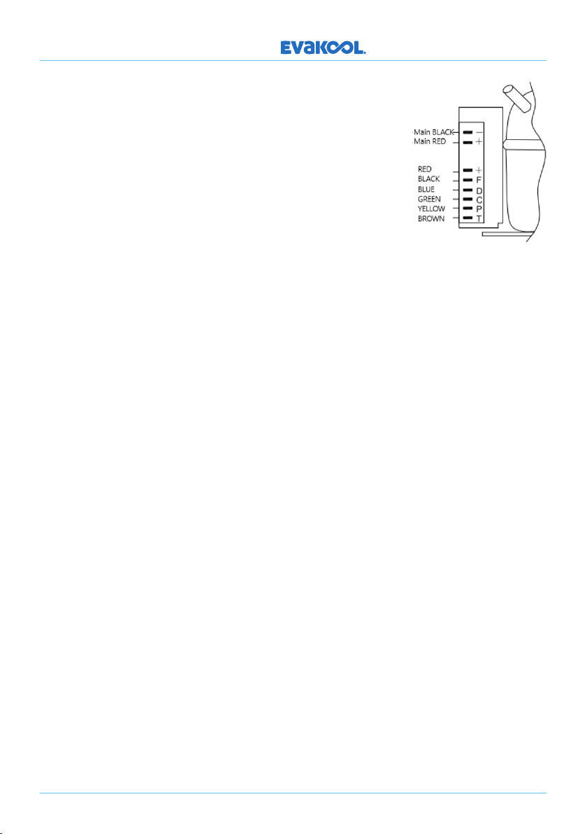
Wiring harness to the Secop Module, see below the color codes to each terminal.
For more information: https://www.portable-box-compressor.com/userdata/pdfs/secop_
portable_box_compressors_10-2015_desb100c102.pdf.
NTC - THERMISTOR: (Part No: NTC-DU)
We have made the thermistors, in these fridges with a removable head for easier
replacement and diagnosis.
Removal: There are 2 x thermistors one in each bin located behind a small plastic vented
hood (Part No. NTC-HOOD-DU). With a small flat blade screwdriver, lever the housing cover
out from the top (see photo below), remove the thermistor head from the housing and
disconnect at the plug. Install the new thermistor then re-install the hood cover.
12
DOWN UNDER SERIES
TESTING:
Test the resistance of the thermistor against the table below, if outside these parameters
replace thermistor.
Temperature Resistance K Ohms
30°C 8.8K Ohms
25°C 9.8K Ohms
20°C 11.8K Ohms
15°C 13.9K Ohms
10°C 16.8K Ohms
5°C 20.6K Ohms
0°C 25.6K Ohms
-5°C 32K Ohms
-10°C 40.7K Ohms
-15°C 51.9K Ohms
-20°C 66.4K Ohms
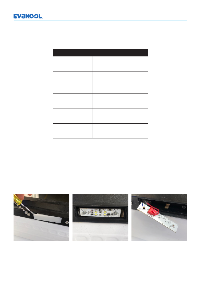
LED LIGHT: (Part No. LED-DU)
There are 2 x LED lights in the fridge, one in Room 1 and one in Room 2, these lights are
constantly on as long as there is power supplied to the unit, (even in the o position).
Removal: Lever o the LED cover (Part No: LED-CVR-DU) with a small flat blade screwdriver
as per the photo, un-screw the 2 x small Phillip head screws, remove the PCB, un-plug from
connector and replace with new PCB, reverse the procedure to install.
13
DOWN UNDER SERIES
WIRING:
Wiring harnesses in the fridge have been extended, to allow
the display panel to be changed from the le hand side of the
fridge to the right hand side of the fridge. This is for when the
cabinet is to be converted from a right hand motor to a le
hand motor. All connections and wiring are color coded, see
section Main PCB (page 7) for connection locations for wires
to the main PCB. See the illustration here for wire colors and
connections to the compressor module.
CONVERTING THE LIDS AND ELECTRONICS FROM RIGHT TO LEFT:
The cabinet can be converted to open from the opposite side. This is a simple process and
takes approximately 30 minutes to complete.
Tools Required:
• Philips head screwdriver
• 2.5mm Allen key
CONTROL BOARD:
• Remove the screws from the control PCB and the vent shaped like the control PCB on
the opposite side of the cabinet.
• Remove the back cover on the engine bay.
• Re-route the wiring and PCB through to the opposite side, making sure no wires are
unplugged in the process.
• Re-attach the control PCB and vent in their new positions.
LIDS:
• Remove the 4 x black hex head screws holding on the panel with the infinity logo (image
4), this will expose the holes for the hinge screws.
• Open the lids and remove the 2 x screws holding the lid chain to the cabinet, located
next to the LED light (image 1). Once the chain is removed, re-install those screws back
into the holes.
• Remove the screws on all 4 hinges (image 3), (bottom sections of the hinge only) leave
hinges attached to the lids.
• Flip lid over to the other side and re-attach screws to the bottoms of the hinges.
Note: Use only a handheld screwdriver not a cordless drill.
This will reduce the chances of cross threading the screws, lightly fit every screw before
tightening o the lids, make sure they are straight (image 4).

DOWN UNDER SERIES
14
• Fit black panel with infinity logo to the front of the cabinet with black hex head screws,
again lightly fit the screws so that the latch screws will line up. Once the latch is fitted,
align the black panel so that it is level with the top of the cabinet and tighten screws,
then align the latches so they are straight and tighten screws.
• Remove the screw beside the LED light and attach chain, replace the screw.
Important: Room 1 (Large bin) and Room 2 (Small bin).
When the lids are changed over from standard the bins will be opposite to the display, BUT
the display is marked ‘Room 1’ and ‘Room 2’ and the baskets in each compartment are
stickered to the corresponding ‘Rooms’ (image 1 and 2).
Image 1 Image 2
Image 3 Image 4 Image 5

DOWN UNDER SERIES
15
3. Product Specifications
Model No. DU75-DZ DU95-DZ
Gas Charge 60 Grams R134a 70 Grams R134a
New Weight 30kg 33kg
Dimensions (L*W*H) 895.7 x 473.8 x 530 966.3 x 575 x 470
Sound 45dB 45dB
Temp Range +10°C to -18°C +10°C to -18°C
Capacity 75 Litre 95 Litre
Power Supply DC12/24 DC12/24
Rated Power Output 65 Watts 65 Watts
Foam Thickness 50mm 50mm
Climate Class T T
POWER CONSUMPTION:
The engineering of this refrigeration system was done in-house here at Evakool, the system
is very well balanced incorporating extremely eicient rollbond evaporators with an air
cooled copper and aluminum finned condenser and the right amount of insulation to
give perfect cooling and maximum literage in the fridge compartments. We are extremely
happy with the performance of the refrigerator with all of our Australian made fridges
being true tropical rated.
DU75 Down Under 75 Litre - Climate Class ‘T’ Rated
Ambient
Temperature Speed Voltage Fridge
Temp Set
Freezer
Temp Set
Amps consumed
per hour
24°C ECO 12.8 Volts 2°C -16°C 1.45
32°C ECO 12.8 Volts 2°C -16°C 1.99
38°C ECO 12.8 Volts 2°C -16°C 2.65
43°C ECO 12.8 Volts 2°C -16°C 3.16
24°C MAX 12.8 Volts 2°C -16°C 1.51
32°C MAX 12.8 Volts 2°C -16°C 2.1
38°C MAX 12.8 Volts 2°C -16°C 2.8
43°C MAX 12.8 Volts 2°C -16°C 3.58

DOWN UNDER SERIES
16
24°C ECO 12.8 Volts 2°C 2°C 0.68
32°C ECO 12.8 Volts 2°C 2°C 1.05
38°C ECO 12.8 Volts 2°C 2°C 1.68
43°C ECO 12.8 Volts 2°C 2°C 2.09
24°C MAX 12.8 Volts -16°C -16°C 1.77
32°C MAX 12.8 Volts -16°C -16°C 2.44
38°C MAX 12.8 Volts -16°C -16°C 3.05
43°C MAX 12.8 Volts -16°C -16°C 3.75
Test Conditions: 12.8V DC. Controlled test room. Set ambient temperatures. 24hr test period.
Fridge remained closed. No product inside. Fridge 2°C. Freezer -16°C.
DU95 Down Under 95 Litre - Climate Class ‘T’ Rated
Ambient
Temperature Speed Voltage Fridge
Temp Set
Freezer
Temp Set
Amps consumed
per hour
24°C ECO 12.8 Volts 2°C -16°C 1.5
32°C ECO 12.8 Volts 2°C -16°C 2.09
38°C ECO 12.8 Volts 2°C -16°C 2.71
43°C ECO 12.8 Volts 2°C -16°C 3.5
24°C MAX 12.8 Volts 2°C -16°C 1.65
32°C MAX 12.8 Volts 2°C -16°C 2.1
38°C MAX 12.8 Volts 2°C -16°C 2.75
43°C MAX 12.8 Volts 2°C -16°C 3.48
24°C ECO 12.8 Volts 2°C 2°C 0.85
32°C ECO 12.8 Volts 2°C 2°C 1.19
38°C ECO 12.8 Volts 2°C 2°C 1.16
43°C ECO 12.8 Volts 2°C 2°C 2.16
24°C MAX 12.8 Volts 2°C 2°C 0.89
32°C MAX 12.8 Volts 2°C 2°C 1.28
38°C MAX 12.8 Volts 2°C 2°C 1.74
43°C MAX 12.8 Volts -2°C 2°C 2.3
24°C MAX 12.8 Volts -16°C -16°C 1.97

DOWN UNDER SERIES
17
32°C MAX 12.8 Volts -16°C -16°C 2.5
38°C MAX 12.8 Volts -16°C -16°C 3.34
43°C MAX 12.8 Volts -16°C -16°C 4.27
Test Conditions: 12.8V DC. Controlled test room. Set ambient temperatures. 24hr test period.
Fridge remained closed. No product inside. Fridge 2°C. Freezer -16°C.
What is Climate Class?
Refrigerators are designed to work under certain climate conditions which are rated by
climate classes. It indicates the minimum and maximum temperature limits, within which
the refrigerators are able to operate properly.
All fridges and freezers are rated with 4 main climate classes as below:
1. SN (Subnormal) suitable for use under ambient temperature range of 10°C-32°C
(50°F-90°F).
2. N (Normal) suitable for use under ambient temperature range of 16°C-32°C (61°F-90°F).
3. ST (Subtropical) suitable for use under ambient temperature range of 18°C-38°C
(64°F-100°F).
4. SN (Tropical) suitable for use under ambient temperature range of 18°C-43°C
(64°F-109°F).
Note: These abbreviations are conventional because they are regulated by international
standards (IEC Clauses) for refrigeration equipment and do not depend on a maker or a
country of production.
Some fridges and freezers are developed with combined climate classes to allow the
operation within a wider temperature range, like some outdoor locations or special
regions. For example:
1. N - ST suitable to operate under temperatures ranging from 16°C - 38°C (61°F-100°F).
2. SN - T suitable to operate under temperatures ranging from 10°C - 43°C (50°F-109°F).
Why is it so important to choose a fridge with appropriate Climate Class?
Not all refrigerating appliances are suitable for all ambient temperature ranges. Very few
people would check or even know about the characteristics of climate classes, but it is
really important to think twice before the purchase. Here are some reasons:
• If a fridge keeps running under the climate conditions that it is not intended for, it will
consume much more energy to reach the required inside temperature.
• The fridge will not cool the inside product suiciently, which will lead to excessive
condensation.
• The viscosity of the oil in the compressor will increase if it works at ambient temperature
under 10°C (50°F), and with the loss of fluidity, the compressor could be damaged easily.
• The lifespan of the refrigerators will decrease significantly.

18
DOWN UNDER SERIES
4. Basic Fault Finding
Compressor running but not cooling: Probable cause - gas leak.
• Check if there is any heat in the discharge line and condenser, if there is no heat present
there is a likelihood that no gas is in the system.
• Fit gauges to access port and check if there is any refrigerant in the system if there is no
gas present.
• Fill the system with nitrogen and bubble test all the joints in the engine bay, if nothing is
detected in the engine bay STOP TESTING as the leak will be internal and not repairable.
DO NOT spend any more time on the job. Re-seal pipe aer removing access valve.
Important: Do not exceed 100psi or 690Kpa pressure of nitrogen, doing so will destroy the
rollbond evaporators which are not replaceable.
Compressor running but only feeding one side: Probable cause - Solenoid, Main PCB or
capillary blockage.
• Firstly check if the solenoid is switching, turn the refrigerator on, Room 2 (small bin) will
start to refrigerate, feel where the capillary enters the evaporator plate. When it starts
to feed, switch OFF that bin (see page 5) the solenoid will then switch over to the other
side, feel where the capillary enters the evaporator if it starts to feed you know that the
solenoid is switching and capillaries are clear, so the issue may be in the PCB controlling
the solenoid.
• Blocked capillary: we find that capillary blockages are rarer than the 2 described
symptoms above, the drier used is a wide mouth drier so a blockage will not occur there,
the capillaries are pressed into the evaporators and cannot be replaced, so we advise to
stop work on the unit and contact EVAKOOL for further instructions.
Note: Normally where there is a restriction, be it in a drier or capillary, there will be cold and
condensation present as the refrigerant will be expanding at that point.
Compressor running but not
achieving temperature: Probable
cause - Fan has stopped or condenser
is blocked with flu.
• Remove the back cover and check
if fan has stopped or if the fan is still
running.
• Check the condenser to see if
blocked. To do this, turn o fridge,
stand fridge on its end to access
the base, there is a small inspection

DOWN UNDER SERIES
19
panel (see photo), remove panel and inspect the back section of the condenser. If
blocked, remove the fan and blow compressed air from the front of the condenser to
remove flu build up. Replace inspection plate, and test.
Display not showing the right temperature: Probable cause - Thermistor or Main PCB.
• Test thermistor (see page 11) or replace with a new thermistor.
• If the thermistor is OK then the main PCB may need recalibrating, see section SUB MENU
(page 5) for changing display oset.
• If the above doesn’t work, then a new PCB is required.
• If the cabinet has been changed from right hand motor to le hand motor. The customer
might be matching the temperature indicated to the wrong bin (see page 13).
Important: Room 1 (Large bin) and Room 2 (Small bin).
Note: The displayed temperature is only an indication of what the average temperature may
be inside.
E1 Battery protection cut out OR low voltage failure: Probable cause - faulty
component, bad wiring, wrong battery protection setting or flat/faulty battery.
Please Note: Most E1’s are a consumer error not a manufacturing fault and therefore
not covered under warranty (if fault is not found). Refer customer to the manual for
troubleshooting or to call EvaKool.
• With the use of a multimeter start at the source, measure the voltage at the battery to
determine if the battery is flat or not.
• Make sure that the battery protection mode is set on LOW and check the cutout voltage
in the table (page 5).
• Test with multimeter the various components in the cabinet e.g., plug, circuit breaker
etc.
From a service and warranty point of view, the circuit breakers can fail, so make sure this
component is tested.
Handy Hint: Where there is a drop in voltage there is HEAT so feel the components and
visually check for signs of heat; burning, black terminal covers, tainted metal on connectors
etc.
Important: These tests must be done under load (with compressor running), there will be no
voltage drop if the system is not under load.
Note: The cutout voltage is measured at the Secop control module. As a rule of thumb there
will be approximately 0.5 to 0.8 Volt of losses through the wiring and connectors and circuit
breaker inside the unit, this does not include the losses in the customers wiring set-up.

Example: The unit is set on high battery protection, which is 11.1 V cutout at the
compressor, with losses in the fridge (wiring, connections, circuit breaker) of 0.8 Volts,
this is now showing the fridge cutting out at 11.9 Volts at the battery. Now if we include
the lead we supply, the connection in the customers car and the 5 to 6 metres of cable
from the secondary battery to the fridge this could equate to another 1 to 2 Volts of losses
between the battery and the compressor module, NOW we would measure around 12.9 or
13.9 at the battery and the fridge is cutting out.
These figures are conservative standard resting 12 V battery charge:
• 12.8 volts = 100%
• 12.5 volts = 70%
• 12.3 volts = 50%
• 11.4 volts = 20%
At the Battery: 12.8 Volts minus 1.5 Volts for customers wiring and connections.
At the Anderson connector on the fridge: 11.3 Volts minus 0.8 Volts of losses inside the
cabinet.
At the Secop module on compressor: 10.5Volts
You can see in this example that the fridge will not start at all in High or Medium battery
monitor mode.
Battery Monitor Mode L M H
Switch-o voltage at 12V 10.1V 10.5V 11.1V
Restart voltage at 12V 10.9V 11.4V 12.4V
Switch-o voltage at 24V 21.5V 22.3V 24.3V
Restart voltage at 24V 22.7V 23.7V 25.7V
It also shows the importance of correct wiring for vehicles, bigger is better and reduces the
number of connections between the battery and the fridge.
Cable Thickness (Area) 12V Max Cable Length 24V Max Cable Length
(mm2) AWG (m) () (m) ()
2.5 13 2.5 8 5 16
4 11 4 13 8 26
6 9 6 20 12 39
10 7 10 33 20 66
DOWN UNDER SERIES
20
This manual suits for next models
2
Table of contents


