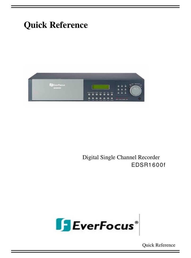
EverFocus EDR810M User manual

INSTRUCTION MANUAL
Digital Eight Channel Recorder
About this manual
Before installing and using this unit, please read this Manual carefully.
Be sure to keep it handy for later reference.
V 1.0
EDR810H/810M/
410H/410M
Date: Aug. 29th 2005

WARNING
TO REDUCE RISK OF FIRE OR ELECTRIC SHOCK,
DO NOT EXPOSE THIS APPLIANCE TO RAIN OR MOISTURE.
CAUTION
DO NOT REMOVE COVER. NO USER SERVICEABLE PARTS INSIDE.
REFER SERVICING TO QUALIFIED SERVICE PERSONNEL.
Note:
This equipment has been tested and found to comply with the limits for a Class A digital device,
The changes or modifications not expressly approved by the party responsible for compliance
could void the user's authority to operate the equipment.
Notice:
The information in this manual was current when published. The manufacturer
reserves the right to revise and improve its products. All specifications are
therefore subject to change without notice.
Safety Warning
Note:
This is a class A product. In a domestic environment this product may cause radio interference
In which case the user may be required to take adequate measures.
2

Refer all work related to the installation of this product to qualified service
personnel or system installers.
Do not block the ventilation opening or slots on the cover.
Do not drop metallic parts through slots.This could permanently damage
the appliance. Turn the power off immediately and contact qualified service
personnel for service.
Do not attempt to disassemble the appliance.To prevent electric shock,
do not remove screws or covers. There are no user-serviceable parts
inside. Contact qualified service personnel for maintenance. Handle the
appliance with care. Do not strike or shake, as this may damage the
appliance.
Do not expose the appliance to water or moisture, nor try to operate it in
wet areas. Do take immediate action if the appliance becomes wet.
Turn the power off and refer servicing to qualified service personnel.
Moisture may damage the appliance and also cause electric shock.
Do not use strong or abrasive detergents when cleaning the appliance
body. Use a dry cloth to clean the appliance when it is dirty. When the
dirt is hard to remove, use a mild detergent and wipe gently.
Do not overload outlets and extension cords as this may result in a risk of
fire or electric shock.
Do not operate the appliance beyond its specified temperature, humidity
or power source ratings. Do not use the appliance in an extreme
environment where high temperature or high humidity exists. Use the
appliance at temperature within indoor type DVR for 0oC ~ +40oC and a
humidity below 90%.
The input power source for this appliance is AC100~240V.
Safety Precautions
Safety Precautions
3

The exclamation point within an equilateral triangle is
intended to alert the user to presence of important operating
and maintenance(servicing)instructions in the literature
accompanying the appliance.
Warning :
To prevent fire or shock hazard, do not expose units not
specifically designed for outdoor use to rain or moisture.
Safety Precautions
The lightning flash with an arrowhead symbol, within an
equilateral triangle, is intended to alert the user to the presence
of uninsulated ” dangerous voltage” within the product’s enclosure
that may be of sufficient magnitude to constitute a risk of electric
shock to persons.
Attention:
Installation should be performed by qualified service personnel only
in accordance with the National Electrical Code or applicable local codes.
Power Disconnect:
Units with or without ON-OFF switches have power supplied to the unit
whenever the power code is inserted into the power source; however, the
unit is operational only when the ON-OFF switch is in the ON position.
The power cord is the main power disconnect for all units.
External Power Supplies
Use only the recommended power supplies.
Power supplies must comply with the requirement of
the latest version of IEC 60065/CNS 13439. Substitutions
may damage the unit or cause a fire or shock hazard.
AC100~240V Power Cords
AC100~240V power cords
Warning:
Electrostatic-sensitive device. Use proper
CMOS/MOSFET handing precautions to avoid
electrostatic discharge.
Safety Precautions
Do not place on uneven or unstable work surfaces.
Seek servicing if the casing.
4

Important Safeguards
Read Instruction---All the safety and operating instructions should be read before the unit is operated.
Retain Instructions---The safety and operating instructions should be retained for future reference.
Heed Warnings—All warnings on the unit and in the operating instructions should be adhered to.
Follow Instructions—All operating and use instructions should be followed.
Cleaning—Unplug the unit from the outlet before cleaning. Do not use liquid cleaners or aerosol cleaners.
Use a damp cloth for cleaning
Attachments—Do not use attachment not recommended by the product manufacturer as they may cause hazards.
Water and Moisture—Do not use this unit near water-for example, near a bath tub, wash bowl, kitchen sink,
or laundry tub, in a wet basement, near a swimming pool, in an unprotected outdoor installation, or any area which is
classified as a wet location.
Servicing—Do not attempt to service this unit by yourself as opening or removing covers may expose you to dangerous
voltage or other hazards. Refer all servicing to qualified service personnel.
Power Cord Protection—Power supply cords should be routed so that they are not likely to be walked on or pinched by
items placed upon or against them, playing particular attention to cords and plugs, convenience receptacles, and the point
where they exit from the appliance.
Object and Liquid Entry—Never push objects of any kind into this unit through openings as they may touch dangerous
voltage points or short-out parts that could result in a fire or electric shock.Never spill liquid of any kind on the unit.
Important Safeguards
5

Table of Contents
1. PRODUCT
INTRODUCTION …………………………………………………………….…………
1.1 FEATURES …………………………………………………………………..…………..………….
1.2 SPECIFICATIONS…………………………………………………………………………….
………
1.3 FRONT PANEL
KEYPADS …………………………………………………………..…….………
1.4 BACK PANEL
CONNECTORS …………………………………………………………….………
1.5 MONITOR
DISPLAY ……………………………………………………………………….………
2. INSTALLATION …………………………………………………………………………….
…………
2.1 PACKING
LIST ………………………………………………………………………...…….………
2.2 SYSTEM
FLOORPLAN ………………………………………………………..…………….………
2.3 BASIC
CONNECTIONS ………………………………………..…………………….…….………
2.4 BOOT UP
EDR810 …………………………………………………………..……………….………
2.5 QUICK INSTALLATION GUIDE FOR EDR810M & EDR410M
ONLY……….…………………
3. MENU
SETUP…………………………………………………………………………………………
3.1 TIME/DATE SETUP
MENU …………………………………….……………………………….…
3.2 CAMERA SETUP MENU ……………………………………………………………………….….
3.3 RECORD SETUP
MENU ………………………………………..…………………………….……
3.4 ALARM SETUP
MENU ……………………………………………………………………….……
3.5 MOTION SETUP
MENU ………………………………………..……………………………………
3.6 VLOSS SETUP
MENU ………………………………………….…………………………….……
3.7 NETWORK SETUP
MENU ……………………………………..…………………………….……
3.8 SCHEDULE SETUP
MENU …………………………………………………………………………
8
8
9
11
14
17
20
20
20
21
21
22
28
28
31
34
36
38
41
43
47
48
49
50
54
57
57
58
58
59
6

Table of Contents
5. PLAYING BACK……………………………..……………………………………………..………...
5.1 NORMAL
PLAYBACK……………….………………………………………………………………
5.2 SEARCH
PLAYBACK …………………………………………………….…………………………
6. COPY TO A VIDEO
FILE ………………………………………………….…………………………
7. CALL ………………………………………………………………………..……….…………
………
8. SCREEN DISPLAY
SETTING …………………………..………………..…………………………
9. SCREEN DISPLAY
MODE ………………………………….…………….…………………………
10. REMOTE
VIEWER ……………………………………..………………..…………………………
APPENDIX A: RS232
specifications …………………………………………….……………………
APPENDIX B: RS485
specifications ……………………………………………….…………………
APPENDIX C: Alarm I/O
Assignment ………………………………………….…………….………
APPENDIX D:
Troubleshooting ……………………………………….……….…………….………
60
60
62
64
66
68
69
70
75
76
77
78
7

Duplex Operation for Recording & Playback
Built-in MPEG4 Codec with Configurable Quality
Variable Recording Speeds up to 60/50 Images per second for NTSC/PAL
Audio Recording Capabilities
Motion Detection Capabilities
One 3.5”Hard Disk with Hot-Swap Tray for Internal Storage
Ethernet Interface for Remote Network Viewing and Controlling
Optional Wireless LAN Interface for Data Transmission
RS232 and RS485 for Remote Control
Shuttle/Jog Dial for Picture-by-Picture or Fast/Slow Viewing
Easy-to-use Control Panel with Common VCR and Multiplexer Functions
On-Screen Menus Operations with Multi-Language Support
Real-Time Live Display for all Cameras
Archiving via USB or Compact Flash
1. PRODUCT INTRODUCTION
1.1 FEATURES
The Digital Video Recorder is the industry’s first full-featured digital video recorder
designed specifically for use in security industry. The Digital Video Recorder
incorporates all the benefits of digital video recording, is simple to install, and operates
just like a VCR. Highly efficient compression technology and superior resolution of
recorded images make the Digital Video Recorder stand out from the competition as the
best choice for security surveillance.
8

1.2 SPECIFICATIONS
9
Video Format NTSC/EIA or PAL/CCIR
Video Input 4/8 camera inputs (BNC), 1Vp-p/75ohm
1 BNC video out (1Vp-p/75ohm) for Main Monitor
1 BNC video out (1Vp-p/75ohm) for CALL Monitor
Video Output 4 video out (1Vp-p/75ohm) for Looping (4 Channels
only)
Video Compression MPEG4
Recording Resolution 720x240, 720x480 or 360x240 for NTSC
720x288, 720x576 or 360x288 for PAL
Video Display Full, PIP, 4, 7, 8/9 and 2x2 Zoom for Live Viewing
and Playback
Display Resolution 720x240, 720x480 or 360x240 for NTSC
720x288, 720x576 or 360x288 for PAL
Video Pause Yes
4/8 Alarm Inputs 4/8 Alarm Inputs
2 Alarm Outputs 2 Alarm Outputs
Hard Disk Storage One Hot-Swappable 3.5” IDE Hard Disk
Recording Rate Up to 60/50 Images per second for NTSC/PAL
Recording Mode Continue, Time-lapse, Schedule,
Event recording (Motion and Alarm)
Playback Rate Up to 60/50 Images per second for NTSC/PAL
Playback Search By Date/Time or Event (Motion, Video Loss, Alarm)
Motion Detection Yes, with MULTIPLE configurable detection areas &
sensitivity
Video Loss Detection Yes
Event Log Yes
User Interface User-friendly Menu Driven
Setup On screen display setup
User Input Device Front panel keypad with Shuttle/Jog, Keyboard
(optional)
Timer Built-in real time clock and Auto Time
Synchronization with global NTP server through
Internet
Watch Dog Timer Yes

Title 12-characters title generator for each camera
Ethernet RJ45 connectors for network communication
Archive Compact Flash Slot and USB for archiving
and Archive through Wireless transmission (Optional)
RS-232 9-pin female connector for local communication
RS-485 for Keyboard connection
Audio 2 mono (MIC) inputs, 2 mono (SPEAKER) outputs
Power Rate DC 12V/DC 24V
Dimension Half size: 320 mm (L) x 215mm (W) x 100mm (H)
Mobile : 320.8mm (L) x 215mm (W) x 109.9mm(H)
Weight 4.85 KG
Operating
Temperature 0oC ~ +50oC
Remote Controller IR Remote Controller
IR Remote Controller with Extension Wire(optional)
10

1
1.3 FRONT PANEL KEYPADS
KEY
2
3
4
7
6
5
8
9
CH1 / REC: Press this key to start instant recording.
CH2 / REV. PLAY: Reverse Play Back.
CH3 / STOP: Press this key to stop recording and playing back.
CH4 / PLAY: Play Back.
CH5 / PAUSE: Press this key to pause the playback picture.
CH6 / SEARCH: Press this key to enter the SEARCH MENU.
CH 7 / COPY: Press this key to start to copy video stream under PAUSE mode into
Compact Flash card.
CH8 / ENTER: Press this key to enter items , or jump to next subentry in the menu setting.
Channel Key: Press FULL+Channel Key (CH1~CH8) to display video image in the full screen
format the picture of the corresponding will fill the whole screen of the monitor display.
1
8
~
FULL: Press this key and channel Key at the same time to switch to full screen in both live mode and
play back mode. Press “MODE” to exit full screen.
11

SEQ:Press this key to enter the auto sequential switching mode.
SELECT: Press this key to select, to assign a camera to a display, to adjust screen display, and so on.
12
13
15
14
DISPLAY: Press this key to switch display of channels and/or status bar.
16
17 HDD LOCK: Protect HDD without steal and turn on HDD power.
CALL: Press this key to enter and set up CALL MENU.
18
MENU: Press this key to enter or quit MAIN SETUP MENU.
Hard Disk Tray: Hard Disk holder for HDD.
10
11
MODE: Switch PIP, 4, 7, and 8 displays in Live and Playback modes.
ZOOM: Press this key while viewing the full screen image to display a magnified resolution on the
monitor. You must be in “Full” screen mode first before zooming. While zooming, all other
function keys will be disable until you press “ZOOM” again to exit “ZOOM” mode.
12

20
21
22
Compact Flash Card Slot: Insert a Compact Flash Card to archive an image or video file.
HDD LEDs: LEDs for HDD active power (GREEN) and data reading /writing (YELLOW).
Remote Control: IR remote control receiver.
23 System LEDs: LEDs for system active POWER , LAN and ALARM display.
19 Shuttle and Jog Dial
Shuttle: In the Playback mode, turn the Shuttle dial to fast forward/rewind
the video.
In the Pause mode, turn the Shuttle dial to slow forward/rewind
the video.
In the Search mode, turn the Shuttle to change pages.
Jog Dial: In the Pause mode, turn the Jog dial to forward/rewind the video.
In the Menu mode, turn the Jog dial to change settings and values
in subentries.
13

1
1.4 BACK PANEL CONNECTORS
Main Power plug: Connect the DC 12~ 24V power source to adapter for AC 100~ 240V.
POWER
Back panel of 810H Back panel of 810M
14
Back panel of 410H Back panel of 410M

For EDR810 Series:
VIDEO OUT(1~8): The BNC connectors of video input enables the system to receive the
signals from each camera through the 75 ohm coaxial cables.
VIDEO IN
5
ALM-INPUT: Normal open or normal close type alarm signal inputs.
The Alarm Input can be selected as normal open (N.O.) or normal close (N.C.) input
in the ALARM SETUP MENU. When an alarm occurs, alarm recording will
automatically start.
ALM-OUTPUT: A build-in relay offers 3 nodes which are ALM-COM (common), ALM-NO
(normal open) and ALM-NC (normal close) for external use.
Note: Please check APPENDIX C to see other available alarm input/output functions.
Alarm Input/Output
6Alarm Input
15
MAIN MONITOR: This connector is used for the main monitor display, a number of different
display modes may be selected for viewing.
CALL MONITOR: This connector is used for the call monitor. This monitor can only display a full
screen or a quad screen.
MONITOR
3
4
Audio IN: Audio input for recording, and it can be set to “YES”or“NO”intheRECORD SETUP
MENU.
Audio OUT: Connect to an audio input of a monitor or other device.
AUDIO
2

FAN: Cooling FAN.
11
12
13
Remote Control: Remote control port provides you an extension wire with an IR receiver instead of
the IR receiver on the front panel.
Note: The IR receiver extension line (10m) must be purchased separately.
Antenna: Integrated IEEE 802.11b/g wireless LAN capabilities. The antenna port is for wireless
network antenna use (For EDR810M option).
Remote
Wireless LAN
10 USB slot: USB port allows you to archive files into your storages.
USB
(Reserved)
16
LAN Connector: The RJ-45 LAN connector.
LAN
7
RS232
RS232 connector: Connect D-Sub 9 pins connector to RS232 ports for remote control.
8
RS485
RS485 connector: RJ 45 Connector to Cascade multi Digital Video Recorder.
9

1.5 MONITOR DISPLAY
1. Channel tag
2. Event sign
3. Select sign
2. Event sign
4. Play status bar
5. Record status bar
2
Channel tag: A channel tag indicates the channel name of the screen.
Event sign: Event signals which are small icons with a capital letter and red background show the
events on each screen. There are 4 different signals which are
: Alarm event. The alarm place where the camera locates. In order to show the
camera video to a corresponding alarm, setting a FOCUS CAMERA in ALARM
SETUP MENU is necessary.
: Motion event. Motion event only shows up when the camera’s MOTION is enabled
in MOTION SETUP MENU, and the camera detects a motion.
: Video loss event. Video loss event only shows when the camera’s VLOSS is
enabled in VLOSS SETUP MENU, and the camera signal is lost.
: Sequence sign. Sequence sign shows up when the display is in the sequence mode.
The sequence display is located on display with a “*” sign in 4, 7, Full screen and PIP
(picture in picture) display mode. The sign will replace “*” sign in the
display when sequence occurs.
M
A
V
S
S
The status information of the cameras or machine will show up, and be located at different places on the
screen.
1
17

3
4
Select sign: You can assign a camera to a display by pressing SELECT key in life mode. Dial Jog to
move the select sign to the display you would like to change camera, and then press FULL +
channel key to relocate the camera.
Play status bar: The play status bar appears in play back mode if you enable a status bar on the screen
(Check page 12, item 15th, DISPLAY). Three parts which are play date, play time and
play status are shown in the play status bar.
Play Date Play Status Play Time
1. Play date: The play date in which the video is recorded.
2. Play status: It shows PAUSE, play speed and reverse play speed.
“PAUSE”, when the video play is paused.
“>” means normal play speed;
“<“ means normal reverse play speed;
“>> x N” means N time fast play speed;
“<< x N” means N time fast reverse play speed.
3. Play time: The play time at which the video is recorded. The time format depends on
the time format setting in the TIME/DATE SETUP MENU.
5Record status bar: The record status bar appears when you enable a status bar on the screen (Check
page 12, item 15th, DISPLAY). Three parts which are current date, record status (% of space used for
recording) and current time.
Current Date Record Status Event Current Time
18

1. Current date: The current date which is set in the TIME/DATE SETUP MENU.
2. Record status: It shows REC and recording hard disk number.
“REC”, it shows when machine is recording.
“R01”, the recording hard disk number. There is only one hard disk available in
this model, so it always shows R01 when recording.
3. Event: The last happened event. (The event type is described on page 60.)
4. Current time: The current time which is set in the TIME/DATE SETUP MENU.
19

The installations described below should be done by qualified service personnel or system installers.
2.1 PACKING LIST
2. INSTALLATION
Please check accessories in the packing before the installation.
Camera
(VIDEO & AUDIO)
Monitor
(and Speaker)
Internet
Alarm
(In & Out)
IR Remote Controller
(Extension Line Connector)
USB Device
(Storage)
RS 232
Please refer to the following diagram for the system connections.
Note: Monitor and Camera must be purchased separately.
2.2 SYSTEM FLOORPLAN
Call
Monitor
Antenna (Mobile Model only)
Keyboard
Note: 810H/810M without relay
410H/410M with relay
20
This manual suits for next models
3
Table of contents
Other EverFocus Voice Recorder manuals