Everlasting BASIC TRAY User manual

1
ENGLISH
BLAST CHILLERS / SHOCK FREEZERS
BASIC TRAY
Use and maintenance manual
Rev.6-20 Matricola / Serial number

1
ENGLISH
Thank you for choosing this product.
Please read the warnings contained in this manual carefully, as they provide important information
regarding safe operation and maintenance.
Make sure to keep this manual for any future reference by the various operators.
In some parts of the manual, the symbol appears, indicating an important warning that must
be observed for safety purposes.
CHAPTER 1 BOUNDARY CHARACTERISTICS OF OPERATION
The blast chiller has been designed and built to operate in optimal conditions at temperatures of
up to +43°C, with adequate air circulation. In places with characteristics that are different from the
requirements, the stated performance cannot be guaranteed.
The supply voltage must be 230V +/- 10% 50Hz as standard, or as indicated on the EC label.
The following table shows the cooling and/or freezing capacity in kg.
Model Blast chilling +90°C / +3°C Rapid freezing +90°C / -18°C
BASIC TRAY MINI 7 Kg. 5 Kg.
BASIC TRAY 04 10 Kg. 7 Kg.
BASIC TRAY 05 16 Kg. 12 Kg.
BASIC TRAY 07 24 Kg. 16 Kg.
BASIC TRAY 10 33 Kg. 23 Kg.
BASIC TRAY 15 50 Kg. 35 Kg.
N.B.: the times and quantities in kg above are valid for products with a maximum thickness of 4 cm.
Maximum time:
Positive chilling: 90 min, Freezing: 240 min
The blast chiller complies with the European directives as described in detail in theAnnex “EC Declaration
of Conformity”
The technical specifications of the blast chiller are listed on the CE label placed on the rear side of the body
.
AKw
Kg
CL.
Matricola
Ser. Number
Modello
Model
Cod.Art
Code
Tensione
Tension
Assorbimento
Absorption
Gas
Gaz
IP20, CLASS 1
Model
Registration Number
Climate class
Electrical power
Quantity of coolant
Manufacturing Company
Code article
Operating voltage
Power consumption
Type of coolant
Degree of protection

2
ENGLISH
ATTENTION: any request for intervention, technical support and spare part must refer to the SERIAL
NUMBER on the CE label, on the manual cover or on the compressor motor. The producer declines any
responsibility for any improper or not reasonably foreseen usage of the blast chiller and for any operation
carried out by neglecting the indications listed on the manual.
The main general safety standards are listed below:
- Do not use or place electrical devices inside the refrigerated compartments if they are not of the
type recommended by the manufacturer
- Do not touch the blast chiller with damp or wet hands or feet
- Do not use the blast chiller barefoot
- Do not insert screwdrivers or other objects between the guards or moving parts
- Do not pull the power cord to unplug the blast chiller from the electricity network
- The blast chiller is not intended to be used by persons (including children) with physical or mental
problems, or lack of experience and knowledge, unless they are controlled or instructed in using the
unit by a person responsible for their safety. Children must be supervised to ensure that they do not
play with the appliance.
- Before carrying out any cleaning or maintenance, disconnect the blast chiller from the mains power
supply by turning off the main switch and pulling the plug
- In the event of failure and/or malfunction of the blast chiller, turn it off and to refrain from any attempt
to repair or intervene directly. It is necessary to exclusively contact a qualified technician.
The blast chiller is composed of a modular single body insulated with expanded polyurethane with
42 kg/m3 density, internally covered in Stainless Steel AISI 304 and externally by different materials.
In the design and construction, all measures have been adopted to ensure a blast chiller that complies
with safety and hygiene requirements, such as: rounded interior corners, deep drawing with drain on
the outside for the condensate liquids, no rough surfaces, fixed guards on moving or dangerous parts.
The products must be stored in observance of the load limits given in the table, in order to ensure
an efficient circulation of air inside the blast chiller.
Load capacity
Tipo/Type
BASIC
TRAY
MINI
BASIC
TRAY
04
BASIC
TRAY
05
BASIC
TRAY
07
BASIC
TRAY
10
BASIC
TRAY
15
GN 2/3
Nr° 3
Pitch 53 mm.
GN 1/1
Nr° 4
Pitch
70 mm.
Nr° 5
Pitch
52,5 mm.
Nr° 7
Pitch
35 mm.
GN 1/1
Nr° 5
Pitch
70 mm.
Nr° 6
Pitch
52,5 mm.
Nr° 9
Pitch
35 mm.
GN 1/1
Nr° 7
Pitch
70 mm.
Nr° 9
Pitch
52,5 mm.
Nr° 13
Pitch
35 mm.
GN 1/1
Nr° 10
Pitch
70 mm.
Nr° 12
Pitch
52,5 mm.
Nr° 19
Pitch
35 mm.
GN 1/1
Nr° 15
Pitch
70 mm.
Nr° 20 Pitch 52,5 mm.
Nr° 30
Pitch
35 mm.
Nr° 2 Nr° 4 Nr° 6 Nr° 9 Nr° 12 Nr° 18
-Nr° 1 Nr° 2 Nr° 3 Nr° 4 Nr° 6
The installation must be performed exclusively by a qualified technician

3
ENGLISH
1.1 It is prohibited to remove the guards and safety devices
t is absolutely forbidden to remove safety guards.
The manufacturer disclaims any liability for accidents due to failure to comply with this obligation.
1.2 Information on emergency operations in the event of fire
- disconnect the blast chiller from the power source or cut off the power supply
- do not use water jets
- use dry chemical or CO2 extinguishers
CHAPTER 2 CLEANING THE REFRIGERATOR
Since the blast chiller will be used to store food, cleaning is necessary for hygiene and health
protection purposes. The cleaning of the blast chiller has already been carried out at the factory. It
is suggested, however, to carry out an additional cleaning of the internal parts before use, making
sure that the power cord is unplugged.
2.1 Cleaning the interior and exterior cabinet
For this purpose the following are indicated
- the cleaning products: water and mild, non-abrasive detergents. DO NOT USE SOLVENTS AND
THINNERS
- methods for cleaning: wash the interior and exterior parts with warm water and mild soap or with a
cloth or sponge with suitable products
- disinfection: avoid substances that can alter the organoleptic characteristics of the food
- rinsing: cloth or sponge soaked in warm water. DO NOT USE WATER JETS
- frequency: weekly is recommended, the user can set different frequencies depending on the type
of food being stored.
REMARK : Clean frequently the door seals.
Some preserved products could release some enzymes that could damage
the seals causing its quick deterioration.
For the cleaning, use only specific products for this purposes, available also
on request on our sales network.
2.2 Cleaning the condenser
The efficiency of the blast chiller is compromised by the clogging of the condenser, therefore it is
necessary to clean it on a monthly basis. Before carrying out this operation, switch off the blast chiller,
unplug the power cord and proceed as follows:
With the aid of a jet of air or dry brush, eliminate, in a vertical movement (Fig.
1), the dust and lint deposited on the fins. In the case of greasy deposits, we
recommend using a brush moistened with special cleaning agents. At this
point, proceed to clean as done with the models with fixed front panel. When
the operation is completed, restart the blast chiller. Evaporators installed above
the appliances are cartaphoresis-treated to reduce corrosion problems.
During this operation, use the following personal protective equipment: goggles, respiratory
protection mask, chemically resistant gloves (gasoline-alcohol).
A
L
C
O
O
L
Fig.1

4
ENGLISH
CHAPTER 3 PERIODIC CHECKS TO BE CARRIED OUT
The following are the points or units of the blast chiller that require periodic checks:
- integrity and efficiency of door seals
- integrity of the grilles in contact with food
- integrity of the fixing hinges of the doors
- integrity of the power cord of the blast chiller
3.1 PRECAUTIONS IN CASE OF LONG PERIODS OF INACTIVITY
A long period of inactivity is defined as a stoppage of more than 15 days.
It is necessary to proceed as follows:
- switch off the blast chiller and disconnect it from the power supply
- carry out a thorough cleaning of the interior cabinet, shelves, trays, guides and supports, paying
special attention to critical points such as the joints and magnetic gaskets, as indicated in Chapter 2.
- leave the door partly open to prevent air stagnation and residual humidity
CHAPTER 4 PREVENTIVE MAINTENANCE
4.1 Restarting after a long period of inactivity
Restarting after long inactivity is an event that requires preventive maintenance.
It is necessary to perform a thorough cleaning as described in chapter 2.
4.2 Control of the warning and control devices
We recommend that you contact your dealer for a service or maintenance contract that includes:
- cleaning of the condenser
- verification of the coolant load
- verification of the full cycle operation
- electrical safety
CHAPTER 5 EXTRAORDINARY MAINTENANCE AND REPAIR
All maintenance activities that have not been described in previous chapters are considered
“Extraordinary Maintenance.” Extraordinary maintenance and repair are tasks reserved exclusively
to the specialist personnel authorized by the manufacturer.
No liability is accepted for actions carried out by the user, by unauthorized personnel, or with the use
of non-original replacement parts.

5
ENGLISH
CHAPTER 6 TROUBLESHOOTING
Problems may occur, in the blast chiller, identified as shown in the table:
TROUBLE DESCRIPTION POSSIBLE CAUSES HOW TO REPAIR IT
the blast chiller does not turn on no power supply check the plug, socket, fuses, line
other contact technical support
the refrigeration unit does not start the set temperature has been reached set new temperature
defrosting in progress wait until the end of cycle / turn power off
and on again
control panel failed contact technical support
other contact technical support
the refrigeration unit runs conti-
nuously but does not reach the set
temperature
location is too hot aerate more
condenser is dirty clean the condenser
insufficient coolant contact technical support
stop the condenser fan contact technical support
insufficient sealing of doors check the seals / provision of goods
evaporator completely frosted manual defrosting
other contact technical support
the refrigeration unit does not stop at
the set temperature
command panel failed contact technical support
Pr1 temperature sensor failed contact technical support
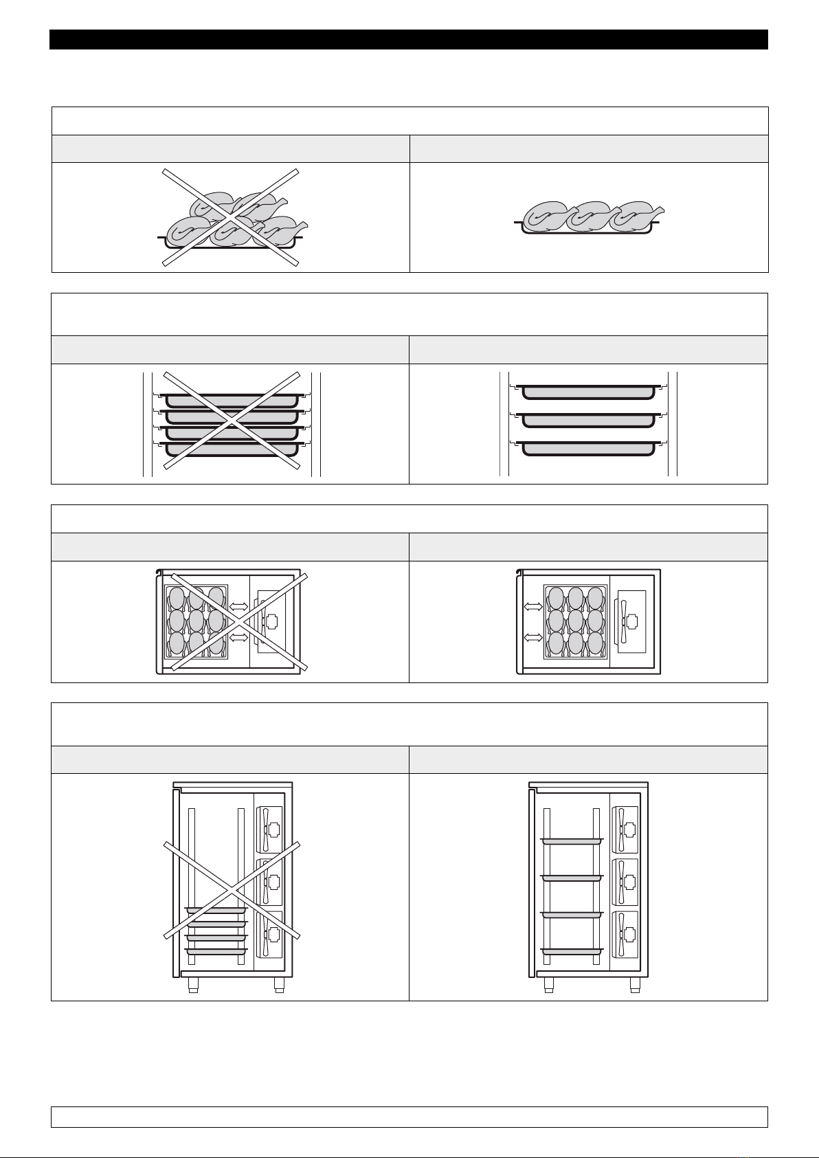
block of ice on the evaporator
misuse see chapter 1.
device to defrost press the manual defrost
defrost probe Pr3 damaged contact technical support
accumulation of water or ice in the
drip tray
drain clogged clean the pipette and the drain
blast chiller is not level check levelling
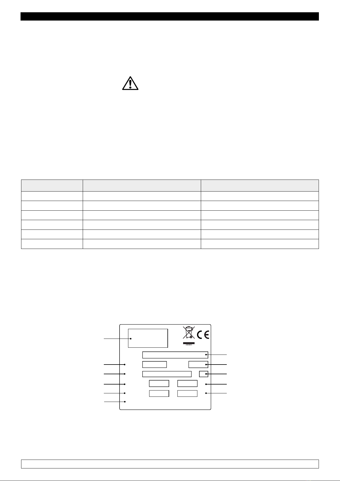
CHAPTER 7 INSTRUCTIONS FOR REQUESTING ASSISTANCE
For any technical problem and for intervention, assistance and spare-part requests it is necessary
to exclusively revert to one’s dealer, providing the code and the serial number indicated on the
specification label attached to the appliance.
CHAPTER 8 SAFETY AND ACCIDENT PREVENTION
The blast chiller has been built with suitable measures to ensure the safety and health of the user.
The following are the measures taken to protect against mechanical risks:
- stability: The blast chiller, even with the grilles removed, has been designed and built in such a way
that under the intended operating conditions, its stability is suitable for use without risk of overturning,
falling or unexpected movement
- surfaces, edges, corners: the accessible parts of the blast chiller are, within the limits allowed by
their functions, free of sharp angles and sharp edges, as well as rough surfaces likely to cause injury
- moving parts: were designed, constructed and arranged to avoid risks. Certain parts are equipped
with fixed guards so as to prevent risks of contact which may result in injury

6
ENGLISH
The following are the measures taken to protect against other risks:
- electricity: The blast chiller has been designed, built and equipped so as to prevent risks electrical,
in accordance with the specific legislation in force
- noise: The blast chiller has been designed and built in such a way that risks resulting from the
emission of airborne noise are reduced to the minimum level
8.1 safety devices adopted
It is absolutely forbidden (Fig. 2) :
- to tamper with or remove the evaporator housing casing that protects the user against the risk of
being cut by the evaporator fins and the movement of the motor fan inside.
- remove the labels applied at the inner edge of the engine compartment, showing the technical
specifications (1) and the instructions for grounding (2)
- remove the label applied on the evaporator guard and near the electrical wiring inside the engine
compartment, which warns the user to turn off the power supply before working on the unit (3)
- to remove the labels applied inside the engine compartment, indicating grounding (4)
- to remove the label applied on the power cord, indicating the type of power supply (5)
The manufacturer declines any responsibility for the safety of the blast chiller if this were to happen.
Fig.2
8.2 Indications for optimal operation
- do not obstruct the motor-compartment air intakes (place at minimum 50 cm from ceiling)
- place the foodstuffs on the appropriate shelves or containers. Do not place them directly on the
bottom, or leaning against the walls, doors or fixed guards
- close the doors carefully
- always keep the defrost water drain hole clear of obstructions
- limit, to the extent possible, the frequency and duration of door opening. Each opening causes a
change in the internal temperature
- perform periodically current maintenance (see chapter 3)

7
ENGLISH
CORRECT LOAD BLAST CHILLER
AVOID overloading the blast chiller beyond the set limits shown in the table
NO OK
Do not place the trays too close to each other so as to avoid uneven air circulation inside the blast
chiller
NO OK
Do not place the trays too far away from the evaporator
NO OK
Do not concentrate the trays in one area of the blast chiller in case the load is not complete; distribute
its height evenly
NO OK
In case of interruption or failure of the power supply circuit, prevent the opening of the doors in order to
maintain a uniform temperature inside the blast chiller.
If the problem persists longer than a few hours it is recommended to move the material to a suitable place.

8
ENGLISH
CHAPTER 9 CONTROLS
9.1 Description of the controls and of the keys ( Fig. 3)
The control panel is a digital thermoregulator for cold, and it is provided with 6 keys with specific
functions:
HARD
SOFT
Fig.3
The control keys of the blast chiller are:
START/STOP Key
Turns the blast chiller on or off, Pressing the key
for 3 seconds and allows you to start or stop a
cycle
DOWN Key
Reduces a value.
UP Key
Increases a value.
When control board is in “ON” mode, it activates
a manual defrosting cycle, pressing the key for 4
seconds. Only if the evaporator requires it.
HARD / SOFT Key
For selecting a Hard or Soft cycle.
FREEZING Key
Turns on a freezing cycle.
CHILLING Key
Turns on a positive chilling cycle.
Nb. To silence the acoustic BUZZER, press and release any key.

9
ENGLISH
Display
Visualization is carried out through a display where you can see four digits , once on, they turn blue,
and twelve icons. For ease of reference, from now on the four digits will be designed as “display”,
and each icon will be identified singularly.
DIGIT
ICONS
FREEZING Icon
►Flashes while selecting a freezing cycle
►Remains on during the freezing cycle
CHILLING Icon
►Flashes while selecting a chilling cycle
►Remains on during the chilling cycle
HARD Icon
HARD CHILLING / FREEZING
►Flashes while selecting a Hard chilling or freezing
cycle
►Remains on during the Hard chilling or freezing
cycle
Icons
TEMPERATURE-BASED CHILLING / TEM-
PERATURE-BASED FREEZING ICON
►Remains on while selecting:
- A chilling cycle with core probe
- A temperature-based freezing cycle
►Flashes during the test attesting that the core probe
has been correctly inserted
Icons
TIME CHILLING / TIME FREEZING ICON
►Remains on:
- While selecting a time chilling cycle
- While selecting a time freezing cycle
STORAGE Icon
►Remains on during a storage cycle
►Flashes when displaying the room’s temperature
DEFROSTING Icon ►Remains on while defrosting is being carried out
PRECOOLING Icon
►Remains on while precooling is being carried out,
and the room’s temperature has reached the pre-set
parameters
►Flashes when precooling is being carried out, and
the room’s temperature has not reached the pre-set
parameters

10
ENGLISH
FAHRENHEIT °F Icon ►Remains on when displaying a temperature mea-
sured in Fahrenheit degrees
CELSIUS °C Icon ►Remains on when displaying a temperature mea-
sured in Celsius degrees
MINUTES min Icon ►Remains on when displaying a time lapse ex-
pressed in minutes (e.g. the duration of a chilling /
freezing cycle)
OFF Icon
►Remains on when the device is connected and
is OFF.
9.2 INSTRUCTION FOR USE
9.2.1 Start-up
Before starting up the blast chiller, please make sure that the power wiring and the connection have
been performed as per dispositions in chapter 15.
When the control board is fed, a two-seconds lamp test is carried out.
There are 3 statuses of functioning:
OFF status:
►the blast chiller is being fed and is off The display only shows the icon, coloured
in red.
ON/STAND-BY status:
►the blast chiller is being fed, is on and waiting
for a working cycle to be carried out.
The display shows the room’s temperature
RUN status:
►the blast chiller is being fed, is on, and a
working cycle is being carried out.
The display shows the following information:
►if a chilling or freezing cycle with core probe
is being carried out, the display shows the
temperature detected by the probe
►if a chilling cycle or a time-based freezing is being
carried out, the display shows the time remaining
before the end of the current cycle
►if a storage cycle is being carried out, the display
shows the room’s temperature

11
ENGLISH
9.2.2 Turn on/off
- Make sure the keyboard is not locked (chapter 11) and that no procedures are being carried out.
Press the START/STOP (ON/OFF) key for 3 seconds to turn on and off the blast chiller.
The icon turns on or off.
9.2.3 Operation
The blast chiller carries out chilling or freezing cycles, which can be Hard and Soft, time-based (set-
ting the duration of the cycle) and temperature-based (checking the core temperature of the product
via core probe).
Before each working cycle, a precooling may be carried out (Par. 9.2.12).
Before each cycle with a core probe, a test is carried out, to make sure the probe has been correctly
inserted; if it is not inserted, time-based cycles will start automatically continued in time.
Each chilling / freezing cycle is followed by a storage cycle.
CHILLING
TYPE
TEMPERATURE
RANGE
SUGGESTED
PRODUCTS
CHILLING
SOFT
►Core temperature of the product +90°C / +3°C
►The air temperature inside the room never goes
below zero.
Delicate, thin or small
products such as vegeta-
bles, rice and fried pro-
ducts.
CHILLING
HARD
►Core temperature of the product +90°C / +3°C
►The air temperature inside the room reaches -20°C.
Ideal for dense, fat, big in
size or packed products.
FREEZING
SOFT
►Core temperature of the product +90°C / -18°C
►The air temperature inside the room reaches 0°C
during the rst phase, and reaches even -40°C during
the second phase.
Ideal for any foodstuff
that, once freezed, is due
to be stored for many
weeks or months. Soft
freezing is suitable for
delicate and small pro-
ducts, needing a softer
freezing process
FREEZING
HARD
►Core temperature of the product +90°C / -18°C
►The air temperature inside the room reaches -40°C
Ideal for any foodstuff
that, once freezed, is due
to be stored for many
weeks or months. Hard
freezing is suitable for
products that are big in
size and are not affected
by a fast temperature
decrease.

12
ENGLISH
DESCRIPTION OF CYCLES
POSITIVE CHILLING WITH CORE PROBE
SOFT - Chapetr 9.2.4
►Room temp. setpoint.: 0°C
►Core probe temp. setpoint.: 3°C
+
SORING CYCLE
►Setpoint Temp. room: 2°C
HARD - Chapetr 9.2.5
a) 1st phase
►Room temp. setpoint.: -20°C
►Core probe temp. setpoint.: 15°C
a) 2nd phase
►Room temp. setpoint.: 0°C
►Core probe temp. setpoint.: 3°C
+
STORAGE CYCLE
►Room temp. setpoint.: 2°C
POSITIVE TIME-BASED CHILLING
SOFT - Chapetr 9.2.6
100% of time Soft chilling
►Room temp. setpoint.: 0°C
+
STORAGE CYCLE
►Room temp. setpoint.: 2°C
HARD - Chapetr 9.2.7
60% of time Hard chilling
►Room temp. setpoint.: -20°C
40% of time Soft chilling
►Room temp. setpoint.: 0°C
+
STORAGE CYCLE
►Room temp. setpoint.: 2°C
FREEZING WITH CORE PROBE
SOFT - Chapetr 9.2.9
a) 1st phase
►Room temp. setpoint.: 0°C
►Core probe temp. setpoint.: +3°C
a) 2nd phase
►Room temp. setpoint.: -40°C
►Core probe temp. setpoint.: -18°C
+
STORAGE CYCLE
►Room temp setpoint: -20°C
HARD - Chapetr 9.2.8
►Room temp setpoint: -40°C
►Core probe temp. setpoint: -18°C
+
STORAGE CYCLE
►Room temp. setpoint.: -20°C
TIME-BASED FREEZING
SOFT - Chapetr 9.2.11
60% of time Soft chilling
►Room temp. setpoint.: 0°C
40% of time Hard chilling
►Room temp. setpoint.: -40°C
+
STORAGE CYCLE
►Room temp. setpoint.: -20°C
HARD - Chapetr 9.2.10
100% of time Hard chilling
►Room temp. setpoint.: -40°C
+
STORAGE CYCLE
►Room temp. setpoint.: -20°C

13
ENGLISH
9.2.4 POSITIVE SOFT CHILLING with core probe and subsequent storage
The time-based chilling and storage cycle consists in two phases:
►1st phase: Soft chilling cycle (Room temp. setpoint 0°C; Core probe temp. setpoint 3°C)
►2nd phase: Storage (Room temp. setpoint 2°C)
- Make sure the blast chiller is in “
ON/STAND-BY
” mode, that the keyboard is not locked (chapter 11) and
that no procedures are being carried out.
► Press and release the key: the icon starts ashing
The display shows the room’s temperature setpoint.
► It is possible to use the keys to modify this value.
► Press and release the key within 20
seconds:
and icons remain on, and a one-
minute test is carried out, to make sure the core
probe has been correctly inserted:
►If the test has a positive outcome, the chilling
cycle with core probe does not stop.
►If the test has a negative outcome (e.g. core
probe not inserted), the acoustic buzzer warns
us 3 times (each 10 seconds) that the core probe
has not been inserted. In this case there is no
need to press any keys, after 30 seconds a time-
based cycle automatically begins.
During the chilling cycle a temperature, the display shows the temperature detected by the
core probe, and the icon is on.
► It is possible to display the room’s temperature in any moment, pressing and releasing the
key.
►To restore the standard display mode, press and release the same key or do not operate for
15 seconds.
►Once the chilling cycle has been carried out, the blast chiller automatically switches to a
storage cycle.
►During the storage, the display shows the temperature detected by the room probe and the
icon is on.
► To stop any cycle, press the key.
NB: If the required temperature is not reached within the scheduled time (positive chilling: 90 min,
freezing: 240 min), a recursive beep is issued as warning.
The blast chiller keeps chilling / freezing until reaching the scheduled temperature. Failure to reach
the temperature within the scheduled time may take place when introducing products which are
bigger in size or weight compared with the standard ones or products with higher temperature of the
maximum allowed.

14
ENGLISH
9.2.5 POSITIVE HARD CHILLING WITH CORE PROBE and subsequent storage
The chilling cycle with core probe and subsequent storage consists in three phases:
►1st phase: Hard chilling cycle (Room temp. setpoint -20°C; Core probe temp. setpoint 15°C)
►2nd phase: Soft chilling cycle (Room temp. setpoint 0°C; Core probe temp. setpoint 3°C)
►3nd phase: Storage (Room temp. setpoint 2°C)
After completing a phase, the blast chiller automatically switches to the next one.
- Make sure the blast chiller is in “ON/STAND-BY” mode, that the keyboard is not locked (chapter
11) and that no procedures are being carried out.
► Press and release the key the icon starts ashing.
► Press and release the key the HARD and icon ash
The display shows the working setpoint during the chilling.
► It is possible to use the keys to modify this value.
► Press and release the key within 20
seconds
the , HARD and icon remain
on, and a one-minute test is carried out, to
make sure the core probe has been correctly
inserted:
►If the test has a positive outcome, the chilling
cycle with core probe starts.
►If the test has a negative outcome (e.g. core
probe not inserted), the acoustic buzzer warns
us 3 times (each 10 seconds) that the core
probe has not been inserted. In this case there
is no need to press any keys, after 30 seconds
automatically begins a time-based cycle.
During the chilling cycle, the display shows the temperature detected by the core probe, and
the icon is on.
► It is possible to display the room’s temperature in any moment, pressing and releasing the
key.
► To restore the standard display mode, press and release the same key or do not operate for
15 seconds.
► Once the chilling cycle has been carried out, the blast chiller automatically switches to a
storage cycle.
► During the storage, the display shows the temperature detected by the room probe and the
icon is on.
► To stop the cycle, press the key.

15
ENGLISH
NB: If the required temperature is not reached within the scheduled time (positive chilling: 90 min,
freezing: 240 min), the control board emits a repeated loud bleep as a warning.
The blast chiller keeps chilling / freezing until reaching the scheduled temperature. Failure of reaching
the temperature within the scheduled time may take place when introducing products which are
bigger in size or weight compared with the standard ones or products with higher temperature of the
maximum allowed.
9.2.6 SOFT TIME-BASED CHILLING and subsequent storage
In order to select a time-based chilling cycle, you just need to make sure not to insert the core probe.
The Soft time-based and storage cycle consists in two phases:
►1st phase:Soft chilling cycle (Room temp. setpoint 0°C during the whole cycle)
►2nd phase: Storage phase (Room temp. setpoint 2°C)
- Make sure the core probe is not inserted.
- Make sure the blast chiller is in “ON/STAND-BY” mode, that the keyboard is not locked (chapter
11) and that no procedures are being carried out.
► Press and release the key the icon starts ashing
The display shows the working setpoint during chilling.
► It is possible to use the keys to modify this value and modify the values with the same keys
► Press and release the key within 20
seconds:
The icons remain on and the cycle
starts
► The control board carries out a one-minute test, to make sure the core probe has been cor-
rectly inserted, the icon ashes during the whole test, and turns off at the end of it.
► If the core probe has not been correctly inserted, the acoustic buzzer warns us 3 times (each
10 seconds).
► There is no need to press any keys, a time-based cycle will automatically begin.
During the chilling, the display shows the temperature detected by the room probe and the
and min icons remain on.
► It is possible to modify the duration of the cycle by pressing the keys.
► To display the room’s temperature, press and release the . To restore the standard
display mode, press and release the same key or do not operate for 15 seconds.
►Once the chilling has been completed, according to the scheduled duration, the blast chiller
automatically switches to storage.
-During storage, the display shows the temperature detected by the probe, and the icon is on
.
►To stop the cycle, press the key.

16
ENGLISH
9.2.7 HARD TIME-BASED CHILLING and subsequent storage
In order to select a time-based chilling cycle, you just need to make sure not to insert the core
probe.
The Soft time-based and storage cycle consists in three phases:
►1st phase: Hard chilling cycle (60% of the whole duration of the cycle; Room temp. setpoint -20°C)
►2nd phase: Soft chilling cycle (40% of the whole duration of the cycle; Room temp. setpoint -0°C)
►3nd phase: Storage cycle (Room temp. setpoint: 2°C)
After completing a phase, the blast chiller automatically switches to the next one.
- Make sure the core probe is not inserted
- Make sure the blast chiller is in “ON/STAND-BY” mode, that the keyboard is not locked (chapter
11) and that no procedures are being carried out.
► Press and release the key: the icon starts ashing
► Press and release the key the HARD icon starts ashing
The display shows the working setpoint during the chilling.
It is possible to use the keys to modify this value
► Press and release the key within 20
seconds:
The ,HARD and icon remain on
and the cycle starts
► The control board carries out a one-minute test, to make sure the core probe has been cor-
rectly inserted, the icon ashes during the whole test, and turns off at the end of it.
If the core probe has not been correctly inserted, the acoustic buzzer warns us 3 times (each
10 seconds). There is no need to press any keys, a time-based cycle will automatically begin.
► During the chilling, the display shows the time remaining before the end of the cycle.
► The ’icon turns off, while the and min icons remain on.
► It is possible to modify the duration of the cycle by pressing the keys.
► To display the room’s temperature, press and release the key.
► To restore the standard display mode, press and release the same key or do not operate
for 15 seconds.

17
ENGLISH
►Once the Hard chilling has been completed, according to the scheduled duration, the blast
chiller automatically switches to chilling SOFT.
►display shows the time remaining before the end of the chilling, the
, and min remain on
► Once the chilling has been completed, according to the scheduled duration, the blast chiller
automatically switches to storage.
► During storage, the display shows the temperature detected by the probe, and the icon
is on.
► To stop the cycle, press the key.
9.2.8 HARD FREEZING WITH CORE PROBE and subsequent storage
The freezing time-based and storage cycle consists in two phases:
►1st phase:Hard freezing cycle (Room temp. setpoint -40°C; Core probe temp. setpoint -18°C)
►2nd phase: Storage cycle (Room temp. setpoint -20°C)
- Make sure the blast chiller is in “ON” mode, that the keyboard is not locked (chapter 11) and that
no procedures are being carried out.
► Press and release the key
The , and HARD icons starts
ashing
The display shows the temperature setpoint during the chilling.
► It is possible to use the keys to modify this value
► Press and release the key within 20
seconds:
The , , HARD and icon
remain on.
A test is carried out, to make sure the core
probe has been correctly inserted:
►If the test has a positive outcome, the
storing cycle with core probe is activated.
►If the test has a negative outcome, a time-
based chilling cycle is activated.
►During freezing, the display shows the temperature detected by the probe, and the
icon is on.

18
ENGLISH
► To display the room’s temperature, press and release the key. To restore the standard
display mode, press and release the same key or do not operate for 15 seconds.
► Once the freezing has been completed, the blast chiller automatically switches to storage.
► During storage, the display shows the temperature detected by the probe, and the icon
is on.
► To stop the cycle, press the key.
NB: If the required temperature is not reached within the scheduled time (positive chilling: 90 min,
freezing: 240 min), the control board emits a repeated loud bleep as a warning.
The blast chiller keeps chilling / freezing until reaching the scheduled temperature.
Failure to reach the temperature within the scheduled time may take place when introducing
products which are bigger in size or weight compared with the standard ones of the maximum
allowed.
9.2.9 SOFT FREEZING WITH CORE PROBE and subsequent storage
The Sorf temperature-based freezing and storage cycle consists in three phases:
►1st phase: Soft freezing cycle (Room temp. setpoint 0°C; Core probe temp. setpoint +3°C)
►2nd phase: Hard Freezing cycle (Room temp. setpoint -40°C; Core probe temp. setpoint -18°C)
►3nd phase: Storage cycle (Room temp. setpoint -20°C)
After completing a phase, the blast chiller automatically switches to the next one.
- Make sure the blast chiller is in “ON” mode, that the keyboard is not locked (chapter 11) and that
no procedures are being carried out.
►
Press and release the key The , and HARD icon starts
ashing
►
Press and release the key the HARD icon turns off
The display shows the temperature setpoint during the freezing.
►
It is possible to use the keys to modify this value
► Once the values have been modied, press and
release the
key
The , and icons remain on
and a test is carried out to make sure the probe
has been correctly inserted.
►
If the test has a positive outcome, the
temperature-based freezing cycle is activated.
►
If the test has a negative outcome, a time-
based chilling cycle is activated.

19
ENGLISH
► During the Soft freezing phase, the display shows the temperature detected by the probe, and the
icon is on.
►
To display the room’s temperature, press and release the key. To restore the standard
display mode, press and release the same key or do not operate for 15 seconds.
►
Once the Soft freezing phase has been completed, the blast chiller automatically switches to
freezing.
►
During the freezing phase, the display shows the temperature detected by the probe, and the
icon is on.
Once the freezing phase has been completed, too, the blast chiller automatically switches to the storage
phase.
►During the storage phase, the display shows the temperature detected by the probe, and the
icon is on.
► To stop the cycle, press the
key
NB: If the required temperature is not reached within the scheduled time (positive chilling: 90 min,
freezing: 240 min), the control board emits a repeated loud bleep as a warning.
The blast chiller keeps chilling / freezing until reaching the scheduled temperature.
Failure to reach the temperature within the scheduled time may take place when introducing products
which are bigger in size or weight compared with the standard ones of the maximum allowed.
9.2.10 HARD TIME-BASED FREEZING and subsequent storage
In order to select a HARD time-based freezing cycle, you just need to make sure not to insert the
core probe
The time-based freezing and storage cycle consists in two phases:
►1st phase: Hard Freezing cycle (Room temp. setpoint -40°C during the whole cycle)
►2nd phase: Storage cycle (Room temp. setpoint -20°C)
- Make sure the core probe is not inserted.
- Make sure the blast chiller is in “ON” mode, that the keyboard is not locked (chapter 11) and that
no procedures are being carried out.
►
Press and release the key:
The , and HARD icons starts
ashing
The display shows the working setpoint during the freezing.
►
It is possible to use the keys to modify this value.
This manual suits for next models
10
Table of contents
Other Everlasting Freezer manuals