Everlasting PASTRY BN 1 TNBV Installation instructions

ARMADIO REFRIGERATO
REFRIGERATED CABINET
ARMOIRE REFRIGEREE
KÜHLSCHRANK
PASTRY
ICE
PASTRY- ICE.03
Istruzioni�per�l'utilizzatore
User�Instruction
Instructions�pour�l'utilisateur
Benutzeranleitungen

2
PASTRY - ICE.03
Capitolo 1 NORME ED AVVERTENZE GENERALI
Section 1 STANDARDS AND GENERAL WARNINGS
Chapitre 1 NORMES ET AVERTISSEMENTS GENERAUX
Kap. 1 NORMEN UND ALLGEMEINE HINWEISE
1.1 DICHIARAZIONE DI CONFORMITA' - DECLARATION OF CONFORMITY
DECLARATION DE CONFORMITE - KONFORMITÄTSERKLÄRUNG
NOI - THE COMPANY - NOUS - DIE FIRMA
EVERLASTING S.R.L. - Fabbrica Frigoriferi Industriali
S.S. Cisa km. 161 - 46029 SUZZARA ( MN ) - ITALIA
.........................................
Suzzara ................................
Dichiariamo sotto la nostra esclusiva responsabilità che il prodotto ARMADIO REFRIGERATO
Declares, under its own sole responsibility, that the product designated REFRIGERATED CABINET
Déclarons sous notre responsabilité exclusive que le produit ARMOIRE REFRIGEREE
Erklärt unter der eigenen und ausschließlichen Verantwortung, daß das Produkt KÜHLSCHRANK
al quale questa dichiarazione si riferisce è conforme alle seguenti direttive europee:
to which the present declaration refers, complies with the following european directives:
auquel cette déclaration se rapporte, est conforme aux dispositions européennes suivantes:
auf das sich diese Erklärung bezieht, den folgende europäische Richtlinien entsprechen:
DICHIARAZIONE CE DI CONFORMITA'
CE DECLARATION OF CONFORMITY
DECLARATION CE DE CONFORMITE
KONFORMITÄTSERKLÄRUNG
Numero di serie
Serial number
Numéro de série
Seriennummer
"Macchine" 2006/42/CE
"Bassa tensione" 2006/95/CEE e successive modicazioni
"Compatibilità elettromagnetica" 2004/108/CEE e successive modicazioni
"Materiali ed oggetti destinati a venire in contatto con i prodotti alimentari" 89/109/CEE
"Direttiva 97/23/CE" (PED - Pressure Equipment Directive) apparecchi in classe 1
"Machines" 2006/42/CE
"Low voltage" 2006/95/EEC and subsequent modications
"Electromagnetic Compatibility" 2004/108/EEC and subsequent modications
"Materials and objects designed to come into contact with foodstuff" 89/109/EEC
"Directive 97/23/EC" (PED - Pressure Equipment Directive) appliances in class 1
"Machines" 2006/42/CE
"Basse Tensions" 2006/95/CEE et modications successives
"Compatibilité Electromagnétique" 2004/108/CEE et modications successives
"Matériels et objets destinés à entrer en contact avec des produits alimentaires" 89/109/CEE
"Directive 97/23/CE" (PED - Pressure Equipment Directive) appareils en class 1
"Maschinen" 2006/42/CE
"Niaderspannung" 2006/95/EG und nachfolgende Änderungen
"Elektromagnetische Verträglichkeit" 2004/108/EG und nachfolgende Änderungen
"Zum Umgang mit Nahrungsmitteln bestimmte Materialien und Gegenstände" 89/109/EG
"Richtlinie 97/23/EG" (PED - Pressure Equipment Directive) Geräte in Klasse 1
La persona autorizzata a costituire il fascicolo tecnico è Paolo Guidetti, legale rappresentante della ditta
EVERLASTING S.R.L. S.S. CISA KM 161 – 46029 SUZZARA (MN) – ITALIA, sede presso la quale è anche custodito.
The person authorized to constitute the technical le is Paolo Guidetti, legal representative of the Company
EVERLASTING S.R.L. S.S. CISA KM 161 – 46029 SUZZARA (MN) – ITALY, where the le is kept.
La personne autorisée à constituer le dossier technique est Paolo Guidetti, représentant légal de la société
EVERLASTING S.R.L. S.S. CISA KM 161 – 46029 SUZZARA (MN) – ITALIE, ou le dossier est conservé.
Die Person die berechtigt ist die technische Unterlagen zusammenzustellen ist Paolo Guidetti, gesetzlicher Vertreter der Firma
EVERLASTING S.R.L. S.S. CISA KM 161 – 46029 SUZZARA (MN) – ITALIEN, wo die Datei gehalten wird.

3
PASTRY - ICE.03
Cap. 8 Istruzioni per l'utilizzatore 4
8.1 Comandi................................................................. 4
8.2 Indicazioni relative all’uso ...................................... 4
Indice generale
Sect. 8 User instructions 6
8.1 Controls.................................................................. 6
8.2 Operation ............................................................... 6
Content
ITALIANO
ENGLISH
FRANÇAIS
Chap. 8 Instructions pour l'utilisateur 8
8.1 Commandes........................................................... 8
8.2 Indications relatives à l'utilisation ........................... 8
Index général
Kap. 8 Benutzeranleitungen 10
8.1 Bedienung ............................................................. 10
8.2 Gebrauchshinweise ............................................... 10
Inhaltsverzeichnis
DEUTSCH
Modelli disponibili 12
Tabella 1 caratteristiche tecniche 12
Schemi elettrici 13
Models 12
Table 1 technical features 12
Wiring diagrams 13
Modèles 12
Tableau 1 caractèristiques tèchniques 12
Schémas électriques 13
Modell 12
Tabelle 1 Teknische Mekmale 12
Elektronische Bedienung 13

4
PASTRY - ICE.03
Capitolo 8 ISTRUZIONI PER L’UTILIZZATORE
Le informazioni contenute in questo capitolo sono destinate all’utilizzatore oppure a personale non specializzato (vedi par. 1.3 Manuale
d’uso e manutenzione).
Una volta installata, secondo le istruzioni di cui al cap. 3 (vedi Manuale d’uso e manutenzione), la macchina è da considerare pronta
all’uso.
8.1 COMANDI
A seconda dei modelli la macchina verrà fornita di combinazioni diverse di comandi:
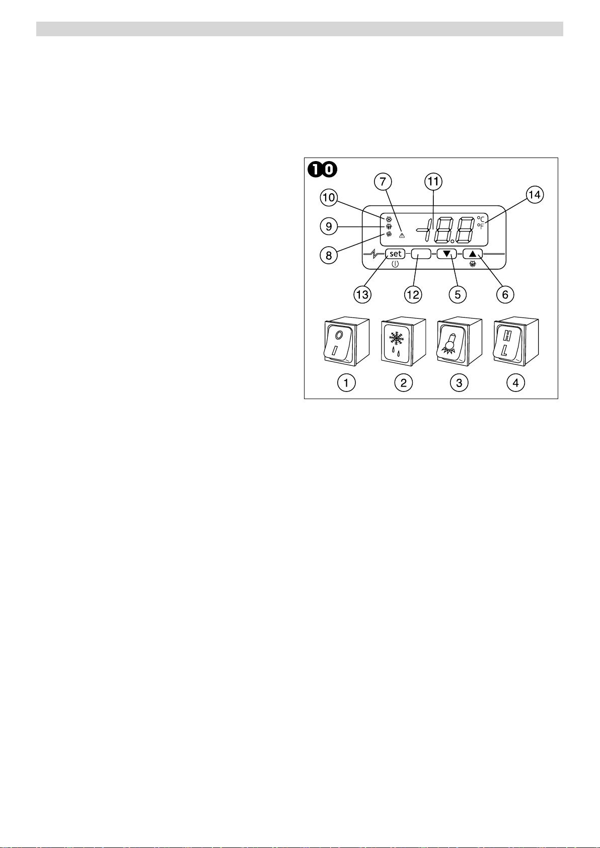
8.1.1 Descrizione dei comandi e pulsanti ( Fig. 10)
Il pannello di comando è un termoregolatore digitale per il freddo
ed è provvisto di 4 pulsanti con funzioni speciche:
I comandi di cui è dotata la macchina sono :
display (11) visore di temperatura e dello stato di funzionamento
della macchina
Tasto SET (13) accede al Set-point, conferma i parametri modi-
cati. Se premuto per oltre 4 secondi porta in standby l’armadio,
spegnendo il display e disattivando tutte le uscite digitali.
Tasto neutro (12) in questa applicazione il tasto non è abilitato.
Tasto UP (6) consente l’incremento dei valori, (temperatura più
alta) e, se premuto per 4 secondi all’attivazione manuale del ciclo
di sbrinamento. In combinazione con il tasto down permette di
visualizzare il menù parametri.
Tasto DOWN (5) consente il decremento dei parametri, (tempe-
ratura più bassa). Se premuto per 4 secondi consente di visua-
lizzare la temperatura della sonda evaporatore. Se premuto, in
combinazione con il tasto set il display visualizzerà LO e la tastiera
sarà bloccata, non sarà consentita nessuna modica. Premere
nuovamente entrambi i tasti contemporaneamente per sbloccare
la tastiera il display visualizzerà UN.
Se premuto, in combinazione con il tasto UP per 4 secondi si
accede al menù programmazione, protetto da password. Per
accedere ai parametri premere SET, inserire la password -19, premere il tasto SET per confermarla e premere contemporaneamen-
te i tasti UP e DOWN per 4 secondi il display indicherà d’essere nel menù visualizzando il primo parametro SP. Premendo Set si
visualizzerà il valore, con up o down si modicherà il valore. Esce automaticamente dal menù parametri non operando sulla tastiera
per 1 minuto o premendo nuovamente, contemporaneamente i tasti up e down per 4 secondi.
8.1.2 Allarmi e segnalazioni (g.10)
L’interruttore generale (1) è dotato di una spia luminosa che segnala la presenza di tensione.
Sul termoregolatore digitale compaiono le seguenti segnalazioni di funzioni in atto:
Led compressore (10) è acceso quando il compressore è in funzione, lampeggia quando è in attesa per protezione attivata com-
pressore.
Led sbrinamento (9) è acceso durante uno sbrinamento, lampeggia durante lo sgocciolamento.
Led ventilatore evaporatore (8) è acceso quando è in funzione il ventilatore, lampeggia quando è in attesa per tempo di ritardo atti-
vazione ventilatore.
Led unità di misura (14), indica se il termoregolatore legge la temperatura in gradi centigradi °C oppure in gradi Fahrenheit.
Led allarme (7) è acceso in caso di allarmi o anomalia sonde in corso.
In caso di allarme sul display possono comparire le seguenti label:
AL allarme di temperatura minima, la temperatura ha superato il minimo valore impostato.
AH allarme di temperatura massima, la temperatura ha superato il massimo valore impostato.
P1 errore sonda cella, la sonda del vano interno è guasta, il compressore rimarrà sempre in funzione.
P2 errore sonda evaporatore, la sonda evaporatore è guasta, lo sbrinamento e la ventilazione non verranno più regolati dai parametri
sonda ma saranno regolati da un programma di sicurezza. (sbrinamento per tempo massimo e ventilazione attiva con compressore
in funzione).
ITALIANO

5
PASTRY - ICE.03
8.2 INDICAZIONI RELATIVE ALL’USO
8.2.1 Avviamento
Prima di effettuare l’avviamento è necessario vericare che il collegamento elettrico e l’allacciamento siano stati realizzati come
previsto nei par. 3.3 e 3.4. Manuale d’uso e manutenzione.
E’ inoltre necessaria una pulizia preliminare secondo le modalità descritte nel par. 5.2.1 Manuale d’uso e manutenzione.
Sequenza d’avviamento (g.10).
Disporre l’interruttore generale (1) sulla posizione -1-.
Attendere che il pannello comandi cessi di lampeggiare.
Attivare gli eventuali comandi ausiliari.
8.2.2 Modi d’arresto
Disattivare gli eventuali comandi ausiliari.
Disporre l’interruttore generale (1) sulla posizione -0-.
8.2.3 Messa a punto e regolazione
La macchina è impostata dalla fabbrica per poter funzionare alle seguenti temperature:
- gamma TNBV PASTRY ( temperatura normale bassa ) - 2° C
- gamma BTV PASTRY ( bassa temperatura ) - 25° C
- gamma BTV ICE ( bassa temperatura ) - 25° C
- gamma BTST ICE ( bassa temperatura ) - 25° C
Se l’utilizzatore vuole operare in condizioni di temperatura diverse da quelle impostate deve agire come segue:
Comando elettronico (g.10)
Termoregolatore
Premere il tasto SET (13) e rilasciare, sul display compare il valore di Setpoint attuale.
Per incrementare il valore, agire sul tasto UP (6) e non operare su alcun tasto per 10 secondi oppure premere il tasto Set per con-
fermare il nuovo valore.
Per abbassare il valore, agire sul tasto DOWN (5) e non operare su alcun tasto per 10 secondi oppure premere il tasto SET per
confermare il nuovo valore.
8.2.4 Sbrinamento automatico e manuale
La macchina è impostata, dalla fabbrica, per poter effettuare lo sbrinamento automatico ad intervalli prestabiliti come segue :
- gamma TNBV ( temperatura normale bassa ) N.1 sbrinamento con durata 30’ ogni 8 ore di funzionamento
- gamma BTV ( bassa temperatura ) N.1 sbrinamento con durata 30’ ogni 6 ore di funzionamento
- gamma BTST ( statica ) sbrinamenti manuali durata 4 ore
ATTENZIONE: La gamma BTST Bassa temperatura statica è predisposta per degli sbrinamenti manuali, necessari quando lo
spessore del ghiaccio sulle pareti interne superi il centimetro. Dopo ogni sbrinamento manuale vericare la corretta pulizia
delle superci interne e procedere alla sua asciugatura, per evitare l’immediata formazione di ghiaccio una volta acceso.
Svuotare la bacinella di raccolta acqua di sbrinamento e riposizionarla correttamente nella sua sede
Per i modelli con Comando Elettronico,l’utilizzatore può effettuare uno sbrinamento manuale, a seconda delle proprie necessità,
agendo come segue ( Fig. 10 ) :
- premere, per oltre 3 secondi, il tasto UP/DEFROST ( 5 )
- durante il ciclo di sbrinamento il led DEF ( 8 ) rimane acceso
N.B: durante il ciclo di sbrinamento automatico o manuale sul pannello di comando rimane acceso l’indicatore
DEF ( 8 ) Al termine del ciclo di sbrinamento l’indicatore si spegne e la macchina riprende automaticamente il ciclo normale
di funzionamento.
ITALIANO
6
PASTRY - ICE.03
ENGLISH
Section 8 USER INSTRUCTIONS
The information in this section of the manual regards the user or other non-specialized personnel (see par. 1.3 in the “Instruction
and Maintenance Manual”). After the appliance has been installed in accordance with the instructions of section 3 of this manual, it
is ready for use.
8.1 CONTROLS
According to the models, the appliance is equipped of diffe-
rent types of controls:
8.1.1 Description of controls and pushbuttons (Fig.10)
The control panel is a digital refrigerating thermoregulator and
it is equipped with 4 keys with specic functions:
• display (11) visualizes the temperature and the working status
of the device.
• SET Key (13) allows access to Set-point, conrms the modi-
ed parameters. When pushed for over 4 seconds, the cabinet
turns into stand-by mode, the display is turned off and all the
digital outputs are deactivated.
• Neutral key (12) the key is not active on this application
• UP key (6) allows to increase the values (higher temperature)
and to manually activate the defrosting cycle when pushed for 4
seconds. In combination with the down key, it allows to display
the parameter menu.
• DOWN key (5) allows to decrease the parameters (lower tem-
perature). When pushed for 4 seconds, it allows to display the
evaporator probe temperature. If pushed in combination with the
set key, the writing LO will be displayed and the keyboard will
be locked without any possibility of modication. Push both keys
again to unlock the keyboard: the writing UN will be displayed.
When pushed for 4 seconds in combination with the down key,
the programming menu (protected by a password) will be ac-
cessed. To access the parameters, push the SET key, key in
the password -19, push the SET key to conrm it and push the Up and DOWN keys at the same time for 4 seconds. The menu will be
accessed, displaying the rst SP parameter. The value will be displayed by pushing the SET key, and it will be modied by pushing
the UP and DOWN keys. The menu will be automatically quit when not operating on the keyboard for 1 minute or by pushing again
the up and down key at the same time for 4 seconds.
8.1.2 Alarms and signals (drawing 10)
The general switch (1) is equipped with a warning light that indicates the presence of voltage.
The following signals appear on the thermoregulator to indicate the ongoing functions:
• Compressor led (10) is on when the compressor is working. It blinks when it is on hold to actively protect the compressor.
• Defrosting led (9) is on during a defrosting. It blinks during dripping.
•
Evaporator ventilator led (8) is on when the ventilator is working. It blinks when it is on hold for delay in the activation of the ventilator.
• Unit of measurement led (14),indicates whether the thermoregulator reads the temperature in Centigrade or in Fahrenheit de-
grees.
• Alarm led (7) is on in case of alarms or ongoing probe anomalies
In case of alarm, the following labels can be displayed:
• AL alarm for minimum temperature. The temperature has exceeded the minimum set value.
• AH alarm for maximum temperature. The temperature has exceeded the maximum set value.
• P1 chamber probe error. The internal chamber probe is broken. The compressor will continue working.
• P2 evaporator probe error. The evaporator probe is broken. The defrosting and the ventilation will not be controlled by probe param-
eters, but by a security program (defrosting at maximum time and ventilation active with compressor working).
8.2 USAGE INSTRUCTIONS
8.2.1 Start
Before starting the device it is necessary to control that the electrical and hydraulic connections have been effected as in par. 3.3 and
3.4 on the usage and maintenance manual.
Moreover, it is necessary to clean the device as per par. 5.2.1 on the usage and maintenance manual.
Start sequence (drawing 10).
• Place the general switch (1) on position -1-.
• Wait until the control panel stops blinking.
• Activate the auxiliary controls if necessary.
8.2.2 Stop modes
Deactivate any auxiliary control.
Place the general switch (1) on position -0-.

7
PASTRY - ICE.03 ENGLISH
8.2.3 Set-up and adjustment operations
The appliance is factory set for operation at the following temperature:
- TNBV range PASTRY (normal low temperature) - 2° C
- BTV range PASTRY (low temperature) -25° C
- BTV range ICE (low temperature) -25° C
- BTST range ICE (low temperature) -25° C
If you intend to use different temperatures, proceed as follows (Fig.10):
- press SET (12) and release, the display shows the “SET” label, press again to visualize the programmed temperature
- to increase the temperature, press the UP key (5) within 5 seconds
- to lower the temperature, press the DOWN key (4) within 5 seconds
The instrument automatically memorizes the programmed temperature last value.
8.2.4 Automatic and manual defrosting
The appliance is factory set for automatic defrosting at preset intervals as described below:
- TNBV range (normal low temperature) One 30' defrost cycle every 8 hours of operation
- BTV range (low temperature) One 30' defrost cycle every 6 hours of operation
If you wish to defrost Electronic Control models manually in accordance with effective requirements, proceed as follows (Fig.10):
- press the UP/DEFROST key (5) for more than 3 seconds
- during the defrost cycle the DEF led (8) remains illuminated.
N.B: during the automatic or manual defrost cycle the DEF led (8) on the control panel will be steadily illuminated. At the
end of the defrost cycle the led will switch off and the appliance automatically resumes its normal operating cycle.

8
PASTRY - ICE.03
FRANÇAIS
Chapitre 8 INSTRUCTIONS POUR L’UTILISATEUR
Les informations contenues dans ce chapitre sont destinées à l’utilisateur ou aux personnes non spécialisées (voir paragraphe 1.3
du livret d’instruction et entretien).
Une fois installé conformément aux instructions du chap. 3, l’appareil peut être considéré comme prêt à l’usage.
8.1 COMMANDES
L'appareil est fournì, selon les modèles, avec différents types de commandes:
8.1.1 Commande électronique
Description (Fig. 10)
Le panneau de contrôle est un thermorégulateur digital pour la réfrigération et il est pourvu de 4 touches à fonctions spéciques:
• écran (11) viseur de température et de l’état de fonctionnement
de la machine
• Touche SET (13) accède au Set-point, conrme les paramètres
modiés. Si appuyée pour plus de 4 secondes l’armoire passe à
la modalité stand-by, l’écran s’éteint et toutes les sorties digitales
se désactivent.
• Touche neutre (12) dans cette application la touche n’est pas
habilitée.
• Touche UP (6) permet l’augmentation des valeurs (température
plus haute) et, si appuyée pour 4 secondes au moment de
l’activation manuelle du cycle de dégivrage avec la touche
down permet de visualiser le menu paramètres.
• Touche DOWN (5) permet la diminution des paramètres
(température plus baisse). Si appuyée pour 4 secondes, elle
permet de visualiser la température de la sonde évaporateur. Si
appuyée en combinaison avec la touche set, l’écran visualisera
LO, le clavier sera verrouillé, et aucune modication sera
permise. Appuyer encore les deux touches en même temps pour
réactiver le clavier. L’écran visualisera UN. Si appuyée pour 4
secondes en combinaison avec la touche down, on accède au
menu programmation, qui est protégé par un mot de passe.
Pour accéder aux paramètres, appuyer sur SET, taper le mot
de passe -19, appuyer sur la touche SET pour le conrmer et
appuyer en même temps sur les touches UP et DOWN pour 4
secondes. L’écran indiquera d’être dans le menu en visualisant
le premier paramètre SP. En appuyant sur la touche Set la valeur
sera visualisée. Avec les touches up ou down la valeur sera modiée. On sort du menu paramètres en pas opérant sur le clavier pour
1 minute ou en appuyant en même temps sur les touches up et down pour 4 secondes.
8.1.2 Alarmes et signals (g.10)
L’interrupteur général (1) est pourvu d’une lumière clignotante qui signale la présence de tension. Sur le thermorégulateur digital
apparaitraient les signaux suivants de fonctions courantes:
• Led compresseur (10) est allumé quand le compresseur marche. Il clignote quand il est en attente pour protection activée du
compresseur.
• Led dégivrage (9) est allumé pendant un dégivrage. Il clignote pendant l’égouttage.
• Led ventilateur évaporateur (8) est allumé quand le ventilateur marche. Il clignote quand il est en attente pour temps de retard
activation ventilateur.
• Led pige (14), indique si le thermorégulateur lit la température en centigrades ou en degrés Fahrenheit.
• Led alarme (7) est allumé en cas d’alarmes ou d’anomalie des sondes en cours.
En cas d’alarme, les écritures suivantes peuvent apparaitre sur l’écran:
• AL alarme de température minimum: la température a dépassé la valeur minimum programmée.
• AH alarme de température maximum: la température a dépassé la valeur maximum programmée.
• P1 erreur sonde chambre: la sonde de la chambre est cassée, mais le compresseur marche quand-même.
• P2 erreur sonde évaporateur: la sonde évaporateur est cassée, le dégivrage et la ventilation ne seront plus commandés par les
paramètres de la sonde mais par un programme de sécurité (dégivrage par temps maximum et ventilation active avec compresseur
en marche).
8.2 INDICATIONS D’UTILISATION
8.2.1 Démarrage
Avant d’effectuer le démarrage il est nécessaire de vérier que le branchement électrique et les connexions ont été effectués comme
prévu aux par. 3.3 et 3.4 du manuel d’usage et entretien. En outre, un nettoyage préliminaire est nécessaire selon les modalités
décrites aux par. 5.2.1 du manuel d’usage et entretien.
Séquence de démarrage (g.11).
• Placer l’interrupteur général (1) sur la position -1-.
• Attendre que le panneau de contrôle s’arrête de clignoter
• Activer les éventuels commandes auxiliaires.

9
PASTRY - ICE.03 FRANÇAIS
8.2.2 Modalités d’arrêt
Désactiver les eventuels commandes auxiliaires.
Placer l’interrupteur général (1) sur la position -0-.
8.2.3 Mise au point et réglage
L’appareil est réglé, en usine, pour pouvoir fonctionner à la température suivante:
- gamme TNBV PASTRY ( température normale basse ) - 2° C
- gamme BTV PASTRY ( basse température ) - 25° C
- gamme BTV ICE ( basse température ) - 25° C
- gamme BTST ICE ( basse température ) - 25° C
Si l’utilisateur désire travailler dans des conditions de température différentes de celles réglées, il doit procéder comme
suit (Fig.10):
- Presser la touche SET (12) et relâcher, sur l’afcheur apparaît “SET”, presser de nouveau pour visualiser la température
programmée.
- Pour augmenter la température, agir sur la touche UP (5) dans les 5 secondes
- Pour abaisser la température, agir sur la touche DOWN (4) dans les 5 secondes
L’instrument mémorise automatiquement la dernière valeur de température programmée.
8.2.4 Dégivrage automatique et manuel
L’appareil est réglé, en usine, pour pouvoir effectuer le dégivrage automatique à des intervalles préxés, comme suit:
- gamme TNBV ( température normale basse) 1 dégivrage de durée 30’ toutes les 8 heures de fonctionnement
- gamme BTV ( basse température ) 1 dégivrage de durée 30’ toutes les 6 heures de fonctionnement
Pour les modèles à Commande Electronique, l’utilisateur peut effectuer un dégivrage manuel selon ses propres exigences, en
agissant comme suit (Fig. 10) :
- presser, pendant plus de 3 secondes, la touche UP/DEFROST (5)
- durant le cycle de dégivrage, la Led DEF (8) reste allumé
N.B: Durant le cycle de dégivrage automatique ou manuel, l'indicateur DEF (8) reste allumé sur le panneau de commande.
Au terme du cycle de dégivrage, l'indicateur s'éteint et l'appareil reprend automatiquement le cycle normal de
fonctionnement.

10
PASTRY - ICE.03
DEUTSCH
Kapitel 8 BENUTZERANLEITUNGEN
Die in diesem Kapitel aufgeführten Anleitungen sind für den Benutzer bzw. nicht ausgebildetes Personal bestimmt (siehe Par.1.3
Bedienungs- und Wartungsanleitung).
Nach der Installation gemäß den Anleitungen in Kap. 3 ist das Gerät betriebsbereit.
8.1 BEDIENUNG
Nach Modell Kann die Maschine mit verschiedenen Bedienungstypen geliefert werden:
8.1.1 Elektronische Bedienung
Beschreibung (Abb. 10)
Die Schalttafel ist ein digitaler Thermoregler für die Kühlung und
ist mit 4 Tasten mit spezischen Funktionen vorgesehen:
• Display (11) zeigt di Temperatur und das Funktionierungsstatus
des Geräts.
• Taste SET (13) erreicht das Set-point, bestätigt die geänderten
Faktorenwerten. Wenn sie für mehr als 4 Sekunden gedrückt
wird, bringt sie die Kühlschrank auf Stand-by, schaltet das
Display auf und sperrt alle digitale Ausgaben zu.
• Taste neutral (12) ist in dieser Applikation nicht aktiv.
• Taste UP (6) erlaubt die Zunahme der Werte (höhere
Temperatur), und wenn sie für 4 Sekunden im Moment der
manuellen Aktivierung des Abtauungszyklus zusammen mit
der Taste Down gedrückt wird, wird das Faktorenwertemenü
gezeigt.
• Taste DOWN (5) erlaubt die Abnahme der Faktorenwerten
(niedrigere Temperatur). Wenn sie für 4 Sekunden gedrückt
wird, wird die Temperatur der Verdampfersonde gezeigt. Wenn
sie zusammen mit der Taste set gedrückt wird, wird das Display
LO zeigen: die Tastatur wird gesperrt und keine Änderung wird
erlaubt. Die zwei Tasten gleichzeitig drücken, um die Tastatur
wieder zu aktivieren: das Display wird UN zeigen. Wenn sie mit
der Taste down für 4 Sekunden gedrückt wird, erreicht man das
Programmierungsmodus, das von einem Passwort geschützt ist.
Die Taste SET drücken, um die Faktorenwerten zu erreichen:
das Passwort -19 schreiben, die Taste SET drücken, um es zu
bestätigen und die Taste UP und DOWN für 4 Sekunden gleichzeitig drücken. Das Display wird zeigen, dass man im Menü ist, und
der erste Faktorenwert SP wird gezeigt. Indem man Set drückt, wird der wert gezeigt: mit up oder down der Wert wird geändert. Man
verlässt automatisch das Faktorenwertemenü indem man auf die Tastatur für 1 Minute nicht drückt, oder indem die Taste up und
down für 4 Sekunden gleichzeitig wieder drückt.
8.1.2 Alarme und Signale (Bild 10)
Der Hauptschalter ist mit einer Licht versehen, die die Anwesenheit von Spannung zeigt. Die folgende Signale für aktiven Funktionen
werden auf den digitalen Thermoregler gezeigt:
• Kompressorsled (10) ist an wenn der Kompressor funktioniert, blinkt wenn er wartet auf aktivierten Kompressorschutz.
• Abtauungsled (9) ist an während einer Abtauung, blinkt während das Tropfen.
• Verdampfersventilatorled (8) ist an wenn der Ventilator funktioniert, blinkt wenn er wartet wegen Verzögerung für die Aktivierung
des Ventilators.
• Maßeinheitsled (14) zeigt ob der Thermoregler die Temperatur mit Grad Celsius oder Fahrenheit liest.
• Alarmled (7) ist an bei Alarmen oder Unregelmäßigkeiten der Sonden.
Bei Alarmfall kann das Display die folgenden Label zeigen:
• AL Mindesttemperaturalarm, die Temperatur hat den eingestellten Mindestwert überschreiten.
• AH Maximaltemperaturalarm, die Temperatur hat den eingestellten Maximalwert überschreiten.
• P1 Fehler der Zellesonde, die Sonde des Innenraums ist kaputt, der Kompressor funktioniert auf jedem Fall.
• P2 Fehler der Verdampfersonde, die Sonde des Verdampfers ist kaputt, die Abtauung und die Ventilation werden nicht mehr von
den Sondeparametern kontrolliert, sondern von einem Sicherheitsprogramm (Abtauung bei Maximalzeit und aktive Ventilation mit
funktionierendem Verdampfer).
8.2 GEBRAUCHSANWEISUNGEN
8.2.1 Ingangsetzung
Vor der Ingangsetzung ist es nötig, zu kontrollieren, dass die elektrische und hydraulische Anschlüssen wie auf Par. 3.3 du 3.4 der
Gebrauchs- und Wartungsanleitung angefertigt wurden.
Es ist auch nötig, das Gerät wie auf Par. 5.2.1 der Gebrauchs- und Wartungsanleitung zu reinigen.
Ingangsetzungsreihenfolge (Bild 11).
• Der Hauptschalter (1) auf Position -1- stellen.

11
PASTRY - ICE.03 DEUTSCH
8.2.2 Stopparten
Die eventuellen Hilfskontrolle deaktivieren.
Der Hauptschalter (1) auf Position -0- stellen.
8.2.3 Einstellungen
Das Gerät wird werkseits für den Betrieb mit folgender Temperatur eingestellt:
- Bereich TNBV PASTRY (normale, niedrige Temperatur) - 2° C
- Bereich BTV PASTRY (niedrige Temperatur) - 25° C
- Bereich BTV ICE (niedrige Temperatur) - 25° C
- Bereich BTST ICE (niedrige Temperatur) - 25° C
Zur benutzerseitigen Änderung der eingegebenen Temperaturwerte ist folgendermaßen vorzugehen (Abb. 10):
• Paneel
- Auf Taste SET (12) drücken und wieder lassen; auf dem Display erscheint Led “SET”, noch einmal drücken zur Anzeige
...der angelegte Temperatur.
- Für Temperaturzunahme Taste UP (5) innerhalb 5 Sekunden drücken.
- Für Temperaturabnahme Taste DOWN (4) innerhalb 5 Sekunden drücken.
Das Gerät speichert automatisch der zuletzt eingegebenen Temperaturwert.
8.2.4 Automatisches und manuelles Abtauen
Das Gerät wird werkseits für automatischen Abtaubetrieb mit folgenden Zeitabständen eingestellt:
- Bereich TNBV (normale, niedrige Temperatur) 1 Abtauvorgang von 30 Minuten nach jeweils 8 Betriebsstunden.
- Bereich BTV (niedrige Temperatur) 1 Abtauvorgang von 30 Minuten nach jeweils 6 Betriebsstunden.
Für manuelles Abtauen bei Bedarf für Modellen mit elektronischer Bedienung ist benutzerseitig folgendermaßen
vorzugehen (Abb. 10):
- Taste UP/DEFROST (5) mindestens 3 Sekunden drücken.
- Beim Abtauzyklus bleibt die Led DEF (8) erleuchtet.
NB.: Beim automatischen oder manuellen Abtauzyklus bleibt auf dem Steuerpaneel die Anzeige DEF (8) erleuchtet. Nach
Ablauf des Abtauzyklus erlischt die Anzeige, und das Gerät nimmt automatisch den normalen Betriebszyklus wieder auf.
12
PASTRY - ICE.03
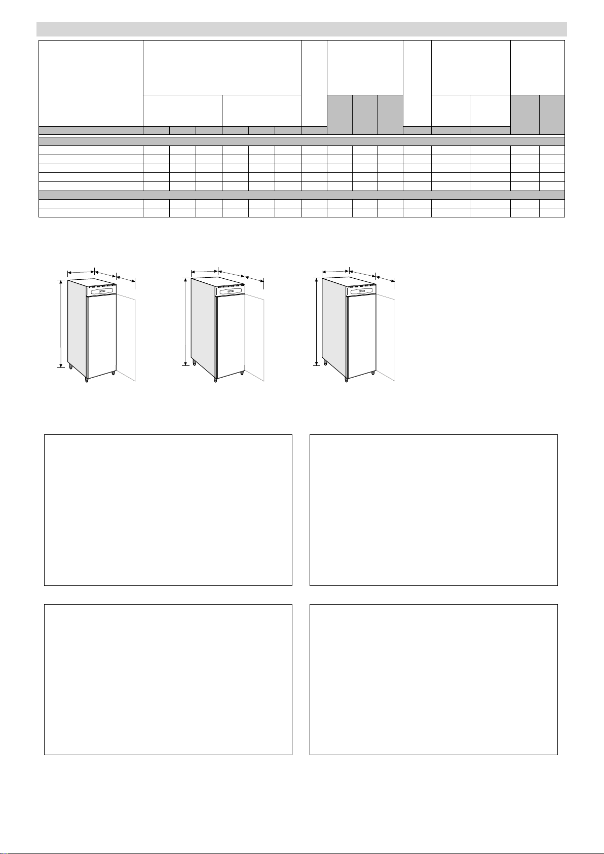
Modello - Model - Modèle - Modell
resa
output
fournie
Abgabeleis.
�
assorb.
absorb.
absorb.
aufgenomm.
�
BN 1 TNBV 850 2200 750 910 2200 820 150 162 195 217 573 812 380 R 404A 350
BN 1 BTV 850 2200 750 910 2200 820 160 172 205 227 573 833 780 R 404A 630
ICE 70 BTST 850 2200 750 910 2200 820 160 172 205 227 875 833 780 R 404A 450
BN 2 TNBV 850 2200 1050 910 2200 1120 190 212 235 157 875 1830 660 R 404A 450
BN 2 BTV 850 2200 1050 910 2200 1120 200 212 245 267 875 1630 1300 R 404A 600
ICE 100 BTST 850 2200 750 910 2200 820 150 162 195 217 573 1060 830 R 404A 500
ICE 100 BTV 850 2200 1050 910 2200 1120 200 212 245 267 875 1630 1300 R 404A 600
fluido refrigerante
refrigerant type
fluide frigorigène
Kältemittel
�
tipo
type
type
Typ
�
modello - model - modèle - Modell
ingombri del materiale imballato
Dimensions of packed material
encombrements du matériel emballé
Abmessungen verpackte Geräte
�
gabbia / cassa
crate/case
cage / caisse
Lattenverschlag/Holzkiste
�
cartone
cadboard
carton
Karton
�
cassa
case
caisse
Holzki
�
peso del materiale
imballato ( kg )
shipping weight ( kg )
poids du matériel
emballé ( kg )
Gewicht verpackte
Geräte ( kg )
�
potenza
power
puissance
Leistung
�
peso
unitario
unit
weight
poids
unitaire
Einheit
gewicht
�
TABELLA 1
TABLE 1
TABLEAU 1
TABELLE 1
�
cartone
c.board
carton
Karton
�
gabbia
crate
cage
Latten
�
volume
depos.
storage
volume
volume
dépôt
Lager
volumen
�
CP - Moto-compressore
HL - Selettore umidità
IG - Interruttore generale
IL - Interruttore luce
IP - Interruttore porta
K1 - Relé compressore
LI - Luce interna
MS - Morsettiera alimentazione
RB - Resistenza bacinella
RC - Resistenza scarico
RE - Reattore
RP - Resistenza anticondensa
RS - Resistenza sbrinamento
SA - Sonda termostato
SG - Valvola solenoide
SS - Sonda sbrinamento
LS - Lampada spia sbrinamento
S - Starter
Legenda componenti
UR - Unità remota
VC - Ventilatore condensatore
VE - Ventilatore evaporatore
Legenda colori
NE - Nero
GR - Grigio
AR - Arancio
RO - Rosso
MA - Marrone
BL - Blu
BI - Bianco
GV - Giallo-verde
RA - Rosa
VI - Viola
AZ - Azzurro chiaro
CP - Motor compressor
HL - Humidity selector
IG - Main switch
IL - Light switch
IP - Door microswitch
K1 - Compressor relay
LI - Interior light
MS - Power supply terminal board
RB - Condensate collecting tray heater
RC - Drain resistance
RE - Reactor
RP - Anti-condensate resistance
RS - Defrost resistance
SA - Thermostat sensor
SG - Solenoid Valve
SS - Defrost sensor
LS - Defrost warning light
S - Starter
List of components
UR - Remote unit
VC - Condenser fan
VE - Evaporator fan
Colour code
NE - Black
GR - Grey
AR - Orange
RO - Red
MA - Brown
BL - Blue
BI - White
GV - Yellow-Green
RA - Pink
VI - Violet
AZ - Light blue
CP - Motocompresseur
HL - Sélecteur humidité
IG - Interrupteur général
IL - Interrupteur lumière
IP - Interrupteur porte
K1 - Relais compresseur
LI - Lumière intérieure
MS - Bornier alimentation
RB - Résistance bac évaportaion
RC - Résistance évacuation
RE - Ballaste
RP - Résistance anti-eau de condensation
RS - Résitance dégivrage
SA - Sonde thermostat
SG - Soupape solénoÏde
SS - Sonde dégivrage
LS - Témoin dégivrage
S - Starter
Légende des composants
UR - Group à distance
VC - Ventilateur condenseur
VE - Ventilateur évaporateur
Légende des couleurs
NE - Noir
GR - Gris
AR - Orange
RO - Rouge
MA - Marron
BL - Bleu
BI - Blanc
GV - Jaune-vert
RA - Rose
VI - Violet
AZ - Bleu clair
Tabelle Teilebeschreibung
CP - Motorverdichter
HL - Feuchtigkeitswähler
IG - Hauptschalter
IL - Lichtschalter
IP - Türschalter
K1 - Verdichterrelais
LI - Innenlicht
MS - Klemmenleiste Versorgung
RB - Kondenswasserschale Heizung
RC - Ablaßwiderstand
RE - Reaktor
RP - Heizwiderstand
RS - Abtauwiderstand
SA - Temperatursensor
SG - Solenoidventil
SS - Abtausensor
LS - Abtauung Kontrollampe
S - Starter
UR - Entfernt installierte Einheit
VC - Verflüssigergebläse
VE - Verdampfergebläse
Tabelle Farben
NE - Schwarz
GR - Grau
AR - Orange
RO - Rot
MA - Braun
BL - Blau
BI - Weiß
GV - Gelb-Grün
RA - Rosarot
VI - Violett
AZ - Hellblau

13
PASTRY - ICE.03
HL
RS
RC
MA BL
VI
NE
RO
GR
BL
EVKB33
RS
RC
MA
BL
BL
RO
NE
RO
BL
MA
EVKB33
RB
MA

14
PASTRY - ICE.03
AZ
RA
BI
BL
BL
RO
NE

15
PASTRY - ICE.03
Tabella Parametri Armadi PASTRY-ICE con
Termoregolatore EVKB33 EVCO
Par. Descrizione Range VALORI IMPOSTATI
TNBV BTV BTST
SP Temperatura di set point r1;r2 -2 -20 -25
o1 Offset sonda cella -25;25 0 0 0
o2 Offset sonda evaporatore -25;25 0 0 0
P1 Punto decimale 0;1 0 0 0
P2 Unità di misura temperatura 0;1 0 0 0
P3 Funzione sonda evaporatore 0;1;2 1 1 0
r0 Differenziale setpoint 0,1;15 2 2 2
r1 Minimo setpoint di lavoro -99;r2 -2 -25 -25
r2 Massimo setpoint di lavoro r1;99 10 -12 -12
C0 Ritardo compressore all’accensione 0;199 0 0 0
C2 Ritardo compressore off-on 0;199 5 5 5
C3 Durata minima on compressore 0;199 0 0 0
d0 Intervallo di sbrinamento 0;99 8 6 0
d1 Tipo di sbrinamento 0;1 0 0 0
d2 Temperatura fine sbrinamento -99;99 8 8 8
d3 Durata massima sbrinamento 0;99 30 30 99
d4 Sbrinamento all’accensione 0;1 0 0 0
d5 Ritardo sbrinamento all’accensione 0;199 0 0 0
d6 Temperatura visualizzata in sbrinamento 0;1 1 1 1
d7 Durata sgocciolamento 0;15 2 2 2
dA
Durata minima on compressore per on sbrinamento a gas caldo
0;99 0 0 0
A1 Allarme temperatura minima 0;199 10 10 10
A4 Allarme di temperatura max 0;199 10 10 10
A6 Ritardo allarme massimo all’accensione 0;199 120 120 120
A7 Ritardo allarme temperatura 0;199 15 15 15
F0 Funzionamento Ventola evaporatore 0;1;2 1 1 0
F1 Temperatura evaporatore -99;99 4 40 4
F2 Ventilatori in sbrinamento 0;1 0 0 1
F3 Tempo ritardo ventilatori 0;15 2 2 2
i1 Contatto ingresso digitale NA-NC 0;1 0 0 0
i3 Durata massima attivazione digitale (solo i5=3-4) -1;120 15 15 15
i5 Effetto attivazione ingresso digitale 0;….;4 4 4 4
i7 Ritardo allarme on multifunzione -1;120 30 30 30
Rev.06/2010

EVERLASTING s.r.l.
46029 SUZZARA (MN) - ITALY - S.S. Cisa km.161
Tel.0376/521800 (4 linee r.a.) - Telefax 0376/521794
http://www.everlasting.it - E-mail:[email protected]
This manual suits for next models
9
Table of contents
Languages:
Other Everlasting Freezer manuals


